
Comparison of Camera based and Inertial Measurement Unit based
Motion Analysis
Seongho Jang
1
, Si-bog Park
1
, Sang-bok Moon
1
,
Jae Min Kim
2
and Shi-uk Lee
3
1
Department of Rehabilitation Medicine, Hanyang University, Seoul, Korea
2
Department of Neurosurgery, Hanyang University, Seoul, Korea
3
Department of Rehabilitation Medicine, Seoul National University Boramae Hospital, Seoul, Korea
Keywords: Motion Analysis, Inertial Measurement Unit, Gait.
Abstract: Camera-based 3D motion analyzers are widely used to analyze body movements and gait, but they are
expensive and require a large dedicated space. This study investigated whether inertial measurement unit
(IMU)-based systems can replace such systems by analyzing kinematic measurement parameters. IMUs
were attached to the abdomen and thigh and the shank and foot of both legs. The participant completed a 10
m-gait course 10 times and the hips, knees, and ankle joints were observed from the sagittal, frontal, and
transverse planes during each gait cycle. The experiments were conducted with both a camera-based system
and an IMU-based system. The measured gait analysis data were evaluated for validity and reliability using
RMSE. In this regard, the differences between the RMSE values of the two systems determined through
kinematic parameters ranged from a minimum of 1.39 to a maximum of 3.86. These results confirm that
IMU-based systems can reliably replace camera-based systems for clinical body motion analysis and gait
analysis.
1 INTRODUCTION
The level of improvement in gait and quantification
of body motion corroborate clinical decisions in the
treatment process and is used for functional
assessment in clinical gait analysis and
rehabilitation. Interest in gait evaluation and gait
improvement is increasing for non-patients as well
as young persons who have abnormal gait. Gait
analysis has evolved from a simple 2D video camera
analysis to optical motion capturing using several
infrared cameras and 3D motion analysis systems.
The 3D motion analyzers currently widely used for
gait analysis record body motion by reading location
coordinate values of body markers attached to in
body in real time with several infrared cameras in a
limited space.
However, both the purchase price and
maintenance of these motion analyzers are high.
Further, in order to take measurements from various
angles, several cameras and much space are
required. In addition, because such systems have to
be installed by professionals and require complex
setup and preparation for experiments and data
analysis, they are difficult to apply in clinical
settings.
Under different experimental conditions and
environments, the measurements obtained can also
differ based on the setting’s characteristics.
Consequently, issues concerning the validity and
reliability of the measurements obtained from these
machines also exist. With the aim of developing
systems that are without the disadvantages outlined
above, in recent times, research has been focused on
gait analysis using inertial measurement units
(IMU).
Recent advancements in sensor technology
enable simple and economic analyses to be
performed using IMUs. The inertial sensors usually
comprise a gyroscope, an accelerometer, and a
magnetometer, which enable economical
measurements of gravitational force and
acceleration. Changes in the Euler angle, yaw, pitch,
and angles of rolling axis can also be measured
using the gyroscope.
Numerous studies on gait analysis using inertial
sensors have focused on detection of gait phase, and
measurement of joint angles, segment angles, and
stride lengths. The results of these studies indicate
Jang, S., Park, S., Moon, S., Kim, J. and Lee, S.
Comparison of Camera based and Inertial Measurement Unit based Motion Analysis.
DOI: 10.5220/0006716601610167
In Proceedings of the 7th International Conference on Sensor Networks (SENSORNETS 2018), pages 161-167
ISBN: 978-989-758-284-4
Copyright
c
2020 by SCITEPRESS – Science and Technology Publications, Lda. All rights reserved
161
that wireless inertial sensor systems on the lower
body could analyze and evaluate the characteristics
of gait.
However, gain analysis data from the use of
inertial sensor systems are scarce. Furthermore,
because the technology is not considered fully
complete, inertial sensor systems are not widely
used for clinical gait analysis. Furthermore, their
accuracy is in doubt. In this study, the accuracy of
IMU-based sensor systems was investigated through
spatial-temporal and kinematic parameters on the
same subject and comparison with results from
camera-based 3D motion capture systems to
determine whether IMU-based systems can replace
camera-based systems.
In this study, a gait analysis system that analyzes
and quantifies the kinematic data of a specific part of
body was developed. Further, measurements
obtained from wearable IMU sensors on the lower
limb were compared to those from a camera-based
optical motion capture (OMC) system and their
validity evaluated. In addition, tests were conducted
in multiple settings to confirm the reliability and
effectiveness of IMUs. To the best of our
knowledge, no studies have reported on the
reliability of IMUs. Thus, confirmation of IMU
effectiveness and its accuracy will provide important
reference data for further studies in related fields.
The developed system can be applied in clinical and
rehabilitation settings.
2 MATERIALS AND METHOD
2.1 Participant and Gait Measurement
The subject of this study was a healthy adult male
with no musculoskeletal disabilities (age: 40s,
height: 180 cm, weight: 90 kg). The experiment was
conducted in three different hospitals (National
Rehabilitation Center, Veterans Health Service
Medical Center and Yonsei University Hospital)
between March 2016 and May 2016.
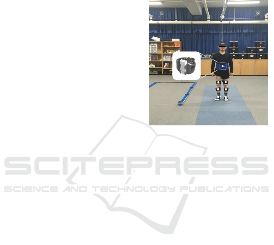
Each hospital had all the necessary equipment to
simultaneously conduct gait pattern analysis for both
the camera-based and IMU-based systems (Fig. 1).
In addition, the procedures in this test were
performed with the approval of Hanyang University
Guri Hospital (IRB File No. GURI 2015-03-001-
003).
The participant completed a 10 m-gait course 10
times in each experimental setting. During the gait
cycle, the kinematic parameters of hip, knee, and
ankle joint were inspected from the sagittal, frontal,
and transverse planes. In addition, the temporal-
spatial parameter was inspected. All experimental
trials were conducted in identical conditions.
Figure 1: Camera-based system and IMU-based system.
2.2 Experiment Equipment and
Procedure
For gait pattern analysis, the camera-based system
comprised VICON MX-T10 (Vicon Motion Systems
Ltd., Oxford, UK), which is the most widely used
system, and Motion Analysis (Raptor-E Digital Real
Time System; Motion Analysis, Santa Rosa, CA,
USA). The IMU (35 mm × 60 mm × 25 mm)-based
gait analysis system (Motion Track, R. Biotech Co.,
Ltd., Seoul, Korea) consisted of gyroscope,
accelerometer, and magnetometer sensors.
To evaluate the validity of the IMU, a reflective
marker-based 3D infrared camera system was
simultaneously used. The markers, used to analyze
the lower limb motion during gait were attached to
body using the plug-in-gait marker set method.
Wearable wireless IMUs were attached to the
abdomen, femur, tibia, and foot of both legs and
affixed with stretch bands. As shown in Fig. 2, the
IMU sensors were placed on a holder to increase
stability and accuracy (Fig. 2).
Each sensor’s signal was received and collected
using Bluetooth communication. The spatio-
temporal (gait cycle time, stance, swing phase,
velocity, distance, etc.) and kinematic (hip, knee,
ankle angle in three dimensions) data were
calculated using MATLAB
®
(ver. 2010a,
MathWorks Inc., USA). Before the actual
measurements, the participant underwent several
SENSORNETS 2018 - 7th International Conference on Sensor Networks
162
trials with the markers and IMUs attached in order to
familiarize himself with the gait conditions.
The validity of the gait analysis was analyzed
using the root mean square error (RMSE) of
parameters simultaneously obtained through the
camera-based system and the IMU-based system.
The reliability of the IMU was inspected using the
RMSE of kinematic parameters measured with the
IMU in three different experimental settings with a
certain time interval between each.
Figure 2: Hardware design of the IMU (the sensor was
placed in the holder).
2.3 Attitude and Heading Reference
Systems (AHRS) Module
In this study, inertial sensor-based AHRS was
designed and developed. When attached to the body
joints, the AHRS could measure the kinematic
motions of each joint objectively. In addition, the
AHRS measured the direction of the gravity and
magnetic field of the earth.
The AHRS module is composed of inertial
sensor, a microcontroller for receiving and
processing the signals, a Bluetooth module for
communication, and a battery charging circuit.
The inertial sensor used for the module in this
study was an integrated sensor (MPU9250,
Invensense, USA) composed of a gyroscope (range
± 2000 °/s), an accelerometer (range ± 16 g), and a
magnetometer (range ± 49 G). The signals were
programmed to be transmitted to the microcontroller
through SPI communication at 100 Hz in each
signal. The collected angular velocity, acceleration,
and magnetometer values were combined and the
gradient descent algorithm used to calculate the
Euler angle, yaw, pitch, and roll of the AHRS
module. The calculated values were transmitted to a
PC using a wireless Bluetooth module (PAN1321i,
Panasonic, Japan).
On the basis of the data from the magnetometer,
which provides data on the earth’s magnetic field
using the gradient descent algorithm, and data from
the accelerometer, which provides data on the
gravity and inertia, the gyroscope’s inaccurate
measurement of angular velocity was supplemented
and integrals were conducted to calculate and
reliably determine the Euler angle.
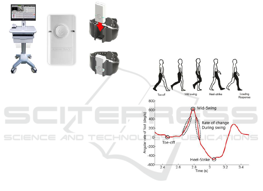
2.4 Gait Event Detection and Temporal
Parameters Calculation
The differential calculated from the foot’s Euler
angle determined the gait event, as shown in Fig. 3,
and the temporal parameters of gait were also
suggested. Fig. 3 explains the algorithm used to
determine the temporal parameter using gyroscope
on the foot. The figure shows the quantification of
the gyroscope features during the gait cycle of each
foot observed from the sagittal plane.
Figure 3: Graphical illustration of the algorithm used to
determine the gait event using rotation angle on the foot.
The inertial sensor data based on the verified
algorithm detected the heel strike (HS) and toe-off
(TO) points.
Peak rotation rate is the maximum achieved
rotation rate of the ankle during the swing phase.
The minimum value of TO is the minimum value
larger than the peak rotation value at mid-swing. In
addition, at HS, the peak of the negative rotation
value is observed at the first minimum after the
maximum rotation rate during the mid-swing period.
After the detection of HS and TO, the gait cycle
was formed to calculate gait temporal parameters.
Based on these time events, the temporal parameters
swing phase and stance phase can be calculated
using Eqs. (1) and (2), respectively.
Comparison of Camera based and Inertial Measurement Unit based Motion Analysis
163
Swing Phase, SW:
(1)
Stance Phase, :
(2)
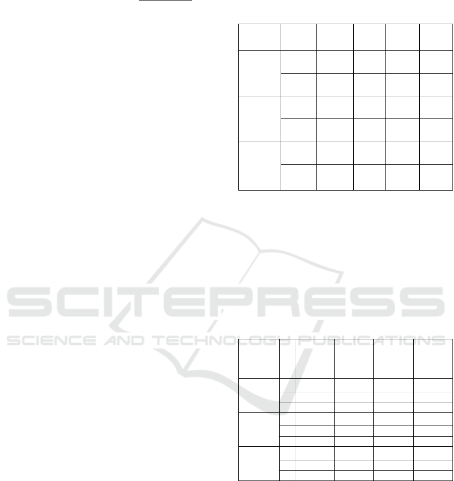
2.5 Spatial Parameters Calculation
In spatial parameters calculation, the distance
traveled by the subject is determined by the double
integration of momentary accelerations
measurements. The position or distance values
obtained by the integration is known to be suitable
only for a short term because of the drift error of the
accelerometer. In other words, calculation of
velocity and distance using the double integration of
acceleration measurements produced a relatively
large accumulated error. To avoid this accumulated
error, the values should be measured after every step
the pedestrian takes. If the velocity and distance
estimations are measured in each step, the
successive measurements of speed and distance are
not affected. Therefore, the accumulated error of the
AHRS was corrected. Fig. 4 shows a schematic
diagram of the two-phase cumulative error reduction
algorithm used to minimize the accumulated error of
the double integration, which was calculated using
the acceleration values and angular velocity from the
AHRS modules.
Velocity and distance were calculated by double
integrating the acceleration measurements. The
gravitation influences and accumulated error were
removed in order to calculate accurate values.
Figure 4: Spatial parameters calculation algorithm.
2.6 Calculation of Joint Angles
In order to measure the joint angles during
rehabilitation gait analysis, a total of seven AHRS
system modules were attached to the participant’s
joints. The modules were attached to the abdomen,
bilateral femurs, bilateral tibias, and the feet using a
stretch band, and the angle joints were calculated
using the Euler angles obtained from each joint. An
algorithm to calculate joint angles, which are
important biological measurement for rehabilitation,
was also developed in this study.
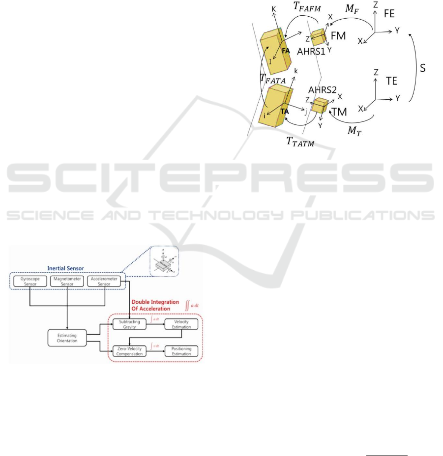
Fig. 5 shows a conceptual map of the algorithm
that calculates the joint angle in each segment. The
conceptual map uses the joint angle between the
femur and the tibia as an example. The example
shows the method used to calculate the angle
between the femur and tibia; the same algorithm can
be applied to other segmental joint angles.
Figure 5: Conceptual map of segmental joint angle
calculation method.
Fig. 5 represents tibia anatomical (TA) and femur
anatomical (FE), and each sensor axis was labeled as
tibia measurement (TM) and femur measurement
(FM). To convert the axis of each sensor into one
single axis, conversion matrix T
TATM,
which is a
matrix in which the sensor axis is converted to tibial
axis, and T
TAFM,
which is a matrix in which the
sensor axis is converted to femoral axis, were used.
The ultimate matrix that representing the joint angle
between the two sensors is expressed in Eq. (3).
(3)
In Eq. (3), S represents the alignment matrix
between two axis sensors of the earth (FE and TE)
while M
F
and M
T
represent the direction of the femur
and tibia relative to the earth axis. As shown in Eq.
(4), T
FATA
matrix terms were used to calculate the
joint angles flexion/extension, abduction/adduction,
and internal/external rotations:
)
(4)
SENSORNETS 2018 - 7th International Conference on Sensor Networks
164
3 RESULTS
In order to evaluate the performance of the gait
analysis system, the segmental joint angles on both
lower limbs were measured with seven AHRS
system modules. The attachment locations were the
abdomen, bilateral femurs and tibias, and the feet.
Based on the Euler angles of each joint provided by
the individual modules, the joint angles were
calculated with the joint angle calculation algorithm.
The Euler angles obtained from the AHRS in
segmental joints while the participant completed the
10 m-gait course were used to calculate joint angles
and 10 trials were conducted for measurement under
identical protocol.
Table 1 shows the inspection results for the
validity of the IMU-based system. The validity was
evaluated by comparing the temporal and spatial
parameters of the gait measured by the camera-based
and IMU-based systems in the three separate
hospitals.
The velocity measured with the IMUs was in the
range 1.16–1.20 m/s, whereas that measured with
the camera-based system was in the range 1.23–1.31
m/s. The stride lengths measured with the IMUs and
the camera-based system were in the ranges 1.15–
1.27 m and 1.19–1.32 m, respectively.
The stance phase (%) measured with the IMUs
was in the range 56–58%, whereas they were in the
range 61–63% for the camera-based system. The
swing phases (%) measured with the IMUs and the
camera-based system were in the ranges 42–44%
and 37–39%, respectively. Overall, the values
measured with the two systems did not show
significant differences.
Table 2 shows the inspection results for the
validity related to kinematic parameters of the IMU-
based system obtained by comparing the gait data
measured with camera-based and IMU-based
systems in three different hospitals. In order to
analyze the accuracy of the IMUs, the differences in
lower limb joint angles measured with the two
systems are shown. On the basis of the Euler angles
obtained from the AHRS modules on each body
segment, the segmental joint angles during gait cycle
were calculated. The values were processed in a 3D
space on the sagittal, frontal, and transverse planes.
Table 1: Temporal and spatial parameters of the camera-
based system and the IMU-based system obtained in the
three separate hospitals.
Velocity
(m/s)
Stride
length
(m)
Stance
phase
(%)
Swing
phase
(%)
National
Rehabilitatio
n Center
IMU
1.20
1.23
58
42
Vicon
1.31
1.19
63
37
Veterans
Medical
Center
IMU
1.18
1.27
58
42
Motion
analysis
1.25
1.32
61
39
Yonsei
University
Hospital
IMU
1.16
1.15
56
44
Vicon
1.23
1.23
61
39
The RMSE values of each of the sagittal, frontal,
and transverse planes are shown in Table 2. The
average RMSE value of the ankle joint angle on the
frontal plane was the lowest at 1.60. In addition, the
RMSE value of the ankle joint angle on the
transverse plane was the highest at 3.82. The results
verify the validity of the IMUs. The RMSE values
obtained at the hospitals are shown in Table 2.
Table 2: Kinematic parameters for the camera-based
system and the IMU-based system obtained at the three
hospitals.
National
Rehabilitat
ion Center
Veterans
Medical
Center
Yonsei
University
Hospital
Average
RMSE
Sagittal
H
1.80
1.46
2.14
1.80
K
2.87
2.37
2.91
2.72
A
1.63
2.26
1.43
1.77
Frontal
H
3.48
1.57
2.68
2.58
K
1.77
2.13
2.08
1.99
A
1.39
1.81
1.60
1.60
Transverse
H
3.86
3.72
4.25
3.94
K
2.99
3.01
2.95
2.95
A
2.88
3.35
5.23
3.82
H: RMSE of Hip Joint angle, K: RMSE of Knee Joint
angle A: RMSE of Ankle Joint angle
4 DISCUSSION
It has been reported that the mechanical accuracy of
IMUs could produce errors when measuring body
movements such as joint angle measurements.
During the measurement of acceleration and angular
velocity, the measurement plane of the IMU
Comparison of Camera based and Inertial Measurement Unit based Motion Analysis
165

modules on the body did not mechanically coincide
because of the curves on the body.
In this study, a camera-based system was
simultaneously used with the IMU-based system.
The differences between the RMSE values of the
two systems determined through kinematic
parameters with a tolerance close to 1%. Therefore,
the comparison results of two systems indicate that
IMU-based systems can replace camera-based
systems. The errors in joint angles during gait
analysis are within the tolerance range and the errors
could be reduced by replacing the gyroscope,
accelerometer, and magnetometer sensors with an
integrated sensor.
Further, the RMSE values of the kinematic
parameters measured with the IMU-based systems in
the three different experimental settings with a
tolerance close to 1%. Therefore, it can be inferred
that IMU-based systems are reliable for gait
analysis. Compared to the 2% error rate reported by
previous studies that used relatively more expensive
sensors, this study showed similar performance with
those studies that used high-cost sensors.
The limitations of this study include the fact that the
study was conducted on one participant and the
measurement session was extended over a long
period. Although the healthy participant tried to
maintain his health and physical activities for three
months during the experimental trials, the
measurements in different hospitals were taken over
an extended period.
Further studies on IMU-based gait analysis will
attract increased attention and demand. Therefore, a
system that provides feedback for gait correction and
evaluation will be developed in future work..
5 CONCLUSIONS
Gait analysis is currently conducted very rarely
owing to high equipment cost, complex procedure,
and space restriction. Therefore, an IMU-based
system was inspected to verify its validity and its
potential to replace camera-based systems. The
results indicate that IMU-based systems can be
effectively used in clinical settings and could be
applied to other fields that require gait analysis.
Furthermore, it is expected to be widely distributed
in related fields. Because IMU-based systems
provide accurate gait data in real time, they could
contribute to faster diagnosis and evaluation by
physicians.
This study verified the validity and the reliability of
IMU-based systems. The results indicate that IMU-
based systems can be widely used for rehabilitation
and gait analysis in clinical settings. It will be
necessary to develop interaction-coaching systems to
improve the accessibility of such systems. In
addition, a new type of gait analysis system that
portrays gait data as graphs, 3D avatars, and
webcams should be developed. The development of
IMU-based systems is expected to improve the
quality of patients’ lives as the cost for gait analysis
will consequently decrease.
ACKNOWLEDGEMENTS
This work was supported by Institute for
Information & communications Technology
Promotion(IITP) grant funded by the Korea
government(MSIP) (2017-0-01800).
REFERENCES
Simon, S. R., 2004. “Quantification of human motion:
Gait analysis - benefits and limitations to its
application to clinical problems,” Journal of
Biomechanics, Vol. 37, No. 12, pp. 1869-1880,
Sutherland, D. H., 2002."The evolution of clinical gait
analysis: Part II kinematics," Gait & Posture, Vol. 16,
No. 2, pp. 159-179,
Sutherland, D. H., 2005. "The evolution of clinical gait
analysis part III – kinetics and energy assessment,"
Gait & Posture, Vol. 21, No. 4, pp. 447-461,
Ugbolue, U. C. et al., 2013."The evaluation of an
inexpensive, 2D, video based gait assessment system
for clinical use," Gait & Posture, Vol. 38, No. 3, pp.
483-489,
Costigan, P. A. et al., 2002."Knee and hip kinetics during
normal stair climbing," Gait & Posture, Vol. 16, No.
1, pp. 31-37,
Favre, J. et al., 2008."Ambulatory measurement of 3D
knee joint angle," Journal of Biomechanics, Vol. 41,
No. 5, pp. 1029-1035,
Watanabe, T. et al., 2011."A preliminary test of
measurement of joint angles and stride length with
wireless inertial sensors for wearable gait evaluation
system," Computational Intelligence and
Neuroscience, Vol. 2011, Article No. 6,
Zheng, H. et al., 2005."Position-sensing technologies for
movement analysis in stroke rehabilitation," Medical
and Biological Engineering and Computing, Vol. 43,
No. 4, pp. 413-420,
Cloete, T., and Scheffer, C., 2008 "Benchmarking of a
full-body inertial motion capture system for clinical
gait analysis," in 2008 30th Annual International
Conference of the IEEE Engineering in Medicine and
Biology Society, pp. 4579-4582, IEEE,.
SENSORNETS 2018 - 7th International Conference on Sensor Networks
166

Boudarham, J. et al., 2013. "Variations in kinematics
during clinical gait analysis in stroke patients," PloS
one, Vol. 8, No. 6, pp. e66421,
Karasawa, Y. et al., 2013. "A trial of making reference
gait data for simple gait evaluation system with
wireless inertial sensors", in 2013 35th Annual
International Conference of the IEEE Engineering in
Medicine and Biology Society, pp. 3427-3430, IEEE,
Van Acht, V. et al., 2007. "Miniature wireless inertial
sensor for measuring human motions," in 2007 29th
Annual International Conference of the IEEE
Engineering in Medicine and Biology Society, pp.
6278-6281, IEEE,
Luinge, H. J., and Veltink, P. H., 2005. "Measuring
orientation of human body segments using miniature
gyroscopes and accelerometers," Medical and
Biological Engineering and Computing, Vol. 43, No.
2, pp. 273-282,
Zhu, R., and Zhou, Z., 2004. "A real-time articulated
human motion tracking using tri-axis inertial/magnetic
sensors package," IEEE Transactions on Neural
Systems and Rehabilitation Engineering, Vol. 12, No.
2, pp. 295-302,
Kim, M.-S. et al., 2014. "Development of a high-precision
calibration method for inertial measurement unit,"
International Journal of Precision Engineering and
Manufacturing, Vol. 15, No. 3, pp. 567-575,
Comparison of Camera based and Inertial Measurement Unit based Motion Analysis
167
