
Optimized Realization of Software Components with
Flexible OpenCL Functionality
Gabriel Campeanu, Jan Carlson and S
´
everine Sentilles
M
¨
alardalen Real-Time Research Center, M
¨
alardalen University, V
¨
aster
˚
as, Sweden
Keywords:
Software Component, Flexible Component, GPU, Embedded System, CBD, Component-based Development,
Component Model, OpenCL.
Abstract:
Today, the newly available embedded boards with GPUs provide a solution to satisfy the ever-increasing re-
quirements of modern embedded systems. Component-based development is a well-known paradigm used to
develop embedded systems. However, this paradigm lacks GPU support to address the specifics of these new
boards. This leads to components that typically have reduced reusability, poor maintainability and portability.
One way to tackle the existing shortcomings is through flexible components, i.e., platform-agnostic compo-
nents that, at design time, offer the possibility to be executed either on CPU or GPU. The current realization
of flexible components, i.e., as regular components with functionality tailored for the selected hardware, in-
troduces additional overheads such as component communication overhead. In order to tackle the introduced
overheads, our solution groups connected flexible components under a flexible group that conceptually behaves
as a component. We introduce an algorithm to identify the existing groups in a given component-based system
and the generation rules that automatically realizes groups as regular components. To evaluate the feasibility
of the new concept, the flexible group is implemented using a state-of-the-practice component model (i.e.,
Rubus) and examined through the vision system of an underwater robot.
1 INTRODUCTION
Modern embedded systems need to process huge
amount of data originated from the interaction with
the environment. For example, the autonomous
Google car
1
receives from the vehicle’s sensors (e.g.,
LIDAR, radar, camera) around of 750 MB of data per
second. This data needs to be processed with a suffi-
cient performance in order for the system to respond
in real-time to the environment changes such as mov-
ing pedestrians.
The traditional (CPU-based) embedded systems
have challenges in providing high performance when
processing huge amount of data. This is due to var-
ious issues such as limited computational resources
and the sequential execution model of the CPU.
One of the existing solution comes from the us-
age of the boards with Graphics Processing Units
(GPUs). Specifically developed with a parallel exe-
cution model, the GPU delivers an improved perfor-
mance compared to CPU, in the context of highly-
parallel applications such as molecular mechanics
1
https://waymo.com
simulations (Stone et al., 2007). OpenCL
2
is a pro-
gramming model supported by most of the existing
embedded boards with GPUs, that allows develop-
ment of functionality for both CPU and GPU.
In this work, we use component-based develop-
ment (CBD) to construct embedded systems. This
methodology promotes the development of applica-
tions through the composition of existing software
blocks known as (software) components. The adop-
tion of CBD in industry was successfully accom-
plished through several component models such as
AUTOSAR
3
, Rubus (H
¨
anninen et al., 2008) and IEC
611-31 (John and Tiegelkamp, 2010).
However, when it comes to the component-based
development of embedded systems with GPUs, the
existing component models provide no GPU support.
Therefore, the component developer needs to encap-
sulate all the GPU-related information inside the com-
ponent, which leads to several problems such as re-
duced reusability and poor maintenance (Campeanu
et al., 2017). For example, by encapsulating the num-
ber of GPU threads used, the component is reusable
2
https://www.khronos.org/opencl/
3
https://www.autosar.org
Campeanu, G., Carlson, J. and Sentilles, S.
Optimized Realization of Software Components with Flexible OpenCL Functionality.
DOI: 10.5220/0006691500770088
In Proceedings of the 13th International Conference on Evaluation of Novel Approaches to Software Engineering (ENASE 2018), pages 77-88
ISBN: 978-989-758-300-1
Copyright
c
2019 by SCITEPRESS – Science and Technology Publications, Lda. All rights reserved
77

only on platforms that have resources to fulfill the
component requirements.
To address these problems, we introduced in
our previous work the so-called flexible components
equipped with OpenCL functionality (Campeanu
et al., 2017). This type of component has a “flexi-
ble” behavior at the design time, that is, the system
designer can choose where to execute the component,
either on CPU or GPU. When the design is completed,
the flexible component is automatically realized as
a regular component compliant with the underlying
component model and with its functionality tailored
for the selected hardware. However, when several
flexible components that are allocated on the same de-
vice (i.e., CPU or GPU) are connected, unnecessary
overhead appears due to the following points:
• Each flexible component is realized as a com-
ponent that encapsulates, besides functional-
ity, required OpenCL device-environment to ad-
dress the hardware. The individual device-
environments encapsulated by the components are
identical and have the same purpose, i.e., access-
ing the same allocated device.
• The way that the functionalities of flexible com-
ponents communicate, being encapsulated inside
regular components, needs to comply with the
component model regulations. Hence, instead of
being achieved directly between functionalities,
data is exchanged through the interfaces of the
corresponding connected components, i.e., at the
component-level.
We propose a solution to tackle the unnecessary
overheads by identifying groups of connected flexible
components with the same hardware allocation. Con-
ceptually behaving as a single component, a flexible
group is realized as a regular component. The advan-
tages of the flexible group are the following:
• The realized (group) component encapsulates a
single OpenCL device-environment to access the
allocated hardware. All the functionalities of
the grouped components are executed through the
same device-environment.
• The communication between the functionalities
of the grouped components is done inside of the
realized (group) component. Therefore, data is
passed directly between the functionalities, i.e, at
the functionality-level, avoiding the overhead of
component interface communication. Moreover,
this way of realizing the communication inside the
flexible group, does not break the (flexible) com-
ponents encapsulation.
The realization of flexible groups as regular com-
ponents is implemented using a state-of-the-practice
component model (i.e., Rubus) and evaluated using
the vision system of an underwater robot.
The reminder of the work is divided as follows.
Background is covered by Section 2. The the defini-
tion of the flexible group is described in Section 3, and
its realization in Section 4. The evaluation is covered
by Section 5, followed by related work (Section 6)
and conclusions (Section 7).
2 BACKGROUND
The section is divided in three parts describing the
context of: i) component-based development in em-
bedded systems, ii) GPUs and OpenCL environment,
and iii) flexible components.
2.1 Component-based Development in
Embedded Systems
Component-based development is a software engi-
neering paradigm that promotes the construction of
systems through the composition of existing software
units called software components. A key concept of
CBD is the encapsulation principle where all the in-
formation are encapsulated inside a component, hid-
den from anything outside it. The only way to access
a component information is through the component
interface. In this work, we deal with port-based in-
terface, where a port is a component access point and
the interface encloses all the component (input and
output) ports.
The rules to construct components are given by
a component model. There exist many component
models, both from academia, e.g., ProCom (Sen-
tilles et al., 2008), and industry, e.g., AUTOSAR
4
and Rubus (H
¨
anninen et al., 2008). The compo-
nent model also introduce the way that components
interact. Based on the domain that the compo-
nent models are utilized in, different communication
styles are used (Crnkovic et al., 2011). For example,
AUTOSAR uses the request-response and sender-
receiver interaction styles in the automotive industry.
The interaction style used in our work is the pipe-and-
filter style used by e.g., Rubus and IEC 611-31. In this
particular interaction style, the component are seen as
filters while the communication links are pipes. The
pipe-and-filter style is suitable for streaming of event-
type of real-time and embedded applications, due to
the straightforward mapping between the control ap-
plication flow and the required control specifications
of the domain.
4
https://www.autosar.org
ENASE 2018 - 13th International Conference on Evaluation of Novel Approaches to Software Engineering
78
As we realize our solution using Rubus, we pro-
vide more details about this particular component
model. A Rubus component, called software circuit,
is equipped with two types of ports, i.e., trigger and
data ports. A Rubus component has one input and
one output trigger ports, and one or many (input/out-
put) data ports. Through the trigger port, the control
is passed between component; the data ports commu-
nicate (send/receive) data.
A Rubus component follows the Read-Execute-
Write execution model. Initially in an idle state, a
component is activated when its input trigger port re-
ceives the control (i.e., is triggered). The component
starts by Reading the data from all its input data ports,
followed by the Execution of the functionality using
the input data. The results are Written in the output
data ports, after which, the output trigger port is ac-
tivated and passes the control to the connected com-
ponent(s). After passing the control, the component
re-enters the idle state.
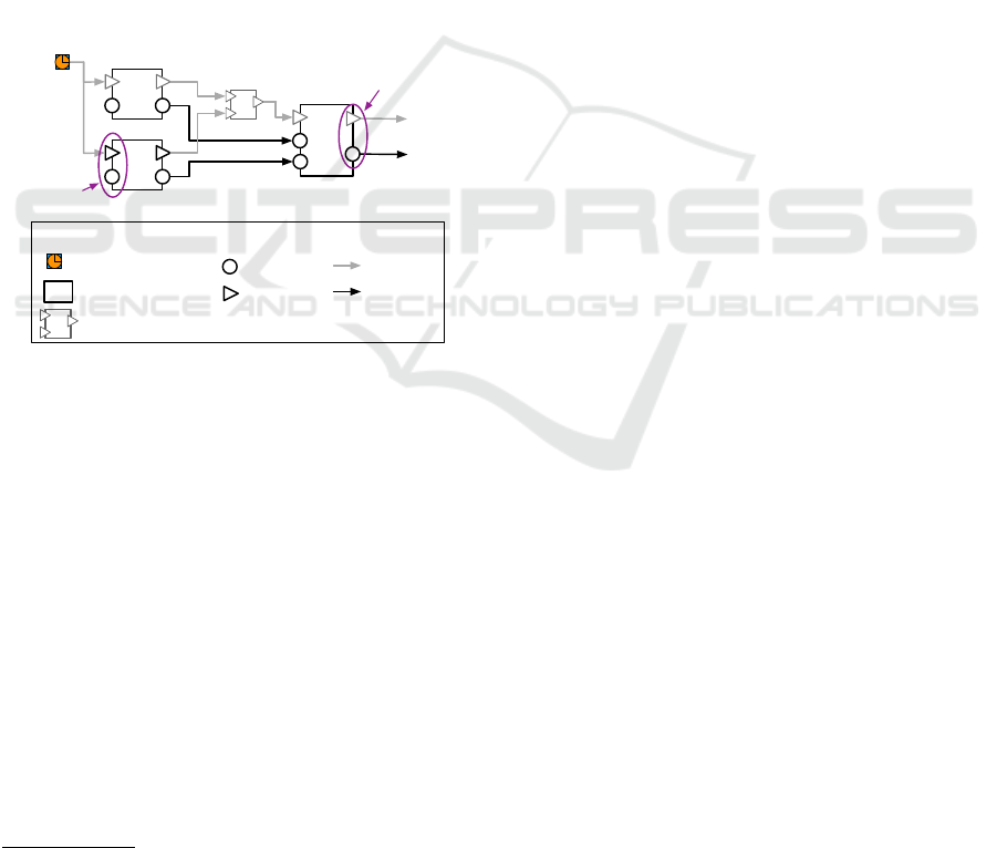
C1
C2
C3
Sync
Legend:
Rubus component
Data port
Trigger port
Synchronisation element of two triggering signals
Control flow
Data flow
Clock
Sync
Output ports
of C3
Input ports
of C2
…
Figure 1: Three Rubus connected components.
Figure 1 presents three connected Rubus compo-
nents, where C1 and C2 components are triggered by
the same clock element. After the execution of the
two components, the control is passed to C3 through
a synchronization element. The synchronization ele-
ment, similar to a logic gate, operates using different
logic functions, such as AND and OR.
2.2 GPUs and OpenCL
Nowadays, many programing models are used to ac-
cess the GPU hardware and develop functionality.
The two most used are CUDA
5
and OpenCL
6
. The
CUDA programming model is developed by NVIDIA
to specifically address their GPU platforms. OpenCL
is a programming model that addresses various num-
ber of processing unit such as m-CPUs, GPUs, FP-
5
http://docs.nvidia.com/cuda/cuda-c-programming-
guide/index.html
6
https://www.khronos.org/opencl/
GAs and DSPs. Being supported by most of the ex-
isting embedded platforms, OpenCL is used in this
work to construct the proposed solution.
The OpenCL model visualizes the hardware plat-
form as being composed of a host (i.e., CPU) and one
or several devices (e.g., CPU, GPU). The host, also
known as the system’s brain, is the one that triggers
all commands executed by the device(s). Several in-
terconnected steps are required to develop functional-
ity using the OpenCL model, as follows. 1) A plat-
form with the installed vendor’s driver, needs to be
defined; it contains a context and a command-queue.
The context is an environment that contains a num-
ber of selected devices; through the command-queue,
all the commands of the host are sent to the devices
enclosed by the context. 2) The functionality (i.e.,
one or several kernel functions) that will be executed
on the device(s) contained by the context, is enclosed
in a program object and compiled to construct a dy-
namic library. 3) Memory buffers need to be allo-
cated on the device, in order to e.g., hold the pro-
cessed data. 4) The kernel function(s), i.e., the func-
tionality of the application, need to be constructed.
5) Commands to execute the defined kernels are sub-
mitted to the command-queue. Before executing the
kernels, specific settings need to be defined, e.g., the
number of used device threads. After the function-
ality is executed, the results are copied back to the
host. In the end, the allocated resources (i.e., memory
buffers, program, context, command queue, kernels)
are released.
2.3 Flexible Components
A flexible component is a type of component that ex-
ists at the design time, where the system designer can
select the processing unit to execute it, i.e., either on
CPU or GPU. A flexible component C has a func-
tionality F
C
that is accessed through an interface I
C
.
There are two types of data ports enclosed in the in-
terface, i.e., regular and multi-element ports. Regu-
lar ports support regular data types, such as integer
and double. The multi-element ports support an in-
troduced multi-element type (i.e., m-elem type) used
to describe large data (e.g., 2D images). A multi-
element port is characterized by several information
to describe its data: i) width to describe the horizontal
size, ii) height to specify the vertical size, and iii) size
to denote the size of each data element. For example,
a color 2D image has a width of 256 pixels, a height
of 512 pixels, where each RGB pixel has a size of 3.
Furthermore, any (regular and m-elem) data port is
characterized by a type information and unique name.
The interface I
C
of a flexible component is com-
Optimized Realization of Software Components with Flexible OpenCL Functionality
79
posed of two subsets, i.e., I
C
in
and I
C
out
for input and
output ports, respectively. Furthermore, each subset
is divided according to the data types of the ports. For
example, I
C
in
contains I
C
reg in
for all the input ports of
regular types, I
C
multi in
for all input ports of m-elem
type and the input trigger port p
C
trigg in
.
After the system designer decides the hard-
ware allocation of the flexible components, an au-
tomatic realization converts them in regular compo-
nents (Campeanu et al., 2017). All the necessary code
corresponding to the component interface, construc-
tor, behavior function and destructor, is automatically
generated. Furthermore, the wiring between all the
initial connections of the flexible component’s ports,
are automatically accomplished to connect the ports
of the generated interface. The functionality of the
flexible component is included in the generated com-
ponent code, adjusted to be executed on the selected
hardware (i.e., CPU or GPU). Therefore, a suitable
OpenCL device-environment is automatically encap-
sulated inside the component, in order to access the
allocated hardware.
3 FLEXIBLE GROUPS
The usage of flexible components is an existing solu-
tion proposed by Campeanu et al. in (Campeanu et al.,
2017) to provide support for component-based de-
velopment of modern embedded systems with GPUs.
The existing solution realizes flexible components as
regular components, which introduces several over-
heads. In order to reduce these overheads, we pro-
pose to group connected flexible components with the
same hardware allocation, into what we call a flexible
group. The flexible group is realized as a component
that has the same allocation as the enclosed compo-
nents.
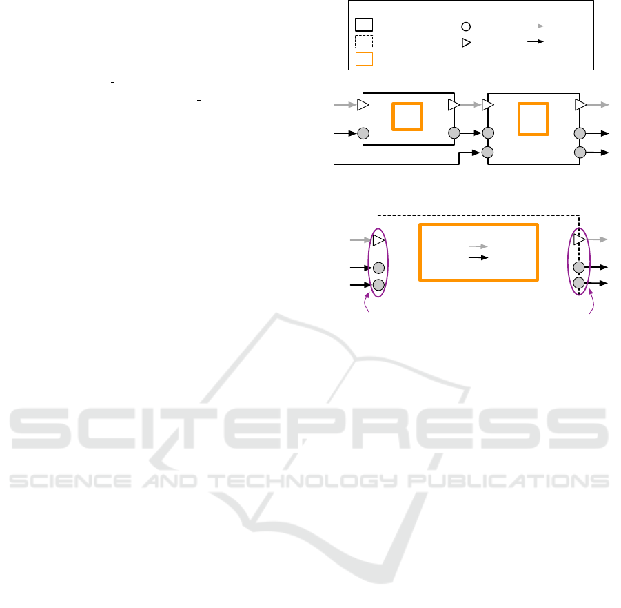
Our solution is described through a simple ex-
ample illustrated in Figure 2, where a flexible group
encloses two flexible components. Initially, Fig-
ure 2(a) presents two flexible components that com-
municate. After realization, each flexible compo-
nent (realized as a regular component) encapsulates
its own device-environment through which it executes
the functionality. The communication between the
components functionalities is done at the component-
level, through the components port-based interfaces.
Assuming that C
1
and C
2
are allocated on the same
hardware, using our approach, a flexible group G is
identified, containing C
1
and C
2
(i.e., Figure 2(b)).
In our vision, G contains one OpenCL device-
environment through which, the enclosed functional-
ities are executed. Furthermore, the communication
Legend:
Flexible component
Data port
Trigger port
Control flow
Data flow
Flexible group
Device environment
… …
OD2_C
2
ID2_C
2
F
C1
F
C2
IT_C
1
C
1
C
2
OT_C
1
ID1_C
1
OD1_C
1
IT_C
2
OT_C
2
ID1_C
2
OD1_C
2
(a) Two flexible components
OT_G
… …
group input interface
group output interface
ID2_C
2
F
C1
F
C2
G = {C
1
, C
2
}
ID1_C
1
OD2_C
2
OD1_C
2
IT_C
1
(b) A flexible group enclosing two components
Figure 2: The transition from flexible components to flexi-
ble group.
(i.e., data and control flow) between C
1
and C
2
is done
at the functionality level, i.e., directly between F
C1
and F
C2
, by providing the output of F
C1
as input of
F
C2
. Moreover, encapsulating F
C1
and F
C2
in G does
not break the encapsulation of C
1
and C
2
.
The group inherits the input and output ports
of the enclosed components, that communicate with
anything outside the group. Therefore, the group
input interface contains two input data ports, i.e.,
ID1 C
1
from C
1
and ID2 C
2
from C
2
, since these two
ports receive data from outside the group. The group
output interface has OD1 C
2
and OD2 C
2
data ports,
both inherited from C
2
. Furthermore, the group is
equipped with one input and one output trigger ports.
The remaining of the section presents the defini-
tion of the flexible group and the algorithm that iden-
tifies groups in a given component-based system.
3.1 Group Definition
We define a flexible group G as an ordered set of con-
nected flexible components that have the same hard-
ware allocation. The order of the components en-
closed in the set, determines their execution pattern:
G = {C
1
,C
2
,...}, where,
alloc(G) = alloc(C
k
), and
C
k−1
executes before C
k
ENASE 2018 - 13th International Conference on Evaluation of Novel Approaches to Software Engineering
80

The functionality of a flexible group is accessed
through the port-based group interface. The interface
I
G
is constructed from all the ports of the grouped
components that communicate with anything outside
the group, as follows. An input port of the group
is defined as an input port of any of enclosed com-
ponents, that receives information from a component
that is outside of the group. Similarly, an output port
of any enclosed component that sends data to exter-
nal component(s) is considered an output port of the
group.
I
G
= {p
1
, p
2
,...}, where p
m
∈ I
C
1
∪ I
C
2
∪ ...
The group interface is divided in two elements: i)
one for the input ports of the group, i.e., I
G
in
, and ii)
the other enclosing the output group ports, i.e., I
G
out
.
Furthermore, each (input and output) interface is di-
vided in subsets according to the enclosed data types
of the ports. For example, the group input interface
I
G
in
contains regular ports (I
G
reg in
), multi-element ports
(I
G
multi in
) and the input trigger port (p
G
trigg in
).
I
G
= I
G
in
∪ I
G
out
, where
I
G
in
= I
G
reg in
∪ I
G
multi in
∪ {p
G
trigg in
} and
I
G
out
= I
G
reg out
∪ I
G
multi out
∪ {p
G
trigg out
}
3.2 Group Identification
This section presents the algorithm that identifies the
flexible groups in a given component-based system.
We see the system as a directed graph, were each
component is a node and the trigger port connection
between two components is a directed vertex. In this
context, identifying the groups is similar to a depth-
first search algorithm.
The algorithm, described in Algorithm 1, starts
by initializing the main variables. For instance, Γ,
representing a set containing all identified groups in
the system, is initially an empty set. In Rubus, the
clock elements are the system elements that initiate
component triggering. Therefore, the algorithm starts
traversing the system from the clock elements, by
calling the main loop (i.e., the Top function) for each
triggered clock component. Initially, when starting to
traverse the system and there is no formed group, for
each encountered and not visited flexible component,
a new flexible group with the same hardware alloca-
tion is created. The component is added to the created
group and the group is added to Γ. The Top func-
tion is recursively executed for all of the component’s
triggering elements (e.g., regular component, flexible
component). In order to include all connected flexi-
ble components (with the same hardware allocation)
1 Γ ←
/
0
2 Visited ←
/
0
3 foreach clock C in the system do
4 Top(C, NULL)
5 end
6 Top(C, G):
7 if C /∈ Visited then
8 add(C, Visited)
9 if flexible(C) then
10 if G = NULL ∨ alloc(C) 6= alloc(G)
then
11 G ← createNewGroup()
12 alloc(G) ← alloc(C)
13 add(G, Γ)
14 end
15 add(C, G)
16 end
17 else
18 G ← NULL
19 end
20 foreach triggering edge C → C
0
do
21 Top(C
0
, G)
22 end
23 end
Algorithm 1: Identifying flexible groups.
in the same group, we use a reference to the current
group set. This reference is passed to the loop func-
tion as a parameter. Whenever a triggered flexible
component has a different allocation than the refer-
ence group, a new group is created and becomes the
current reference group.
4 GROUP REALIZATION
The flexible group is realized following the character-
istics of a regular component generation, i.e., through
an interface, constructor, behavior function and de-
structor, as follows. The generated interface con-
tains all the (input and output) data ports of the group.
The constructor generation initializes the resource re-
quirements of the group, e.g., allocates memory space
to hold the results from all enclosed components.
The group behavior executes the functionalities of
the grouped components. The destructor releases the
group allocated resources.
Furthermore, we re-wire the connections between
the group (input and output) interface and the in-
terfaces of (outside-the-group) components that were
initially connected to the group enclosed components.
Optimized Realization of Software Components with Flexible OpenCL Functionality
81

4.1 Code Generation
Using the existing way that Rubus defines the inter-
face of a regular component, we generate the group
interface in a similar manner, as presented in List-
ing 1. The SWC Group iArgs interface is defined
as a structure (lines 35-38) with two elements cor-
responding to the output and input interfaces. The
output interface OP SWC iArgs is constructed as a
structure (lines 28-32), where the elements are the
data ports of the group output interface I
G
out
. Simi-
larly, IP SWC iArgs is a structure that encloses the
data ports of the group input interface I
G
in
.
Besides input data ports, IP SWC iArgs interface
contains the so-called configuration ports. Each flex-
ible component is equipped with a configuration in-
terface. Through it, the system designer provides
appropriate settings regarding the number of device
threads used to execute the functionality. For exam-
ple, a flexible component allocated on GPU could re-
ceive, through the configuration interface, settings to
use 2048 GPU threads. In the flexible component re-
alization, the configuration interface is generated as
regular input data port in order to not introduce ad-
ditional Rubus framework elements. In our genera-
tion, we use the same rational, i.e, the flexible group
is equipped with a configuration interface generated
as an input data port, for each enclosed component
(line 22).
The settings received through the configuration in-
terface are inserted in the GPU settings structure. The
first four elements (lines 5-8) refers to the number
of device-threads used by the functionality, while the
rest of the elements (lines 9-11) are settings related to
the environment, such as the command queue mecha-
nism.
Listing 1: Interface code.
1 /
*
device-settings for each flexible component C
*
/
2 <counter = 1>
3 <foreach C in G>
4 typedef struct {
5 int blockDim_x;
6 int blockDim_y;
7 int gridDim_x;
8 int gridDim_y;
9 cl_context context;
10 cl_command_queue cmd_queue;
11 cl_device_id device_id;
12 }settings<counter+=1>;
13 <endforeach>
14
15 /
*
the group input ports
*
/
16 <counter = 1>
17 typedef struct {
18 <foreach p in I
G
in
>
19 <p.type>
*
<p.name>;
20 <endforeach>
21 <foreach C in G>
22 settings<counter> *cfg<counter>;
23 <counter += 1>
24 <endforeach>
25 }IP_SWC_iArgs;
26
27 /
*
the group output ports
*
/
28 typedef struct {
29 <foreach p in I
G
out
>
30 <p.type> <p.name>;
31 <endforeach>
32 }OP_SWC_iArgs;
33
34 /
*
the interface of the group
*
/
35 typedef struct {
36 IP_SWC_iArgs IP;
37 OP_SWC_iArgs *OP;
38 }SWC_Group_iArgs;
The constructor, illustrated in Listing 2, encloses
all the information regarding the group initialization,
as follows. The listing starts by allocating memory for
each flexible component from the group. That data re-
ceived by a component through the input ports is the
input data for the functionality, while the functional-
ity outcomes are sent through the output ports. There-
fore, corresponding to each output data port, we allo-
cate memory to hold the functionality results. Due to
the specifics of the OpenCL, a kernel function must
store a regular output value (e.g., integer value) in
a one-value memory buffer. Thus, we allocate one-
value memory buffers for regular output ports (line
4). For data of m-elem type, the memory buffer is al-
located with an appropriate size (line 8). Moreover,
in line 15, the multi-element ports that are considered
output ports of the group are linked to the correspond-
ing memory locations. This is done because these
ports will be wired to outside-of-the-group ports, and
the system communication will be accomplished by
using the values of the connected ports.
The core part of the constructor defines the group
functionality. A string variable encloses the func-
tionalities of the grouped components, i.e., the ker-
nel function name (line 21), the arguments (lines 23,
26, 29 and 32) that correspond to the input and out-
put component ports, and the component functional-
ity (line 37). The string variable is loaded into a pro-
gram object (line 43) and then compiled to create a
dynamic library (line 46). In the last part of the con-
structor, kernel objects are constructed for all flexible
components (line 51), alongside with the individual
settings regarding the number of used device-threads
(line 54 and 55). We mention that these settings are
provided by the system designer, using the configura-
tion interface port.
The reason to include the group functionality in-
side the constructor is to create the dynamic library
once (i.e., by creating and compiling the program ob-
ject), at the system initialization stage.
Listing 2: Constructor code.
1 /
*
create memory buffers for each flexible component
that is part of a flexible group
*
/
2 <foreach C in G>
3 <foreach p in I
C
reg out
>
4 void *result_<p.name> = apiCreateBuffer(settings->contex,
CL_MEM_WRITE_ONLY, sizeof(<p.type>),NULL,NULL);
5 <endforeach>
ENASE 2018 - 13th International Conference on Evaluation of Novel Approaches to Software Engineering
82

6
7 <foreach p in I
C
multi out
>
8 void *result_<p.name> = apiCreateBuffer(settings->contex,
CL_MEM_WRITE_ONLY, <p.width
*
p.height
*
p.size>,NULL,
NULL);
9 <endforeach>
10 <endforeach>
11
12 /
*
connect the output ports of the group with the
created memory buffers
*
/
13 <foreach C in G>
14 <foreach p in I
G
out
>
15 <p.name>->data = (unsigned char*) result_<p.name>;
16 <endforeach>
17
18 const char *source_string ="
19 <counter kernel = 1>
20 <foreach C in G>
21 __kernel void flexible_kernel<counter kernel>(
22 <foreach p in I
C
reg in
>
23 <p.type> <p.name>,
24 <endforeach>
25 <foreach p in I
C
reg out
>
26 __global <p.type> *result_<p.name>,
27 <endforeach>
28 <foreach p in I
C
multi in
>
29 __global <p.type> *<p.name>,
30 <endforeach>
31 <foreach p in I
C
multi out
>
32 __global unsigned char *result_<p.name>,
33 <endforeach>
34 ){
35
36 /* flexible component functionality */
37 <F
C
>
38 }";
39 <counter kernel += 1>
40 <endforeach>
41
42 /
*
Create a program from the kernel sources
*
/
43 cl_program program = clCreateProgramWithSource(settings->
context, 1, (const char **)&source_string, NULL, NULL);
44
45 /
*
Build the program
*
/
46 clBuildProgram(program,1,&(settings->device_id), NULL, NULL,
NULL);
47
48 <counter kernel=1>
49 <foreach C in G>
50 /
*
Create the kernel object
*
/
51 cl_kernel kernel<counter kernel> = clCreateKernel(program, "
flexible_kernel<counter+=1>", NULL);
52
53 /
*
individual settings - device threads usage
*
/
54 int total_thrd<counter
kernel>[2] = {(settings->gridDim_x),(
settings->gridDim_y)};
55 int group_thrd<counter kernel>[2] = {(settings->blockDim_x),
(settings->blockDim_y};
56 <counter kernel+= 1>
57 <endforeach>
The execution of the group functionality is en-
closed in the behavior function (Listing 3) which is
performed every time the group is activated. To ex-
ecute the functionality using the OpenCL model, the
host needs to send to the selected device (i.e., CPU
or GPU), the execution command of the desired ker-
nel function. However, before triggering the execu-
tion, the input data and locations for output results
need to be specified. Hence, the first part of the be-
havior function handles the parameters (i.e., provide
the values) of the group enclosed kernels. Basically,
the parameters of a kernel are the input data and out-
put data location of the corresponding flexible compo-
nent. For the input ports of the enclosed components
that are not considered the group ports, we provide
the values received from the connected ports. This
is done by directly providing the allocated memory
location corresponding to the connected ports (lines
11 and 25). In this way, the communication between
kernel functions of different connected components is
directly realized inside the group, at the functionality
level.
For (regular and multi-element) output ports, we
provide the data existing in the corresponding allo-
cated memory (lines 16 and 31). Based on the order
of the grouped set, the functionalities (i.e., the ker-
nel objects) of the enclosed components are triggered
to be executed on the selected hardware (line 39). In
the last part, we copy the computed one-value of the
allocated memory buffers, to the corresponding reg-
ular data output ports of the group (line 49). When
the wiring between existing system components and
groups will be done, the regular output ports of the
group will provide a regular data (e.g., integer value)
instead of a (one-value) memory buffer (i.e., pointer).
In this way, the Rubus rules that realizes communica-
tion between data ports are not interfered.
Listing 3: Behavior function.
1 /
*
Set the kernel arguments of each enclosed component
*
/
2 <counter kernel = 1>
3 <counter arg = 0>
4 <foreach C in G>
5 <for each p in I
C
reg in
>
6 /
*
for regular input ports of flexible components
that are considered input ports of the group
*
/
7 <if (p in I
G
reg in
)>
8 apiSetKernelArg(kernel<counter kernel>,<counter arg+=
1>, sizeof(<p.type>), (void*)&<p.name>);
9 /
*
for regular input ports of flexible components
that are not input ports of the group
*
/
10 <else>
11 apiSetKernelArg(kernel<counter kernel>,<counter arg+=
1>, sizeof(<p.type>), (void*)&result_<p.name>);
12 <endif>
13 <counter kernel+= 1>
14 <endforeach>
15 <for each p in I
C
reg out
>
16 apiSetKernelArg(kernel<counter kernel>,<counter arg>,
sizeof(<p.type>), (void*)&result_<p.name>);
17 <counter+= 1>
18 <endforeach>
19 <foreach p in I
C
multi in
>
20 /
*
multi-element input ports of flexible components
that are input ports of the group
*
/
21 <if (p in I
G
reg in
)>
22 apiSetKernelArg(kernel<counter kernel>,<counter arg>,
<p.width
*
p.height
*
p.size>, (void*)&<p.name>);
23 /
*
multi-element input ports of flexible components
that are not input ports of the group
*
/
24 <else>
25 apiSetKernelArg(kernel<counter kernel>,<counter arg>,
<p.width
*
p.height
*
p.size>, (void*)&result_
<p.name>);
26 <endif>
27
28 <counter+= 1>
29 <endforeach>
30 <for each p in I
C
multi out
>
31 apiSetKernelArg(kernel<counter kernel>,<counter arg>,
<p.width
*
p.height
*
p.size>, (void*)&result_
<p.name>);
32 <endforeach>
33 <counter kernel+=1>
34 <endforeach>
35
36 /
*
Execute the OpenCL kernels of the flexible
components
*
/
37 <counter=1>
Optimized Realization of Software Components with Flexible OpenCL Functionality
83

38 <foreach C in G>
39 clEnqueueNDRangeKernel(settings->cmd_queue, kernel<counter>,
2, NULL, total_thrd<counter>, group_thrd<counter>,
0, NULL, NULL);
40 <counter+=1>
41 <endforeach>
42
43 /
*
Wait for command queue and device to finish their
activities
*
/
44 clFlush(settings->cmd_queue);
45 clFinish(settings->cmd_queue);
46
47 /
*
copy the regular output(s) to the corresponding
regular output port(s) of the group
*
/
48 <foreach C in G>
49 <foreach p in I
G
reg out
>
50 apiEnqueueReadBuffer(settings->cmd_queue, result_<p.name>,
CL_TRUE, 0, sizeof(<p.type>), &<p.name>, 0, NULL,
NULL);
51 <endforeach>
52 <endforeach>
The destructor releases the resources allocated by
the constructor. Basically, the kernel objects (line 4),
the program object (line 7) and the allocated memory
buffers (line 10) are released.
Listing 4: Destructor code.
1 /
*
Clean up
*
/
2 <counter kernel = 1>
3 <foreach C in G>
4 clReleaseKernel(kernel<counter kernel>);
5 <counter kernel+=1>
6 <endforeach>
7 clReleaseProgram(program);
8 <foreach C in G>
9 <foreach p in I
C
out
>
10 apiReleaseBuffer(result_<p.Name>);
11 <endforeach>
12 <endforeach>
4.2 Connection Rewiring
The way that the Rubus framework generates the
wiring between components needs to be partially
changed by the fact that several grouped flexible com-
ponents are generated as a single component. Inside
the group, the rules that generate the wiring between
the enclosed components are ignored because the data
communication is accomplished at the functionality
level instead, i.e., inside the generated behavior func-
tion of the group (Listing 3, lines 11 and 25). The
connections between the group’s components and ev-
erything outside the group needs to be modified in the
following way. Instead of generating the wiring be-
tween the interfaces of the outside-the-group compo-
nents and the interfaces of the enclosed components,
we re-wire the connections between the interfaces of
the outside components and the group.
The trigger connection leading in to the group is
handled in the same way as the data connections, but
outgoing trigger connections should all be rewired to
originate from the single output trigger port in the
group interface.
Thus, when realizing a connection from port p
1
of
component C
1
to port p
2
of component C
2
(i.e., where
p
1
∈I
C
1
and p
2
∈I
C
2
), three cases must be considered:
• If ∃G : C
1
∈G ∧C
2
∈G, then no connection
should be generated.
• If ∃G : C
1
6∈G ∧C
2
∈G, then the connection
should be generated to the realization of p
2
belonging to the group G (since there is no
individual realization of component C
2
).
• If ∃G : C
1
∈G ∧C
2
6∈G, there are two sub cases:
– If p
1
and p
2
are data ports, then the connection
should be generated from the realization of p
1
belonging to the group G.
– If p
1
and p
2
are trigger ports, then the connec-
tion should be generated from the realization of
p
G
trigg out
(the trigger output port of the group G).
Following the Rubus approach, the re-wiring is
done at the system realization stage, before the sys-
tem is actual executed. Therefore, there is no system
execution overhead introduced by the re-wiring real-
ization.
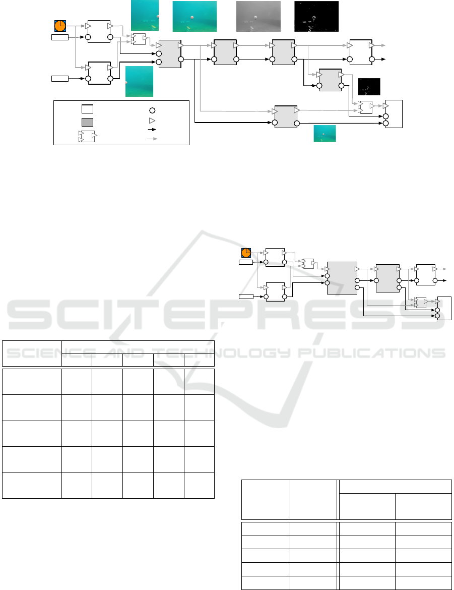
5 EVALUATION
To evaluate our solution, we use as a case study
the vision system of an underwater robot (Ahlberg
et al., 2013). The robot autonomously navigates un-
der water and fulfills various missions, such as track-
ing buoys. The hardware is composed of two cam-
eras connected to an embedded board with GPU ca-
pabilities. Figure 3 describes the vision system archi-
tecture developed using the Rubus component model.
The figure also illustrates the flow of the frames in-
side the system. Two camera components are con-
nected to the physical sensors and convert the re-
ceived raw data in readable frames which are for-
warded to MergeAndEnhance component. After the
initial frames are merged into a single frame and its
noise removed, the CovertGrayscale converts it in
grayscale format. Finally, the EdgeDetection compo-
nent outputs a black-and-white frame where objects
are delimited with white lines; based on this frame,
ObjectDetection detects objects. The system con-
tains two more components that compress the (color
and grayscale) frames and provide them to the Log-
ger which records the underwater journey. Due to
the characteristics of their functionality (i.e., process-
ing images), the system contains five flexible com-
ponents (i.e., MergeAndEnhance, CovertGrayscale,
CompressRGB, CompressGrayscale and EdgeDetec-
tion) that can be executed either on CPU or GPU.
Using the described vision system, we build five
scenarios were the flexible components are differently
allocated. Table 1 presents the constructed scenarios,
where, e.g., all the flexible components are allocated
ENASE 2018 - 13th International Conference on Evaluation of Novel Approaches to Software Engineering
84
Camera1
Camera2
Merge
And
Enhance
Convert
Grayscale
Edge
Detection
Object
Detection
Sync
Sensor
Camera1
Sensor
Camera2
Sync
Logger
Compress
RGB
Compress
Grayscale
Legend:
Rubus component Data port
Trigger port
Sync
Synchronisation
element
Control flow
Data flow
Flexible component
…
Figure 3: The Rubus vision system of an underwater robot.
on GPU in Scenario 1. For each of the constructed
scenarios, we implement two versions of the vision
system, as follows. The na
¨
ıve version uses the exist-
ing solution where each flexible component is real-
ized as a regular component. The other version with
our proposed solution, encloses flexible components
in groups which are realized as regular components.
To examine the impact of our solution, we compare
the end-to-end execution times for both system ver-
sions, in each scenario. Moreover, we check the cor-
rectness of the output frames for the evaluated vision
versions.
Table 1: Allocations scenarios for the vision system.
Flexible Hardware allocation scenario
Component 1 2 3 4 5
MergeAnd GPU GPU GPU GPU CPU
Enhance
Convert GPU GPU GPU CPU CPU
Grayscale
Edge GPU CPU GPU GPU CPU
Detection
Compress GPU GPU CPU CPU CPU
RGB
Compress GPU CPU CPU CPU CPU
Grayscale
In each constructed scenario for the versions that
use our solution, a number of groups are formed in-
side the system. For instance, there are two identified
groups in Scenario 2, as illustrated in Figure 4. While
FlexibleGroup1 encloses the flexible components that
are connected and allocated on GPU (i.e., MergeAn-
dEnhace, ConvertGrayscale and ConvertRGB), Flexi-
bleGroup2 is allocated on CPU and contains EdgeDe-
tection and ComporessGrayscale. The first group, be-
ing realized as a component, has two input ports cor-
responding to the MergeAndEnhace input ports; re-
garding the output ports, it inherits one from Con-
vertGrayscale and another from CompressRGB. Sim-
ilarly, the second flexible group, after realization,
inherits one input port from ConvertGrayscale and
two output ports, one from ConvertGrayscale and the
other from CompressGrayscale.
Flexible
Group1
(GPU)
Camera1
Camera2
Flexible
Group2
(CPU)
Object
Detection
Sync
Sensor
Camera1
Sensor
Camera2
Sync
Logger
…
Figure 4: Realized flexible groups in Scenario 2.
In each scenario, both system versions were ex-
ecuted 1000 times. We mention that, in each sce-
narios, we inspected the end-to-end execution times
only for the system parts that have flexible functional-
ity. For example, for the na
¨
ıve version in Scenario 1,
we measured the execution time from the beginning
of the execution of MergeAndEnhance until Com-
pressGrayscale and CompressRBG components finish
their executions.
Table 2: Experimental results.
Number Execution time (ms)
Scenario of Initial Optimized
groups realization realization
1 1 3.5 1.1
2 2 20.9 19.9
3 3 17.2 15.7
4 5 21.6 21.6
5 1 26.3 23.5
After we compared the outcomes of both system
versions, we concluded that the resulted frames of
CompressGrayscale and CompressRGB functionali-
Optimized Realization of Software Components with Flexible OpenCL Functionality
85

ties were the same in both versions, for all five sce-
narios.
In addition to the correctness analysis, we exam-
ined the execution times of both system versions. The
results of the experiments, presented in Table 2, show
that our solution does not introduce any overhead re-
garding the system execution time. In Scenario 1,
we notice a substantial improvement with our solu-
tion due to its improvements, i.e, having one device-
environment for all five GPU-allocated functionali-
ties and removing the communication overhead. As
expected, in Scenario 4, the results of the two ver-
sions are the same. This is due to the fact that the
na
¨
ıve solution contains five components realized from
five flexible components, and our solution version
contains five components resulted from five flexible
groups.
6 RELATED WORK
A way to better manage the complexity of
component-based systems is to use composite compo-
nents. A composite component, composed of several
flat components, follows the same rules (e.g., encap-
sulation) as regular components, and its functionality
is given by the combination of enclosed components.
To support analysis techniques for component-based
systems, L
´
ev
ˆ
eque et al. introduce a solution to flatten
systems with composite components (L
´
ev
ˆ
eque et al.,
2011). Accordingly, the solution breaks a composite
component into its constituent components, and real-
izes the (data and control) connections with the rest of
the system. Other work that splits a composite com-
ponent, is used in distributed systems, where the de-
composed components are executed on different ex-
ecution nodes (Radermacher et al., 2015). Our solu-
tion acts in the opposite direction in order to reduce
system overhead. From a flat component-based sys-
tem, we enclose connected components in groups and
“compress” the groups in conceptual components.
The functionality of a flexible group is composed
from the functionalities of the enclosed components
(i.e., kernel functions). We execute the kernel func-
tions in the order that the components are enclosed in
the flexible group set. The performance of a system
may be improved through the composition of the ker-
nels (Sarkar et al., 2012). Sarkar et al. introduce a
methodology to compose kernels such that the result-
ing system performance is improved over the sum of
the performances of the individual kernels.
Flexibility in component-based development is
highly desirable in order to break the barrier of
domain-specific components. In this sense, a de-
veloped design approach advertises the usage of
common component platform with various plug-
ins (Rothenberger et al., 2017). The advantage of the
approach is that the component platform can be re-
purposed to meet new domains by using new plug-ins,
instead of re-writing the original component platform.
Similarly, the “flexible” notion that we extend in this
work from component to group concept, increases
the designer options when constructing a component-
based system which may lead to e.g., a more efficient
system.
When developing applications for heterogeneous
systems, it is desirable to have code portability be-
tween CPU and GPU. To support this need, Hong et
al. develop MapCG, which is a MapReduce frame-
work that allows an efficient execution of the applica-
tion, either on CPU or GPU (Hong et al., 2010). The
developer writes the Map and Reduce functions and
the framework generates, by source code translation,
CPU and GPU versions. The MapCG run-time library
executes one of the generated (CPU/GPU) version in
order to increase the system performance. However,
in the context of the domain targeted by our work (i.e.,
soft real-time and embedded systems), the MapCG
run-time library does not provide the required con-
trol over the decision where to execute the application
(i.e., CPU or GPU).
Regarding the generation of GPU applications,
Aspect-Oriented Programming (AOP) paradigm was
used to insert concerns (referred as aspects) into the
C++ source code (Wang and Parashar, 2010). The
GPU aspects, such as memory transfer activities, are
inserted by a special compiler in the source code, re-
sulting GPU applications. However, AOP does not
provide the encapsulation feature that is required in
the component-based development.
Besides the framework used in this work to de-
velop GPU functionality (i.e., OpenCL), there exists
other GPU programming models which are discussed
in the following paragraph. CUDA
7
is a model de-
veloped by NVIDIA to target only NVIDIA GPUs.
CUDA is “the world’s first solution for general-
computing on GPUs”
8
but it is specific to particu-
lar GPU hardware. We mention other models such
as CTM (AMD, 2006) for ATI AMD GPUs, and the
academic model Brook (Buck et al., 2004).
Using OpenCL, the developer needs to handle
the communication activity between the host and the
device(s). This overhead is hidden by e.g., EX-
OCHI (Wang et al., 2007) and Merge (Linderman
et al., 2008) frameworks. However, employing these
7
http://docs.nvidia.com/cuda/cuda-c-programming-
guide/index.html
8
https://developer.nvidia.com/cuda-zone
ENASE 2018 - 13th International Conference on Evaluation of Novel Approaches to Software Engineering
86

solutions in our work may introduce additional over-
head and resource utilization which are important fac-
tors in the targeted domain (e.g., control-type, soft
real-time systems).
7 CONCLUSIONS
An existing solution that provides support in devel-
opment of embedded systems with GPUs is the us-
age of flexible components. However, its realiza-
tion introduced unnecessary overheads, which we ad-
dressed in this paper through the concept of flexible
groups. A flexible group encloses connected flexi-
ble components with the same hardware allocation,
in a conceptual component. Furthermore, we pro-
vided an algorithm to identify the flexible groups in
a given component-based system, and the generation
rules that automatically realize groups as regular com-
ponents. The generation rules are implemented using
a state-of-the-practice component model (i.e., Rubus).
The benefits of adopting our solution are examined
through the vision system of an underwater robot. It
is showed an improved execution time with flexible
groups, compared with the existing solution.
For future directions, we consider in developing a
method that automatically provides optimized alloca-
tion schemes of the flexible components in a given
embedded system with GPU. The challenge is in-
creased by the heterogeneity of the hardware (i.e.,
CPU and GPU) and the variability allocation of the
flexible components. The method considers optimiza-
tion goals that are important in the embedded systems
domain, such as performance, memory and energy us-
age.
ACKNOWLEDGMENTS
The Swedish Foundation for Strategic Research (SSF)
supports our work through the RALF3 project (IIS11-
0060).
REFERENCES
Ahlberg, C., Asplund, L., Campeanu, G., Ciccozzi, F., Ek-
strand, F., Ekstr
¨
om, M., Feljan, J., Gustavsson, A.,
Sentilles, S., Svogor, I., et al. (2013). The Black Pearl:
An autonomous underwater vehicle.
AMD (2006). ATI CTM Guide - Technical Refer-
ene Manual. http://roland.pri.ee/doktor/papers/gpgpu/
ATI CTM Guide.pdf. Accessed: 2017-10-14.
Buck, I., Foley, T., Horn, D., Sugerman, J., Fatahalian, K.,
Houston, M., and Hanrahan, P. (2004). Brook for
GPUs: stream computing on graphics hardware. In
ACM Transactions on Graphics (TOG), volume 23,
pages 777–786. ACM.
Campeanu, G., Carlson, J., and Sentilles, S. (2017). Flex-
ible components for development of embedded sys-
tems with GPUs. In 24th Asia-Pacific Software Engi-
neering Conference. To appear.
Crnkovic, I., Sentilles, S., Vulgarakis, A., and Chaudron,
M. R. (2011). A classification framework for software
component models. IEEE Transactions on Software
Engineering, 37(5):593–615.
H
¨
anninen, K., M
¨
aki-Turja, J., Nolin, M., Lindberg, M.,
Lundb
¨
ack, J., and Lundb
¨
ack, K.-L. (2008). The Rubus
component model for resource constrained real-time
systems. In Industrial Embedded Systems, 2008. SIES
2008. International Symposium on, pages 177–183.
IEEE.
Hong, C., Chen, D., Chen, W., Zheng, W., and Lin, H.
(2010). MapCG: writing parallel program portable
between CPU and GPU. In Proceedings of the 19th
international conference on Parallel architectures and
compilation techniques, pages 217–226. ACM.
John, K.-H. and Tiegelkamp, M. (2010). IEC 61131-3: Pro-
gramming industrial automation systems: Concepts
and programming languages, requirements for pro-
gramming systems, decision-making aids. Springer
Science & Business Media.
L
´
ev
ˆ
eque, T., Carlson, J., Sentilles, S., and Borde, E. (2011).
Flexible semantic-preserving flattening of hierarchi-
cal component models. In Software Engineering and
Advanced Applications (SEAA), 2011 37th EUROMI-
CRO Conference on, pages 31–38. IEEE.
Linderman, M. D., Collins, J. D., Wang, H., and Meng,
T. H. (2008). Merge: a programming model for het-
erogeneous multi-core systems. In ACM SIGOPS op-
erating systems review, volume 42. ACM.
Radermacher, A., G
¨
urcan,
¨
O., Cuccuru, A., G
´
erard, S., and
Hamid, B. (2015). Split of composite components for
distributed applications. In Languages, Design Meth-
ods, and Tools for Electronic System Design, pages
265–280. Springer.
Rothenberger, M. A., Jain, H., and Sugumaran, V. (2017). A
platform-based design approach for flexible software
components. Journal of Information Technology The-
ory and Application (JITTA), 18(2):3.
Sarkar, S., Mitra, S., and Srinivasan, A. (2012). Reuse and
refactoring of GPU kernels to design complex applica-
tions. In Parallel and Distributed Processing with Ap-
plications (ISPA), 2012 IEEE 10th International Sym-
posium on, pages 134–141. IEEE.
Sentilles, S., Vulgarakis, A., Bures, T., Carlson, J., and
Crnkovic, I. (2008). A component model for control-
intensive distributed embedded systems. In CBSE,
volume 8, pages 310–317. Springer.
Stone, J. E., Phillips, J. C., Freddolino, P. L., Hardy, D. J.,
Trabuco, L. G., and Schulten, K. (2007). Acceler-
ating molecular modeling applications with graphics
processors. Journal of computational chemistry.
Optimized Realization of Software Components with Flexible OpenCL Functionality
87

Wang, M. and Parashar, M. (2010). Object-oriented stream
programming using aspects. In Parallel & Distributed
Processing (IPDPS), 2010 IEEE International Sym-
posium on, pages 1–11. IEEE.
Wang, P. H., Collins, J. D., Chinya, G. N., Jiang, H., Tian,
X., Girkar, M., Yang, N. Y., Lueh, G.-Y., and Wang,
H. (2007). EXOCHI: architecture and programming
environment for a heterogeneous multi-core multi-
threaded system. In ACM SIGPLAN Notices, vol-
ume 42, pages 156–166. ACM.
ENASE 2018 - 13th International Conference on Evaluation of Novel Approaches to Software Engineering
88
