
Controlled Emission Zone Pollution Resource Management in
5G C-ITS
Tomasz Mach and Wei Guo
Samsung R&D Institute UK, Communications House, South Street, Staines-upon-Thames, U.K.
Keywords: Vehicular Pollution Control, Controlled Emission Zone, C-ITS, Pollution Grant, Pollution Grant Scheduler,
Pollution Grant Signalling, 5G Wireless Communications, MEC, Internet of Things, Smart Cities.
Abstract: An innovative pollution resource management scheme is proposed to tackle air pollution. The scheme
introduces a novel concept of a pollution grant, a centralised pollution grant scheduler and accompanying
pollution grant signalling between the scheduler and controlled polluting vehicle or a stationary source in a
co-operative ITS environment. The scheme is analysed and discussed qualitatively as it can be effectively
applied to controlled emission zones in cities and as a result, can improve the pollution control fairness,
effectiveness and efficiency. The scheme can be implemented as a new pollution resource management
function in 5G wireless base station within MEC architecture to leverage its low latency capabilities in
parallel to its traditional radio resource management role.
1 INTRODUCTION
Air pollution from vehicles has been one of the most
challenging aspects of the urban transport systems.
Toxic gaseous and particulate matter emissions from
vehicle internal combustion engines such as carbon
oxides, nitrogen oxides, particulate matters etc.
contribute a significant part to the urban atmospheric
pollutants. To protect public health, the total amount
of generated pollution is controlled by the
legislation. E.g. the hourly NO
2
concentrations in the
air are regulated by EU and UK legislations. The
soft concentration limit is 200µg/m
3
measured
hourly and the hard concentration limit is less than
18 excesses per year (Air Quality Expert Group,
2004).
Local city authorities are required to meet air
pollution regulations to ensure the city air quality.
Traffic pollution charge schemes are introduced with
the aim of reducing tailpipe emissions. The schemes
are typically based on a simplified version of ‘pay as
you pollute’ principle. A typical example is London
Low Emission Zone (LEZ) (Transport for London,
retrieved 2017. Watkiss, 2003. Chapman, 2010).
Such LEZs are currently common across Europe and
beyond (European Commission, retrieved 2017.
Weinmann, 2014. Transport and Travelling
Research Ltd., 2006). London authority has even
stepped up the measure by introducing Ultra Low
Emission Zone (ULEZ) (Transport for London,
retrieved 2017) in the most polluted city centre. The
zone itself is a geographically defined area where
access by certain polluting vehicles is restricted or
deterred with the aim of improving the air quality.
Only vehicles not conforming to higher emission
standard (e.g. EURO 4 for lorries) are charged.
Other vehicles not covered by the scheme enter the
zone for free.
The amount of vehicle generated pollutants in a
controlled emission zone like LEZ mainly depends
on:
Distance travelled in the zone
Time spent in the zone
Vehicle speed in the zone
Alternative engine power source used (for
hybrid vehicles) in the zone.
Existing controlled emission zone traffic
pollution charge schemes are not based on accurate
amount of the actually generated vehicle emissions.
This limitation is mainly caused the by the lack of
efficient methods to directly control actual emissions
from every vehicle accurately. The charging model
based on a flat fee when entering the LEZ fee is not
linked to the actually generated vehicle pollution and
as a result, it could be argued that the charging
model is not fair. Therefore, a more efficient traffic
pollution control approach to fairly implement “pay
Mach, T. and Guo, W.
Controlled Emission Zone Pollution Resource Management in 5G C-ITS.
DOI: 10.5220/0006670402830289
In Proceedings of the 4th International Conference on Vehicle Technology and Intelligent Transport Systems (VEHITS 2018), pages 283-289
ISBN: 978-989-758-293-6
Copyright
c
2019 by SCITEPRESS – Science and Technology Publications, Lda. All rights reserved
283
as you pollute” model is required in such controlled
emission zones like LEZ.
In this paper, we propose a new scheme of
Pollution Resource Management (PRM) for
controlled emission zones which can be used to
improve the fairness, efficiency and effectiveness of
such controlled emission zones.
The remaining of the paper is organised as
follows: section two specifies the proposed PRM
scheme in details; section three gives some
alternative implementations of the scheme; and in
the last section we discuss the scheme and provide
conclusions.
2 SPECIFICATION OF THE PRM
SCHEME
PRM defines pollution as a controllable and
shareable common user resource by using regulatory
limits in space and time, i.e. the difference between
regulatory pollutant limit and actual mass of
pollutant per cubic meter at precise location during
predefined period of time. It aims to improve the
controlled emission zone scheme by leveraging
Cooperative Intelligent Transport Systems (C-ITS)
architecture (European Telecommunications
Standards Institute, retrieved 2017). Each polluting
vehicle, or other stationary pollution source, is a C-
ITS Station supporting proposed PRM
functionalities. Each active vehicle in the controlled
emission zone is continuously supervised by a
centralised scheduler. The vehicle reports its
emission characteristics status and corresponding
data to the scheduler, and in turn is informed about
the current environmental pollution level in the
predefined space and time unit and how much
pollutant it can emit in this unit (i.e. pollution grant).
The scheme is implemented by a feedback loop
between the vehicle and the scheduler, enabling
dynamic data sharing and permitted emission
scheduling. The communication between the
controlled C-ITS station and the pollution scheduler
is facilitated by a complete pollution grant signalling
message set (request/response) implemented by a
wireless technology.
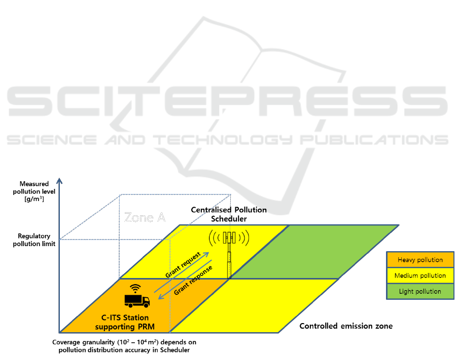
2.1 High-Level Overview
The three pivotal components of PRM are
centralised pollution scheduler, dynamically adapted
pollution grant and reliable low latency pollution
grant signalling. Figure 1 illustrates a typical
example how the PRM scheme works, incorporating
the three pivotal components. A vehicle equipped
with a C-ITS station travelling in the controlled
emission zone is granted the pollution allowance. It
communicates with the centralised pollution
scheduler all the time during its presence in the
zone. Figure 2 presents the data flow diagram with
more details of the system implementing the
proposed scheme.
Figure 1: Example scenario showing pollution scheduler, grant signalling and pollution resource.
VEHITS 2018 - 4th International Conference on Vehicle Technology and Intelligent Transport Systems
284

C-ITS Station (e.g. vehicle)
supporting PRM
Requests pollution grant
Vehicle type and
characteristics, trip plan,
ambient pollutants
concentration,
requested pollution
amount
PRM Scheduler
Calculates difference between
current pollution level and
regulatory limits,
predicts next time slot pollution
level,
works out the available shared
resources and the allowance for
each requesting vehicle
Measured pollution data
Air quality monitoring sites
Collects current atmospheric
pollutant data with sensors
Pollution grant
Weather conditions Meteorological sensors
Figure 2: Detailed flow of data in a system implementation of PRM.
2.2 Pollution Scheduler
The centralised PRM scheduler is similar to
frequency/time resource scheduler in the LTE
mobile telecommunication network entity eNB (base
station). The PRM Scheduler periodically receives
pollution related information (ideally in real time),
from various sources in different locations using
wireless communication (e.g. high throughput low
latency communication may be required for almost
real time pollution information exchange e.g.
provided by 5G systems):
Generated pollution (e.g. [g] or [g/s]) -
vehicles, power stations, business premises,
households, and other sources
Pollution measurements (e.g. concentration
limit [g/m
3
]) - from available pollution sensors
in the zone (e.g. reusing pollution stations in
cities or pollution sensors integrated with
pollution sources i.e. vehicles)
Weather conditions – factors impacting
pollution dispersion (e.g. wind direction and
strength, temperature)
Based on the received feedback aggregated from
all sources, PRM Scheduler could build a precise
pollution concentration map [g/m
3
] in spatial domain
and model the pollution dispersion in time domain
(e.g. caused by the wind) and use the interpolation
where the information is not available. Scheduler
tracks pollutant concentration changes in a spatial
domain, possibly with a cubic meter used as a
concentration unit mapped to a square meter on the
map to render the isometric representation (see
Figure 1), and compares it with the regulatory limit
(concentration limit per second rather than hour or
similar needs to be defined). The main goal of the
scheduler is to keep the actual mass of the pollutant
per cubic meter (or similar unit) at the precise
location during a predefined period of time below
the regulatory pollutant limit (soft or hard) while
‘fairly’ sharing the observable difference i.e. [g] or
[g/s] between the users of the common resource by
using pollution grants. The actual definition of
fairness in this context could be an implementation
specific and could be related to the communicated
characteristics of the pollution source (see pollution
grant and signalling described in next sections for
more details).
2.3 Pollution Grant
PRM controls the amount of generated pollution in a
spatial domain by scheduling pollution grants to
pollution sources (e.g. vehicles or other stationary
objects). Pollution grant controls how much
pollution (mass) the source could generate per
spatial unit or air volume (in cubic meters) in its
location to keep the concentration level below the
limit. Scheduling decision frequency may depend on
the frequency of received pollution feedback (in
seconds or tens of seconds). Scheduling grant could
be communicated to sources by a wireless
communication technology (e.g. cellular, V2X). The
communication does not necessarily need to happen
in the controlled emission zone. It can be initiated by
a vehicle outside of the zone to facilitate the trip
planning when in the zone. If inside the zone, every
pollution source after receiving the grant
continuously monitors its emissions and makes sure
its pollution emission does not exceed the grant to
avoid consequential penalty from the local
environment authority (enforcement).
The pollution source takes into account its
characteristics and adapts its behaviour to use the
grant efficiently to reduce emissions:
Controlled Emission Zone Pollution Resource Management in 5G C-ITS
285

Mobile vs. static source - Vehicle will receive
different grant as it moves to different location
in the zone, while power stations will receive
updated grant as time proceeds
Behaviour change - Vehicle limits maximum
speed, reduces engine power (e.g. switches off
some engine cylinders), switches to electric or
alternative power source (hybrid)
Pollution grant validity could be limited by
a configurable timer
mobile pollution source (vehicle) leaving
predefined area (location based)
new grant received from the pollution
scheduler (update)
2.4 Pollution Grant Signalling
Pollution grant signalling is based on a request
message(s) from the pollution source (grant request)
and response message(s) from the pollution
scheduler (grant approval). Figure 3 illustrates the
corresponding message sequence diagram.
Pollution Request Message could be sent when
the current pollution grant was used (grant invalid)
or periodically and could include parameters which
the scheduler takes into account:
Measured ambient pollutant concentration at
source area location (if available). Source area
location size could vary (meters to hundreds
of meters) depending on the granularity of the
pollution resource definition in PRM
Scheduler (increased granularity may increase
amount of exchanged data and as a result, high
performance wireless communication
providing high throughput and low latency
may be required e.g. based on 5G system)
Amount of planned emitted pollution
requested to be approved by the scheduler,
e.g. based on other in zone trip related factors
current location
distance to be travelled in the zone
planned time spent in the zone
average speed
capability to temporarily reduce
emissions (e.g. alternative engine power
source, reduced engine power)
Scheduler Response Message based on the
knowledge of pollution resource usage in current
location (pollution emission amount-mass to stay
below the regulatory limit) may grant either
a full pollution amount requested by the
source or
a reduced pollution amount (local pollution
high or close to the limit) to keep the overall
concentration below the limit
Overriding pollution scheduler grant decision
(generating more pollution than approved) is
possible but
must be communicated back to the scheduler
(by using another message or piggybacked on
the next grant request message from the
vehicle) to make sure the scheduler controls
the overall pollution
may generate additional charging fee (“pay as
you pollute” principle etc.)
3 ALTERNATIVE
IMPLEMENTATIONS
3.1 Distributed Pollution Scheduler
within MEC Architecture
Pollution scheduler can be implemented in a
distributed architecture – centralised pollution
scheduler controlling predefined geographical area
can communicate (e.g. wirelessly) with other
schedulers in the neighbourhood geographical areas
to share information and coordinate the pollution
level changes at the boundaries (i.e. due to the wind
impact). This makes PRM a suitable use case for
Mobile Edge Computing (or Multi-access Edge
Computing, MEC) (ETSI, Multi-access Edge
Computing, retrieved 2017). MEC has a primary use
case of Active Device Location Tracking (Huawei et
al. 2014). PRM can be integrated with the MEC use
case using the location service. Figure 4 illustrates
an example of the PRM implementation within the
MEC network architecture. The example assumes a
5G network deployment scenario, to leverage
superior 5G capability, where the PRM can be
regarded as a user scenario of massive Machine
Type Communication (mMTC). The PRM
application may be also using 4G LTE or 3G UMTS
technologies for communication.
To allow continuous and almost real time
information exchange (low latency), the pollution
scheduler functionality can be implemented as a new
application integrated into cellular base station
architecture (5G gNB or 4G LTE eNB) in parallel to
its normal radio resource management function
VEHITS 2018 - 4th International Conference on Vehicle Technology and Intelligent Transport Systems
286
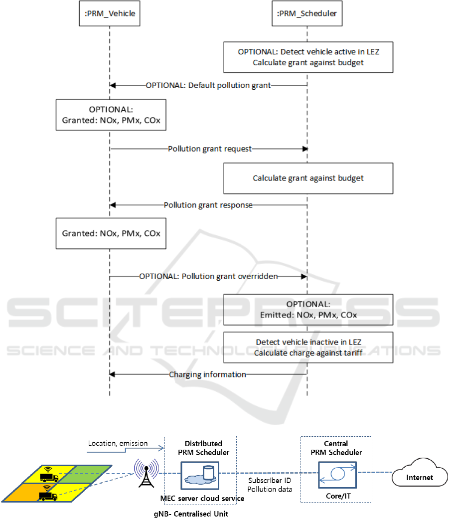
Figure 3: Pollution grant signalling scenario example.
Figure 4: Example of PRM implementation within MEC network architecture.
supported by high performance wireless
communications. The new application is denoted as
PRM Scheduler in Figure 4. It will use the cloud
resources centralised and provided at gNB-
Centralised Unit (gNB-CU, or Baseband Unit, BBU)
in a typical 5G Centralised Radio Access Network
(or Cloud RAN, C-RAN). On the vehicle side, each
5G User Equipment (UE) is also a C-ITS Station,
communicating directly with a Distributed Unit
(gNB-DU, or Remote Radio Head, RRH).
Periodically, the vehicle will send its location
and polluting emission information to the gNB and
Controlled Emission Zone Pollution Resource Management in 5G C-ITS
287

the data is centralised and locally pre-processed at
the gNB. It is worth also noting, although not
depicted in Figure 4, that the sensed atmospheric
environmental pollution data can also be collected in
the same way as the vehicle data is done.
The controlled emission zone supported by a low
latency radio access and the PRM application
available at the network edge coincides with the 5G
small cell network deployment in a geographical
sense, providing a great potential for highly efficient
pollution controlled scheme in the local
neighbourhood of the small cell. Depending on the
PRM deployment policy and the controlled emission
zone granularity, the small cells can be aggregated
or divided to be mapped into each controlled zone.
The benefit of this mapping is that the pollution
resource quota can be allocated to each distributed
PRM scheduler residing on the gNB-CU. The
scheduler monitors the pollution level in its local
zone and schedules the grants to each vehicle in the
zone, under the coordination of the central PRM
service, which is located in the Core network.
The gNB edge processed information is then
filtered and the much reduced refined information is
exchanged with the central PRM service, which will
coordinate the whole controlled wider area emission
zone entailing all the distributed PRM scheduler
controlled zones. The information between the C-
RAN and Core Network central service comprises of
the subscriber ID of the vehicle, pollution data in the
controlled emission zone and other environmental
information. That information will be logged into
and updated at the central service user account and
zone database. In the opposite direction, the central
service will coordinate the pollution resource grant
and synchronise all the distributed user data all over
the zone. To summarise, the ‘centralised unit’ of
gNB centralises all the resources in the 5G C-RAN,
whilst PRM schedulers are distributed into each C-
RAN, under the coordination of the central service.
3.2 Pollution Grant Signalling
It is also possible that the same default pollution
grant value is first automatically broadcasted to all
users (e.g. this may be implemented as part of the
system information broadcast messaging typically
used in the mobile cellular networks if the pollution
scheduler is integrated with the 5G base station,
gNB) and then an additional amount is only
requested by those users who found the grant
insufficient for their use (see Figure 3).
The proposed pollution grant signalling can be
then implemented in a new pollution supporting
protocol running between the base station scheduler
application and corresponding applications
integrated with the pollution sources. This may be
realized in the future Internet of Things / Smart City
architectures by the broader integration of the
pollution monitoring and control network (sensors
and monitoring stations) with the communication
infrastructure (cellular wireless network).
4 DISCUSSION AND
CONCLUSIONS
PRM defines the pollution as a controllable and
shareable user resource by using regulatory limit in
space and time. The difference between the
regulatory pollutant limit and the actual mass of the
pollutant per cubic meter at a precise location during
a predefined period of time is viewed as the
pollution resource. If the pollutant concentration is
under the limit, then the resource is available and the
air can be polluted in a controllable manner with
PRM. If the concentration is above the limit, then
the resource is in deficit and as a result, immediate
measure should be taken with PRM.
PRM Scheduler provides proactive continuous
pollution emissions management based on the
central entity which aims to minimise the difference
between a regulatory pollutant limit and the actual
mass of the pollutant per cubic meter at a precise
location during a predefined period of time.
PRM provides continuous proactive control and
sharing of the pollution resource to be used between
users in a fairer way by means of the pollution grant.
Each vehicle or polluting source equipped with
communication capabilities and PRM functionalities
contributes to the fairer pollution management and
charging scheme. The flat charging will be replaced
with a “pay as you pollute” approach with an
accurate customised charging. According to the
vehicle type, the polluting grant is adjusted and
allocated fairly to each vehicle / source.
PRM signalling is based on a user asking for the
pollution emission allowance in advance (grant
request message) and receiving the pollution grant
(response). The polluting vehicle may be informed
about the possible consequence of travelling through
the the controlled emission zone at the trip planning
stage even before it enters the zone.
In summary, there are three novel elements
proposed in this paper related to the pollution:
Grant - defining pollution as a controllable
and shareable user resource by using
VEHITS 2018 - 4th International Conference on Vehicle Technology and Intelligent Transport Systems
288

regulatory limit in space/time (i.e. difference
between regulatory pollutant limit and the
actual mass of the pollutant per cubic meter at
a precise location during a predefined period
of time)
Scheduler - proactive continuous pollution
emissions management based on the central
entity which aims to keep the difference
between regulatory pollutant limit and the
actual mass of pollutant per cubic meter at a
precise location during a predefined period of
time
Signalling - based on a user asking for the
pollution emission allowance in advance
(grant request message) and receiving the
pollution grant (response).
Furthermore, the other innovative aspect is the
continuous, proactive and dynamic control of the
pollution in the controlled emission zone (e.g. in a
large city) based on the current air quality, weather
forecast and polluting sources status. The dynamic
control through the interaction between the polluting
source (e.g. vehicle) and the centralised PRM
scheduler is achieved by restricting the pollution
allowed for each vehicle. This can be enforced by
charging users extra for overusing the grant and
causing excessive tailpipe emissions. Instead of
unfairly punishing some fraction of the vehicles in
the zone (typically heavy goods vehicles or buses),
every polluting source is involved in the scheme,
which takes the environmental awareness to a new
level. Although th proposed PRM scheme may
require some infrastructure investments, it can
improve the fairness, effectiveness and efficiency of
the controlled emission zones in cities. Finally, the
proposed scheme extends the 5G communications
technology application to the new vertical domain of
the pollution control by leveraging the capabilities of
5G to provide the continuous air pollution control in
the future Internet of Things and Smart Cities
environments.
REFERENCES
Air Quality Expert Group, 2004. Nitrogen Dioxide in the
United Kingdom Summary Report. Published by the
Department for Environment, Food and Rural Affairs.
European Commission, retrieved 2017.
http://urbanaccessregulations.eu/low-emission-zones-
main.
European Telecommunications Standards Institute (ETSI),
retrieved 2017. http://www.etsi.org/technologies-
clusters/technologies/automotive-intelligent-transport.
ETSI, Multi-access Edge Computing, retrieved 2017.
http://www.etsi.org/index.php/technologies-
clusters/technologies/multi-access-edge-computing.
Huawei, et al. 2014. Mobile-Edge Computing –
Introductory Technical White Paper. Published by
ETSI.
Natalie Chapman (editor), 2010. An FTA compliance
guide: Greater London Low Emission Zone, Freight
Transport Association Limited report, Edition 3.
Paul Watkiss, 2003. The London Low Emission Zone
Feasibility Study: Phase 2, a summary of the main
report to the London LEZ steering group, AEA
Technology Environment.
Transport and Travelling Research Ltd., 2006. Air Quality
Impacts of Low Emission Zones v1.0, Institute of Air
Quality Management, IAQM report.
Transport for London, retrieved 2017.
https://tfl.gov.uk/modes/driving/low-emission-zone.
Transport for London, retrieved 2017.
https://tfl.gov.uk/modes/driving/ultra-low-emission-
zone.
Viviane Weinmann, 2014. Low Emission Zone (LEZ) -
Vehicle Travel Restriction to Improve Air Quality in
Inner Cities, Deutsche Gesellschaft für Internationale
Zusammnarbeit (GIZ) GmbH report.
Controlled Emission Zone Pollution Resource Management in 5G C-ITS
289
