
A Multi-Channel Software Decoder for the LoRa Modulation Scheme
Pieter Robyns
1
, Peter Quax
2
, Wim Lamotte
1
and William Thenaers
3
1
Hasselt University - tUL, Expertise Centre for Digital Media, Martelarenlaan 42, 3500 Hasselt, Belgium
2
Hasselt University - tUL - Flanders Make, Expertise Centre for Digital Media, Martelarenlaan 42, 3500 Hasselt, Belgium
3
Hasselt University - tUL, Martelarenlaan 42, 3500 Hasselt, Belgium
Keywords:
LoRa, Software Defined Radio, PHY Layer, Decoder, Signal Processing, Reverse Engineering.
Abstract:
LoRa is a recently introduced modulation scheme specifically designed for Low-Power Wide-Area Networks.
In this paper, we provide the first detailed and complete description of the LoRa PHY layer, and present a
novel methodology for detecting and decoding LoRa frames using Software Defined Radios. Our proposed
decoding approach can efficiently decode multiple channels simultaneously in software due to an invariance
towards the signal frequency. Hence, our approach also removes the need for correcting frequency offset errors
imparted by the transmitter or receiver. We have evaluated our decoding technique in a lab setup using three
Software Defined Radios (USRP B210, HackRF, and RTL-SDR) and three commercial off-the-shelf hardware
LoRa transceivers (Microchip RN2483, HopeRF RFM96, and Semtech SX1272). We show that our decoder
is fully compatible with all configurations of the RN2483 and SX1272, achieving an overall packet error rate
of 0 for a signal-to-noise ratio of 20 dB. The source code of the decoder and datasets used in the evaluation
are made available publicly.
1 INTRODUCTION
In coming years, the industry is expected to show
an increased interest in Low-Power Wide-Area Net-
works (LPWANs) and their applications, such as
smart metering, location tracking, Wireless Sensor
Networks (WSNs), smart transportation systems and
health monitoring (i-SCOOP, 2017). In such net-
works, several low-power embedded devices are typ-
ically deployed in areas of interest, and perform Ma-
chine to Machine (M2M) communication or interact
with services on the internet in order to complete a
certain computing task. For example, an internet-
connected embedded device may be distributed to in-
dividuals suffering from a cardiovascular disease, so
that their condition can be monitored in real time by
doctors.
The heightened attention for these use cases
sparked the creation of several Physical (PHY)-layer
modulation protocols that are optimized for LP-
WANs, i.e. for low power consumption and long
range communications. Examples of these proto-
cols are LoRa (LoRa Alliance, 2017), Sigfox (Sigfox,
2017), Wi-Fi HaLow (Wi-Fi Alliance, 2017), LTE-
M (3GPP, 2017), and Weightless (Weightless, 2017).
Out of those, LoRa is a proprietary, low-power, and
long-range modulation scheme developed by Cycleo
and acquired by Semtech in 2012 (Semtech, 2012).
It is currently among the more popular protocols,
with numerous gateways already deployed on a global
scale (The Things Network, 2017).
Due to its proprietary nature, specialized hard-
ware is required in order to transmit or receive
LoRa messages. Examples of such hardware are the
SX1272 transceiver developed by Semtech (Semtech,
2015b) and the RN2483 transceiver developed by Mi-
crochip (Microchip Technology Inc., 2015). Both
transceivers expose a serial interface to the user. The
serial interface can only be used to make high level
configuration changes to the LoRa modem, and to
transmit or receive payloads using LoRa modulation.
Hence, the entire PHY layer of these transceivers is
abstracted in hardware, and therefore cannot be ac-
cessed or modified.
Having access to the PHY layer of a wireless
protocol is a desirable feature with many interesting
use cases for research and development. For exam-
ple, recent works have demonstrated the possibility
to fingerprint individual transceivers using only PHY-
layer properties of the signal (Danev et al., 2012;
Robyns et al., 2017; Vo-Huu et al., 2016). This
could be useful for tracking devices or intrusion de-
Robyns, P., Quax, P., Lamotte, W. and Thenaers, W.
A Multi-Channel Software Decoder for the LoRa Modulation Scheme.
DOI: 10.5220/0006668400410051
In Proceedings of the 3rd International Conference on Internet of Things, Big Data and Security (IoTBDS 2018), pages 41-51
ISBN: 978-989-758-296-7
Copyright
c
2019 by SCITEPRESS – Science and Technology Publications, Lda. All rights reserved
41

tection. Another use case could be to perform soft-
ware simulations of the PHY layer, e.g. to determine
the effect of various channel conditions without re-
quiring multiple physical deployments of hardware
transceivers (Ben Hamida et al., 2009; Mezzavilla
et al., 2015). As a final example, enabling modifica-
tions to the PHY layer allows for rapid prototyping
of improvements in terms of security, performance
or reliability (Bloessl et al., 2013a; Sklivanitis et al.,
2016).
In this paper, we provide several contributions that
aim to bring the advantages of PHY-layer access to
the LoRa modulation scheme. First, we provide a
detailed description of the LoRa PHY layer. This
description includes newly added and undocumented
features of the LoRa specification that were reverse
engineered from hardware LoRa transceivers. To the
best of our knowledge, we are the first to provide a
complete and validated overview. Second, we present
our algorithms for the detection, synchronization, and
decoding of raw PHY-layer LoRa frames using Soft-
ware Defined Radios (SDRs). These algorithms in-
clude a novel decoding approach and a novel clock
drift correction approach for LoRa, both implemented
in a complete and open-source software LoRa de-
coder using the GNU Radio framework. Our decoder
is capable of decoding multiple channels simultane-
ously in real time regardless of the frame’s network
identifier, similar to the capabilities of “monitoring
mode” devices in context of 802.11 (Wi-Fi). Finally,
we evaluate our decoder in a lab setup, and show that
it can interoperate with hardware LoRa transceivers,
using only inexpensive Commercial Off-The-Shelf
(COTS) SDRs such as the RTL-SDR.
The structure of this paper is as follows. In Sec-
tion 2, we will present an overview of the LoRa PHY
layer in consideration of our first contribution. Sec-
tion 3 then shows how this knowledge can be applied
to build a complete software LoRa decoder. In addi-
tion, we detail our novel demodulation and clock drift
correction approaches. Our decoder will be compared
in terms of compatibility with existing LoRa hard-
ware and accuracy in Section 4, followed by a discus-
sion of these results. Works related to this research
will be discussed in Section 5. Finally, in Section 6,
we will make concluding remarks and give directions
for future work in this area of research.
2 LoRa PHY LAYER
In order to correctly decode LoRa-modulated data, a
receiver must sequentially perform seven operations
on the PHY layer, namely detection, synchroniza-
tion, demodulation, deinterleaving, dewhitening, de-
coding, and packet construction. A partial descrip-
tion of these operations can be found in several tech-
nical reports released by Semtech (Seller and Sornin,
2014; Semtech, 2015b; Sornin et al., 2015; Semtech,
2015a) and in the paper presented by Goursaud et al.
(Goursaud and Gorce, 2015). However, the informa-
tion contained within these works is insufficient to
build a decoder that can interoperate with real hard-
ware LoRa transceivers. To this end, we have reverse
engineered a RN2483 LoRa transceiver, and provide
the first complete overview of the LoRa PHY layer in
this section.
2.1 Modulation
The LoRa modulation scheme is based on Chirp
Spread Spectrum (CSS) modulation (Goursaud and
Gorce, 2015), and defines a “chirp” as a single sym-
bol (Semtech, 2015a). A standard, unmodulated lin-
ear chirp is called a “base chirp”, and can be math-
ematically described in function of the time t as fol-
lows (Mann and Haykin, 1991):
x(t) = e
i(ϕ
0
+2π(
k
2
t
2
+ f
0
t))
(1)
where ϕ
0
is the initial phase, k is the rate of frequency
change, and f
0
is the initial frequency. Given the
channel bandwidth BW , the parameters f
0
and k are
set so that the frequency increases from f
0
−
BW
2
to
f
0
+
BW
2
over the duration T of the chirp. Hence,
f
0
= −
BW
2
and k =
BW
T
. Here, the chirp duration T
depends on the bandwidth of the signal and on a pa-
rameter called the Spreading Factor (SF) according to
the relation T =
2
SF
BW
(Seller and Sornin, 2014).
Given that x(t + nT ) = x(t) with n ∈ N, an inte-
ger value i ∈ {0,1}
SF
can be modulated onto the base
chirp by introducing a time shift of
ˆ
t = Gray
−1
(i)
T
2
SF
to the signal in Equation 1, where Gray
−1
stands for
a Gray decoding operation (Gray, 1953). This way,
a symbol is essentially quantized into 2
SF
time shift
bins divided over the bandwidth, called “chips”, that
determine i. Upon reception of a modulated chirp
with an unknown time shift x(t +
ˆ
t), the chip value
i can be recovered by sampling the signal at the chip
rate and calculating:
i = Gray(argmax(
FFT( x(t +
ˆ
t) x(t) )
) ) (2)
where x(t) denotes the conjugate of a base chirp,
the operator indicates element-wise multiplication,
FFT(x)
signifies the magnitude of the Fast Fourier
Transform (FFT) of x, and Gray stands for Gray en-
coding. Figure 1 shows an example where a value of
IoTBDS 2018 - 3rd International Conference on Internet of Things, Big Data and Security
42
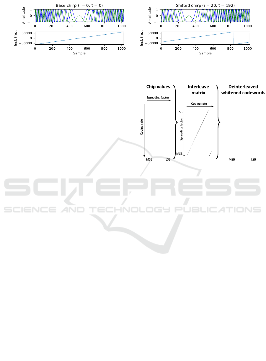
Figure 1: Example of an unmodulated LoRa base chirp and a chirp modulated with i = 20. The top row of figures shows the
time domain complex signal, whereas the bottom row of figures shows the instantaneous frequencies of the signals in Hz.
i = 20 is modulated onto the base chirp, shifting it by
192 samples.
2.2 Interleaving
When using the modulation approach described
above, errors can be introduced due to noise, inter-
ference, and time or frequency offsets. These errors
cause the receiver to derive an incorrect chip value
from the modulated symbol. For example, a burst of
noise could cause the peak of the FFT spectrum to ap-
pear at a different chip, therefore corrupting the entire
chip value.
In order to limit the impact of bursty noise to
a single bit error per symbol, multiple chip val-
ues are stacked together such that a bit matrix
{0,1}
SF×(4+CR)
is obtained. Here, the Coding Rate
(CR) or equivalently, the number of parity bits, can
range from 1 to 4. For example, when using SF = 7
and CR = 4, we obtain a matrix {0,1}
7×8
as shown in
Figure 2. A codeword of 4 +CR bits is then obtained
by diagonally deinterleaving the matrix. As such,
the first chip value provides all first Least Significant
Bits (LSBs) of the codewords, the second chip value
provides all second bits of the codewords, etc. The
direction of the interleaving diagonal appears to be
upwards in practice, in contrast to the LoRa patent
where the interleaving diagonal direction is down-
wards
1
(Seller and Sornin, 2014). Observe that as a
result of the interleaving operation, an entirely cor-
rupted chip value now only affects one bit per code-
word.
The LoRa specification also defines a “reduced
rate” mode, in which the top two rows of the inter-
leaving matrix are discarded. Consequently, the di-
mensions of the matrix become {0,1}
SF−2×(4+CR)
,
yielding two codewords less after deinterleaving. The
discarded rows correspond to the LSBs of the chip
values, which are more prone to errors because they
correspond to narrower frequency bins in the FFT
1
Note that this has no impact on the decoding perfor-
mance.
00000010
01011111
10101111
01011100
00100100
11010001
11000111
01110010
11101000
10100011
00000000
00101110
11010001
11111111
1100100
1101010
0010100
0101010
0001110
1011110
1000111
1100110
Figure 2: Diagonal deinterleaving with SF = 7 and CR = 4.
The bits of the third chip value are shown in bold.
spectrum. Therefore, in reduced rate mode, a de-
creased data rate is traded for an increased robust-
ness to noise. The PHY layer header of LoRa frames
is always transmitted in reduced rate mode, whereas
the payload bytes are only transmitted in reduced rate
mode when SF 11 or SF 12 is used (Semtech, 2015b,
p. 28, 112).
2.3 Coding
After deinterleaving, a number of codewords of size
4 +CR are obtained by the receiver. The codewords
of the frame payload are “whitened” in order to keep
the data Direct Current (DC)-free (Semtech, 2015b,
p. 75). Here, whitening is defined as an opera-
tion where the data is XOR-ed with a 9-bit Linear
Feedback Shift Register (LFSR) after synchroniza-
tion (Semtech, 2015b, p. 72). The used coding al-
gorithm is not explicitly mentioned in the patent or
chipset datasheet (Seller and Sornin, 2014; Semtech,
2015b), leaving this an open choice to the vendor.
For the transceivers we considered during our tests
(see Section 3), we have reverse engineered the cod-
ing scheme and discovered that a modified version of
4/(4 + CR) Hamming coding is utilized in practice.
Hence, each codeword results in 4 data bits when de-
coded, which are subsequently parsed according to
A Multi-Channel Software Decoder for the LoRa Modulation Scheme
43

the LoRa frame structure. In Section 3.3, we will dis-
cuss our approach for decoding the data further.
2.4 Frame Structure
On the PHY layer, LoRa defines a frame struc-
ture with the following sequentially transmitted
fields (Semtech, 2015b, p. 27–29):
• Preamble: A variable-sized sequence of base
chirps that is used for time and frequency synchro-
nization.
• Frame synchronization symbols: Two modu-
lated chirps whose value can be used as a net-
work identifier. A hardware LoRa transceiver will
drop frames containing synchronization symbols
that do not match a preconfigured value.
• Frequency synchronization symbols: Two con-
jugate base chirps followed by a conjugate chirp
with duration
T
4
, which can both be used for fine
frequency synchronization.
• Header (optional): Field containing the payload
length, used data rate, a bit indicating the presence
of a payload Cyclic Redundancy Check (CRC),
and 1-byte header checksum. A CR of 4 is always
used in combination with reduced rate mode for
the header
2
(Seller and Sornin, 2014). The header
can be explicitly transmitted (explicit mode) or
left out of the frame (implicit mode). In the latter
case, the transmitter and receiver must configure
the coding rate and CRC presence bit beforehand.
• Payload: Variable-length field containing the
transmitted Medium Access Control (MAC) layer
data and a 2-byte CRC of this data.
Figure 3 shows an example LoRa signal and its
frame structure.
2.4.1 Header Structure
The exact length and bit order of the fields in the PHY
layer header are not explicitly stated in the specifica-
tions. However, since the transmission of an explicit
header requires a SF of at least 7, and the header is al-
ways transmitted with CR = 4 at a reduced rate (Seller
and Sornin, 2014), the header must fit in an inter-
leaving matrix of {0,1}
(7−2)×8
. Therefore, the header
length must be equal to 5 codewords of 8 bits, i.e. 40
bits in total. Any remaining bits in the interleaving
matrix are used for the payload.
2
Since the header contains the payload length and cod-
ing rate, it is essential that these fields are decoded correctly.
Hence the increased robustness measures.
After decoding, the header data thus has a length
of 40 ·
4
8
= 20 bits or 2.5 bytes. We have experimen-
tally determined that when transmitting data using a
Microchip RN2483 LoRa transceiver, the left-to-right
order of the PHY header is as follows: a single pay-
load Length byte, followed by a nibble for the CR
and MAC CRC presence, the High Nibble (HN) of the
header checksum, and finally the Low Nibble (LN) of
the header checksum
3
. An overview of these fields is
given in Figure 4.
3 SOFTWARE DEMODULATOR
We have implemented the complete PHY layer of
LoRa in software, using the open source GNU Ra-
dio signal processing framework. The source code
of the decoder is publicly available on Github
4
. An
overview of the decoder components is given in Fig-
ure 5.
3.1 Detection and Synchronization
As a first step in the demodulation process, the re-
ceiver must detect the LoRa preamble. To this end,
we exploit the repeating property of the preamble by
using the Schmidl-Cox algorithm, which defines two
quantities P(d) and R(d) as follows (Schmidl and
Cox, 1997):
P(d) =
L−1
∑
m=0
(x
∗
t+m
x
t+m+L
) (3)
R(d) =
L−1
∑
m=0
|x
t+m+L
|
2
(4)
where L is the length of a symbol, t is the sam-
ple index of the complex signal x, and x
∗
denotes the
complex conjugate of x. Next, P(d) and R(d) are used
to calculate a timing metric M(d):
M(d) =
|P(d)|
2
R(d)
2
(5)
The timing metric M(d) essentially calculates a
normalized autocorrelation of length L over two sym-
bols, which will be maximal when two consecutive
symbols are encountered in the signal. An added
advantage of this approach is that any errors intro-
duced by the channel or SDR (e.g. interference,
Carrier Frequency Offset (CFO) and Sampling Fre-
quency Offset (SFO) errors), consistently influence
3
Only the 5 LSBs of the checksum byte appear to be
used in practice.
4
https://github.com/rpp0/gr-lora
IoTBDS 2018 - 3rd International Conference on Internet of Things, Big Data and Security
44
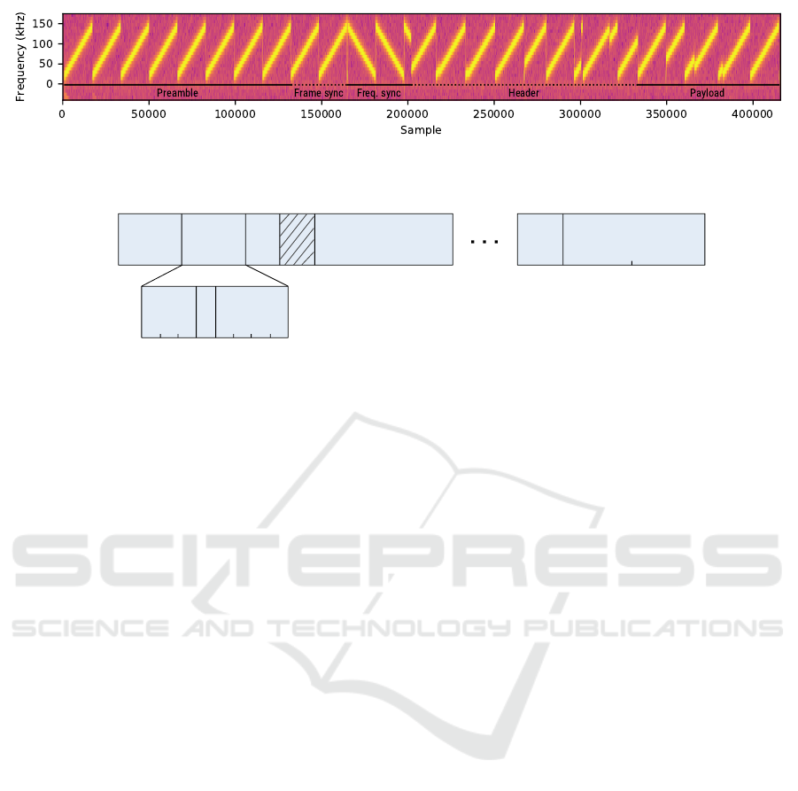
Figure 3: Annotated spectogram of an example LoRa signal transmitted with the RN2483 LoRa transceiver using SF 11 and
CR 5, and received with a USRP B210 SDR.
Length Options
Chk.
(LN)
MAC Payload MAC CRC
Byte 0 1 2 3 n - 1
Bit 7 6 5 4 3 2 1 0
Has
CRC
CR
Chk.
(HN)
n
Figure 4: The fields of the LoRa PHY layer.
both symbols and therefore minimally affect the result
of the correlation. To efficiently compute Equation 3
– 5 in software, we use Single Instruction, Multiple
Data (SIMD) instructions provided by Vector Opti-
mized Library of Kernels (VOLK). Figure 6 (a) shows
the resulting value of the timing metric M(d) when
evaluated for a complex LoRa signal. Observe that
the function reaches a plateau around sample 2,500,
which confirms the presence of a preamble.
Although the Schmidl-Cox algorithm can deter-
mine the presence of a preamble effectively, the
plateau of the timing metric leads to uncertainty as
to the start of the symbol (Schmidl and Cox, 1997).
Wang et al. proposed a variation on the Schmidl-
Cox algorithm where M(d) is subtracted with a time-
delayed version M
2
(d) of itself (Wang et al., 2003).
Consequently, the plateau becomes a peak as shown
in Figure 6 (b), making it possible to take the argmax
of the timing metric in order to estimate the start of the
preamble. However, for LoRa signals, this estimate is
not sufficiently accurate, as shown in Figure 6 (c).
To solve this problem, we only use the standard
Schmidl-Cox metric with a threshold to assert that
the second symbol window is located anywhere in-
side the preamble. Next, we generate an ideal, lo-
cally synthesized base chirp and calculate its instan-
taneous frequency ω
l
(t), as well as the instantaneous
frequency of the received LoRa signal ω(t). Finally,
a sliding window normalized cross-correlation is per-
formed, and the index of the maximum value of the
cross-correlation is chosen as the starting point of the
symbol:
symbol start = argmax
i∈{0,1,...L}
(ω
l
? ω)(i) (6)
The result of this operation is visualized in Fig-
ure 6 (d). Note that by performing the cross-
correlation on the instantaneous frequency of the sig-
nals instead of their complex values, any CFO er-
rors imparted by the channel are automatically miti-
gated similarly to the Schmidl-Cox algorithm. Thus,
the accuracy of the synchronization is not affected
by the CFO. On the contrary, if one would consider
the complex-valued signals, a correction of frequency
errors introduced by the channel and SDR would
have to be performed before the signal can be cross-
correlated with the locally synthesized chirp.
At last, in order to verify the correctness of the
time synchronization, we threshold against the max-
imum correlation coefficient between the instanta-
neous frequency of the locally generated chirp and re-
ceived chirp. The LoRa frame is rejected if the corre-
lation coefficient falls below a certain tolerance value,
since this indicates a failed synchronization or false
positive during the detection stage (see Section 3.1).
3.2 Demodulation
Following synchronization, the receiver can demodu-
late the chip values as discussed in Section 2. How-
ever, the FFT-based demodulation approach specified
in (Seller and Sornin, 2014) is sensitive to frequency
offset errors, which cause the magnitudes of the FFT
(and thus the chip values) to shift. Therefore, an ac-
curate frequency synchronization is required. Fur-
thermore, this synchronization must be applied for
each LoRa channel separately in order to fulfill our
requirement of multi-channel decoding motivated in
Section 1.
Since channelization and separate processing of
each channel is an expensive operation to perform in
A Multi-Channel Software Decoder for the LoRa Modulation Scheme
45
Hardware
SDR
Sampling &
Filtering
Antenna
Preamble
detection
Synchronization
ModulationInterleavingWhitening
Coding
Host
Software
Receive chain specific
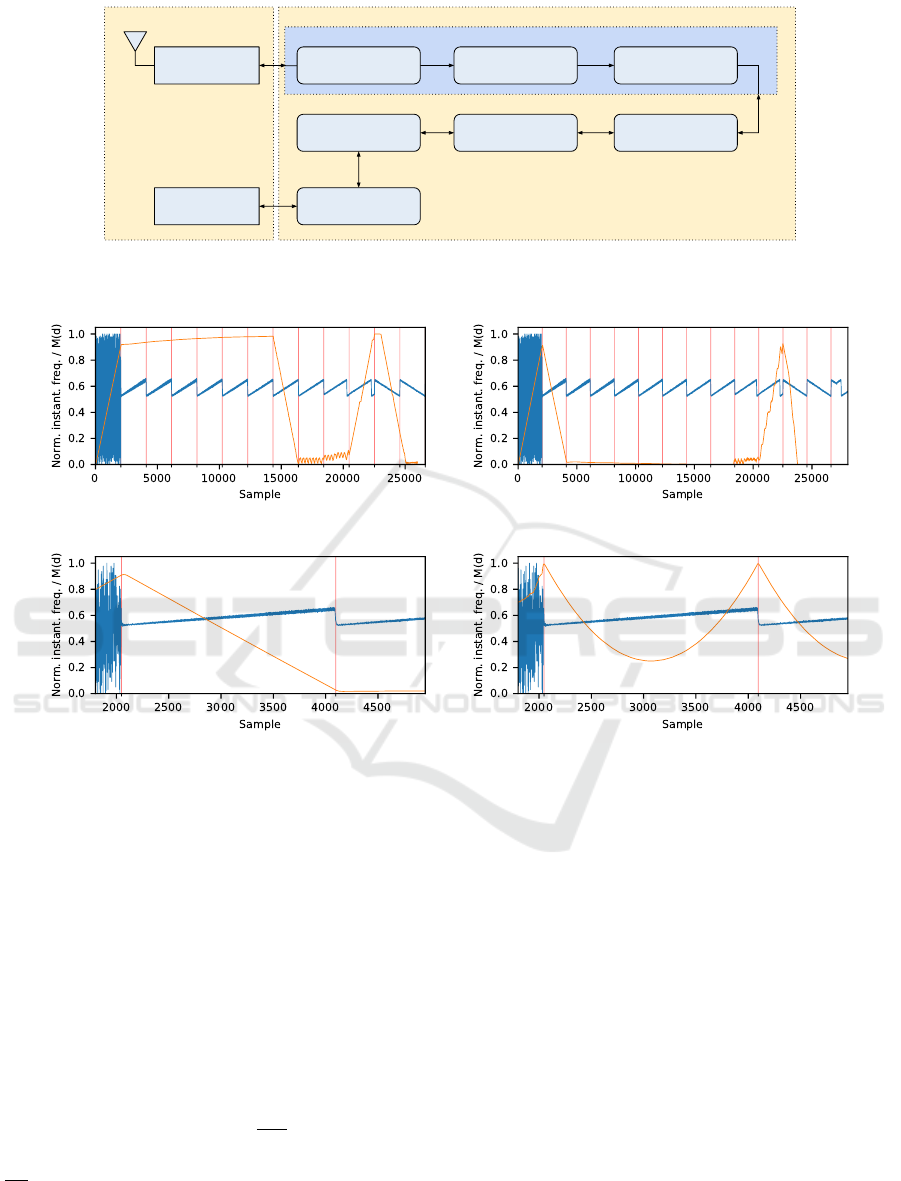
Figure 5: An overview of the LoRa decoder components, showing the various logical processing blocks required for the
transmission and reception of baseband I/Q samples with an SDR.
(a) Schmidl-Cox (b) Modified Schmidl-Cox
(c) Modified Schmidl-Cox (zoomed) (d) Our sync. algorithm (zoomed)
Figure 6: Normalized instantaneous frequency of a LoRa signal (blue) and the normalized Schmidl-Cox timing metric M(d)
(orange). The vertical red lines indicate the symbol window length L. In (a), the timing metric reaches a plateau upon
encountering two consecutive and identical symbols. A modified version (b) results in a single peak at the first symbol, but is
insufficiently accurate to determine the start of the preamble (c). Our synchronization using the normalized cross-correlation
of the instantaneous frequency (d) shows a sharp peak at the start of each preamble symbol.
software, we have developed a novel demodulation
technique that is independent of the frequency. Our
technique removes the need for frequency corrections
and allows to decode LoRa frames in real time on all
channels and without additional processing overhead,
but at the cost of a reduced robustness compared to the
FFT approach discussed in Section 2.1. This tradeoff
will be discussed in Section 4.
In our methodology, we first calculate the instanta-
neous angular frequency ω[t] =
dϕ[t]
dt
. We then smooth
and decimate ω[t] with a constant decimation factor of
s
f
T
2
SF
, where s
f
is the sampling frequency. This ensures
that the number of samples in ω[t] is equal to 2
SF
.
Subsequently, the digital gradient of f is calculated:
D
t
[ω[t]] = ω[t + 1] − ω[t] (7)
This operation can be intuitively seen as a high
pass filter on the instantaneous frequency, or as the
second order derivative of the phase. Since the fre-
quency of a base chirp linearly increases with k, i.e.
ω(t) = kt + f
0
, its derivative ω
0
(t) is equal to k. For
a modulated chirp however, D
t
will exhibit a sharp
peak at the transition from high to low frequency. If
present, the position of the peak indicates the time
shift
ˆ
t. Otherwise, the time shift is equal to 0 (base
chirp).
IoTBDS 2018 - 3rd International Conference on Internet of Things, Big Data and Security
46

p0 p1 p3 p2 d3 d2 d1 d0
1 1 0 1 0 0 0 1
p0 p1 d3 p2 d2 d1 d0 p3
1 1 0 1 0 0 1 0
Parity:
Data:
0111
0001
LSB
MSB
Bit 7 6 5 4 3 2 1 0
Figure 7: The bit mapping of an example Hamming code-
word used in LoRa (top) to a standard Hamming code (bot-
tom), for a CR of 4 and data 0x1.
3.3 Decoding
In the decoding stage, the chip values are deinter-
leaved to form codewords of 4 +CR bits. The first 8
codewords of a frame can be directly decoded to form
the PHY-layer header. On the other hand, we found
that the payload symbols must be dewhitened first.
Although the datasheet released by Semtech specifies
the usage of a 9-bit LFSR, a different and unknown
whitening LFSR appears to be implemented in prac-
tice (Knight, 2016; Blum, 2017). We have reverse en-
gineered the whitening sequence using the following
approach.
If we represent the whitening process as c
( j)
w
=
c
( j)
⊕ w
( j)
with c
w
the whitened codeword, c the un-
whitened codeword, w the output of the LFSR and j
the byte index, we can determine w
( j)
by transmit-
ting a known codeword c
( j)
and calculating w
( j)
=
c
( j)
w
⊕c
( j)
. For example, a payload with all codewords
set to zero will result in w
( j)
= c
( j)
w
⊕0, or the whiten-
ing sequence itself. Hence, after transmitting a pay-
load consisting of all zeros, the resulting whitening
sequence can be retrieved and stored in a lookup ta-
ble.
With knowledge of the whitening sequence w,
the last step after dewhitening is to perform Ham-
ming decoding on the codewords. We found that in
LoRa transceivers, the data bits are positioned at bit
indices 0, 1, 2, and 3 of a byte. This is in contrast
to standard Hamming which uses indices 1, 2, 3, and
5 as data bits. This mapping is graphically depicted
in Figure 7. After extraction of the data bits and er-
ror correction or detection based on the present parity
bits, the demodulator outputs the data to a UDP socket
for further processing by higher-layer applications.
3.4 Clock Drift Correction
The crystal oscillators in the SDR and LoRa
transceiver inherently have a relative and unknown
clock drift, which causes a loss of synchronization
over time. This is especially problematic for long pay-
loads in combination with higher SFs due to the sym-
bol lengths in these configurations. To correct for the
clock drift, we propose a blind estimation technique
5
that exploits oversampling of the transmitted signal at
a rate of N.
As a first step, our technique requires an accurate
initial acquisition of the timing offset using the algo-
rithm discussed in Section 3.1. Assuming that the
timing error per symbol ∆t, measured in number of
samples, satisfies the inequality |∆t| <
N
2
, we can de-
termine ∆t as follows:
1. The symbol is demodulated normally as described
in Section 3.2, in order to obtain the chip value i
and the time shift
ˆ
t.
2. At the receiver, a locally generated ideal upchirp
is now modulated using i, which introduces a time
shift of
ˆ
t
l
on the local signal (see Section 2).
3. Since the locally generated chirp is not subject to
relative clock drift, the timing error is: ∆t =
ˆ
t
l
−
ˆ
t.
The receiver can now correct
ˆ
t by adding a time
offset of ∆t to the received signal.
Note that if the timing error for a single sym-
bol |∆t| ≥
N
2
, the decoder will incorrectly determine
the chip value i and therefore propagate the error to
subsequent symbols. For this reason, we interpo-
late from
ˆ
t to
ˆ
t + ∆t rather than setting the value di-
rectly. This mitigates the effect of single-symbol de-
modulation errors on the clock drift correction algo-
rithm. A higher oversampling rate N allows for more
fine-grained timing error corrections at the cost of in-
creased processing overhead.
4 EVALUATION
Our demodulator was evaluated in a lab setup us-
ing different SDR models and LoRa hardware.
More specifically, we have performed tests with the
RN2483, SX1272 and RFM96 configured as trans-
mitters and the Ettus B210 USRP, HackRF, and RTL-
SDR configured as receivers. Each test was per-
formed using a carrier frequency of 868.1 MHz, a
sample rate of 1 Msps, and a distance between the
transmitter and receiver of about 1 meter. The source
code required for reproducing the test results and
datasets from the accuracy experiments are publicly
available on Github
6
.
5
Although the LoRa patent specifies the usage of “pilot”
symbols for tracking timing (Seller and Sornin, 2014), these
symbols appear to be absent in practice. We therefore need
to make use of blind estimation techniques.
6
https://github.com/rpp0/lora-decoder-paper
A Multi-Channel Software Decoder for the LoRa Modulation Scheme
47

4.1 Compatibility
In a first experiment, we evaluated the compatibil-
ity of our decoder with hardware LoRa transceivers.
Here, we used the USRP as the receiver and RN2483,
SX1272 and RFM96 as transmitters. The com-
patibility was evaluated by transmitting the pay-
load “0123456789abcdef” 100 times for all possible
combinations of CR and SF, and checking the number
of correctly decoded frames. A configuration is con-
sidered compatible when transmitted LoRa frames are
consistently correctly decoded under ideal channel
conditions and a high Signal-to-Noise Ratio (SNR).
The results of this experiment are shown in Ta-
ble 1. Observe that the only incompatible con-
figurations are SF 11 and SF 12 for the RFM96
transceiver. After a manual inspection, we found that
the cause of this incompatibility is due to the fact that
the RFM96 transceiver does not enable the reduced
data rate mode as mandated in the LoRa specifica-
tion (Semtech, 2015b, p. 28). In fact, even when
transmitting a message from the RFM96 to either the
hardware SX1272 or RN2483 hardware transceivers,
the resulting frame is always corrupted for SF 11 and
SF 12. When we manually disabled reduced data
rate mode in our decoder, we achieved full compat-
ibility with all devices. This confirms that the is-
sue lies within the hardware implementation of the
RFM96, and shows that our decoder can be used to
troubleshoot incompatibilities between LoRa devices
from different vendors.
4.2 Accuracy
In the accuracy experiments, we measured the Packet
Error Rate (PER), i.e. the ratio of erroneous packets
received over the total number of packets transmitted,
for a fully compatible transmitter configured with SF
7 and CR 4. We also artificially introduce two types
of channel distortions to the I/Q signal at the receiver,
namely Gaussian white noise and CFOs.
Figure 8 shows the effect of artificial Gaussian
white noise on the decoding accuracy when using a
SF of 8 and CR of 4, the RN2483 as a transmitter,
and the HackRF, RTL-SDR and USRP SDRs as re-
ceivers. The receivers were each configured with a
receive gain of 10 dB, and the transmit power of the
RN2483 was configured to 1 dB. Note that even so,
the effective receive gain between the SDRs differs
due to their different hardware and antenna designs.
From the figure we can derive that a SNR around 20
dB is at least required in order to obtain a PER of 0
for all SDRs.
In Figure 9 (a), we used the USRP to add Gaus-
Figure 8: The effect of artificial Gaussian white noise on
the accuracy of the decoder. The PER of our decoder for all
evaluated SDRs approaches 0 around a SNR of 20 dB.
sian noise at the transmitter instead of the receiver
in order to compare our decoder (RTL-SDR) with a
hardware LoRa transceiver (RN2483). For this ex-
periment, both receivers were placed at an equal dis-
tance from the USRP, and 100 frames with a payload
of “0123456789abcdef” were transmitted to calcu-
late the PER. Observe that the RN2483 is still ca-
pable of receiving frames well below the noise floor,
whereas our decoder stops receiving any frames at 0
dB SNR. At this point, the transient of the gradient
cannot be detected by our gradient-based decoding al-
gorithm due to the presence of excess noise.
On the other hand, when we introduce a CFO in-
stead of Gaussian noise to the transmitted signal, our
decoder outperforms the hardware for a CFO larger
than 50 kHz or when transmitting at a different chan-
nel as shown in Figure 9 (b)
7
. The hardware device
must be retuned in order to capture frames from a dif-
ferent channel, whereas our decoder is capable of cap-
turing frames from multiple channels simultaneously.
Based on these observations, we conclude that our
decoding technique essentially trades flexibility (i.e.,
being able to decode multiple channels simultane-
ously at no additional cost) for an increased sensitivity
to Gaussian noise. Although the increased sensitivity
to noise reduces the functioning range of the receiver,
the flexibility of our approach allows for building a
fully compatible and multi-channel LoRa monitoring
device at a very low cost. We therefore believe our
software decoder is especially suited for research pur-
poses. In fact, in a previous work, the authors have
used the discussed techniques to extract PHY-layer
features from LoRa signals and fingerprint individual
transceivers (Robyns et al., 2017).
7
Note that at 125 kHz, the PER of the RN2483 decreases
momentarily back to 0.2. This could possibly be explained
by the CFO causing the FFT peak to wrap back to an ap-
proximately correct position.
IoTBDS 2018 - 3rd International Conference on Internet of Things, Big Data and Security
48
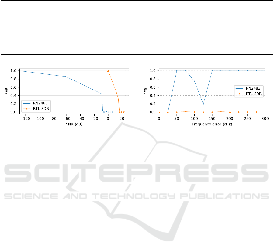
Table 1: Results of the compatibility experiment, showing the LoRa transceivers and configurations for which our decoder
was able to successfully decode frames.
Transceiver
SF 7, CR 1
SF 7, CR 2
SF 7, CR 3
SF 7, CR 4
SF 8, CR 1
SF 8, CR 2
SF 8, CR 3
SF 8, CR 4
SF 9, CR 1
SF 9, CR 2
SF 9, CR 3
SF 9, CR 4
SF 10, CR 1
SF 10, CR 2
SF 10, CR 3
SF 10, CR 4
SF 11, CR 1
SF 11, CR 2
SF 11, CR 3
SF 11, CR 4
SF 12, CR 1
SF 12, CR 2
SF 12, CR 3
SF 12, CR 4
Implicit
Custom module (RN2483) 3 3 3 3 3 3 3 3 3 3 3 3 3 3 3 3 3 3 3 3 3 3 3 3 N/A
Pycom LoPy (SX1272) 3 3 3 3 3 3 3 3 3 3 3 3 3 3 3 3 3 3 3 3 3 3 3 3 N/A
Dragino Pi HAT (RFM96) 3 3 3 3 3 3 3 3 3 3 3 3 3 3 3 3 7 7 7 7 7 7 7 7 3
*
*
Only device in our possession with an API for sending frames in implicit mode. A custom header appears to be transmitted by the RFM96 in this mode.
(a) (b)
Figure 9: Comparison between the RTL-SDR using our software decoder versus a hardware RN2486 LoRa transceiver in
terms of resistance to Gaussian noise (a) and resistance to frequency offset errors (b). Due to the properties of our gradient-
based decoding algorithm, our decoder is shown to be unaffected by frequency errors at the cost of a significantly higher
sensitivity to Gaussian noise compared to the RN2483.
5 RELATED WORK
A high-level system architecture overview of LoRa is
given by Centenaro et al. (Centenaro et al., 2016).
Sikken has provided a general overview of the
LoRa frame structure and decoding stages, but does
not discuss the low level details of the modula-
tion (Sikken, 2017). Goursaud et al. have provided a
detailed and formal analysis of LoRa modulation, but
do not discuss the interleaving, whitening and cod-
ing (Goursaud and Gorce, 2015).
A first complete analysis of the LoRa PHY was
presented by Knight (Knight, 2016). However, in
their work, it is assumed that the dewhitening op-
eration is performed before deinterleaving, that the
header is whitened, and that a different interleaving
pattern is used than the diagonal interleaving speci-
fied in (Seller and Sornin, 2014). Based on our own
experiments, we concluded that these claims are in-
accurate. A decoder named gr-lora was developed
based on their analysis, but appears to only be able
to decode short frames transmitted without a header.
We believe this limitation is the result of errors made
during their reverse engineering process.
Other software LoRa decoders for SDRs have
been developed by Blum et al. (Blum, 2017) and
by Project Sdrangelove (RTL-SDRangelove, 2017).
However, we were unable to decode any frames trans-
mitted by hardware LoRa transceivers using these de-
coders. Finally, at the time of writing, none of the
decoders in other works have developed a clock drift
correction algorithm for decoding long LoRa frames.
Besides work on LoRa, GNU Radio based de-
coders have previously been developed to decode pro-
tocols such as Global System for Mobile Communi-
cations (GSM) (Alyafawi et al., 2014; Krysik, 2017),
Long Term Evolution (LTE) (Demel et al., 2015), and
802.11 (Bloessl et al., 2013b; Vo-Huu et al., 2016)
using SDRs.
6 CONCLUSIONS AND FUTURE
WORK
In this paper, we have provided an in-depth exami-
nation of the LoRa PHY layer, and demonstrated our
open source LoRa software decoder, which is imple-
mented using the GNU Radio framework. Our de-
coder can be used in real time with inexpensive SDRs
such as the RTL-SDR, and is able to interoperate with
existing LoRa transceivers. A set of frequency in-
variant techniques for the detection, demodulation,
A Multi-Channel Software Decoder for the LoRa Modulation Scheme
49

and clock drift correction of LoRa frames were intro-
duced, which result in the capability to decode mul-
tiple channels simultaneously in real time, at the cost
of an increased sensitivity to noise compared to COTS
LoRa radios. Our evaluation shows that a SNR of at
least 20 dB is required for the PER to approach 0.
In future work, a number of aspects of the decoder
can be further improved upon. Most importantly, the
robustness of the decoder could be improved to ap-
proach the performance of LoRa hardware, which is
a challenging problem given the limited available re-
sources and timing constraints in real-time software
decoders. Another scenario that was not yet consid-
ered in this work is the handling of collisions between
LoRa frames, which could occur on a busy channel.
Finally, we hope that the access to the PHY layer pro-
vided by our work will support the development of
future improvements in context of LoRa.
ACKNOWLEDGEMENTS
This research was funded by a Ph.D. Grant of the
Research Foundation Flanders (FWO), grant number
1S14916N.
REFERENCES
3GPP (2017). LTE Release 13. http://www.3gpp.org/
release-13. Accessed: 9 October 2017.
Alyafawi, I., Dimitrova, D. C., and Braun, T. (2014). Real-
time passive capturing of the GSM radio. In IEEE
International Conference on Communications (ICC),
pages 4401–4406. IEEE.
Ben Hamida, E., Chelius, G., and Gorce, J. M. (2009). Im-
pact of the physical layer modeling on the accuracy
and scalability of wireless network simulation. Simu-
lation, 85(9):574–588.
Bloessl, B., Leitner, C., Dressler, F., and Sommer, C.
(2013a). A GNU radio-based IEEE 802.15. 4 testbed.
12. GI/ITG KuVS Fachgespr
¨
ach Drahtlose Sensor-
netze (FGSN 2013), pages 37–40.
Bloessl, B., Segata, M., Sommer, C., and Dressler, F.
(2013b). An IEEE 802.11 a/g/p OFDM Receiver for
GNU Radio. In Proceedings of the second workshop
on Software radio implementation forum, pages 9–16.
ACM.
Blum, J. (2017). LoRa SDR project. https://github.
com/myriadrf/LoRa-SDR. Accessed: 10 October
2017.
Centenaro, M., Vangelista, L., Zanella, A., and Zorzi, M.
(2016). Long-Range Communications in Unlicensed
Bands: the Rising Stars in the IoT and Smart City Sce-
narios. IEEE Wireless Communications, 23.
Danev, B., Zanetti, D., and Capkun, S. (2012). On physical-
layer identification of wireless devices. ACM Comput-
ing Surveys (CSUR), 45(1):6.
Demel, J., Koslowski, S., and Jondral, F. K. (2015). A LTE
receiver framework using GNU Radio. Journal of Sig-
nal Processing Systems, 78(3):313–320.
Goursaud, C. and Gorce, J.-M. (2015). Dedicated networks
for IoT: PHY/MAC state of the art and challenges.
EAI endorsed transactions on Internet of Things.
Gray, F. (1953). Pulse code communication. US Patent
2,632,058.
i-SCOOP (2017). Wireless Internet of Things connec-
tivity: LPWAN IoT forecasts 2017. https://www.i-
scoop.eu/internet-of-things-guide/iot-spending-
2020/wireless-iot-lpwan-forecasts-predictions-2017/.
Accessed: 10 October 2017.
Knight, M. (2016). Reversing LoRa: Exploring Next-
Generation Wireless. GRCon.
Krysik, P. (2017). GNU Radio blocks and tools for
receiving GSM transmissions. https://github.com/
ptrkrysik/gr-gsm. Accessed: 10 October 2017.
LoRa Alliance (2017). LoRa Alliance home page.
https://www.lora-alliance.org/. Accessed: 9 October
2017.
Mann, S. and Haykin, S. (1991). The chirplet transform:
A generalization of Gabor’s logon transform. Vision
Interface ’91, pages 205–212. ISSN 0843-803X.
Mezzavilla, M., Dutta, S., Zhang, M., Akdeniz, M. R.,
and Rangan, S. (2015). 5G mmwave module for the
ns-3 network simulator. In Proceedings of the 18th
ACM International Conference on Modeling, Analysis
and Simulation of Wireless and Mobile Systems, pages
283–290. ACM.
Microchip Technology Inc. (2015). Low-Power Long
Range LoRa Technology Transceiver Module.
http://ww1.microchip.com/downloads/en/DeviceDoc/
50002346A.pdf. Accessed: 10 October 2017.
Robyns, P., Marin, E., Lamotte, W., Quax, P., Singel
´
ee,
D., and Preneel, B. (2017). Physical-layer fingerprint-
ing of LoRa devices using supervised and zero-shot
learning. In Proceedings of the 10th ACM Conference
on Security and Privacy in Wireless and Mobile Net-
works, pages 58–63. ACM.
RTL-SDRangelove (2017). Github project page.
https://github.com/hexameron/rtl-sdrangelove.
Accessed: 10 October 2017.
Schmidl, T. M. and Cox, D. C. (1997). Robust frequency
and timing synchronization for OFDM. IEEE trans-
actions on communications, 45(12):1613–1621.
Seller, O. and Sornin, N. (2014). Low power long range
transmitter. EP Patent App. EP20,130,154,071.
Semtech (2012). Semtech Acquires Wireless Long Range
IP Provider Cycleo. http://investors.semtech.com/re
leasedetail.cfm?ReleaseID=655335. Accessed: 9 Oc-
tober 2017.
Semtech (2015a). LoRa Modulation Basics. http://www.
semtech.com/images/datasheet/an1200.22.pdf. Ac-
cessed: 9 October 2017.
Semtech (2015b). SX1272/73 - 860 MHz to 1020 MHz
Low Power Long Range Transceiver Datasheet. http://
IoTBDS 2018 - 3rd International Conference on Internet of Things, Big Data and Security
50

www.semtech.com/images/datasheet/sx1272.pdf. Ac-
cessed: 10 October 2017.
Sigfox (2017). Sigfox home page. https://www.sigfox.
com/. Accessed: 9 October 2017.
Sikken, B. (2017). Decoding LoRa. https://revspace.nl/ De-
codingLora. Accessed: 10 October 2017.
Sklivanitis, G., Gannon, A., Batalama, S. N., and Pa-
dos, D. A. (2016). Addressing next-generation wire-
less challenges with commercial software-defined ra-
dio platforms. IEEE Communications Magazine,
54(1):59–67.
Sornin, N., Luis, M., Eirich, T., Kramp, T., and Hersent,
O. (2015). LoRaWAN
TM
Specifications. LoRa
TM
Al-
liance.
The Things Network (2017). Gateway coverage map.
https://www.thethingsnetwork.org/map. Accessed: 10
October 2017.
Vo-Huu, T. D., Vo-Huu, T. D., and Noubir, G. (2016). Fin-
gerprinting Wi-Fi Devices Using Software Defined
Radios. In Proceedings of the 9th ACM Conference on
Security & Privacy in Wireless and Mobile Networks,
pages 3–14, New York, NY, USA. ACM.
Wang, K., Faulkner, M., Singh, J., and Tolochko, I. (2003).
Timing synchronization for 802.11 a WLANs under
multipath channels. In Proc. ATNAC, volume 2004.
Weightless (2017). Weightless home page.
http://www.weightless.org/. Accessed: 9 Octo-
ber 2017.
Wi-Fi Alliance (2017). Wi-Fi HaLow home page.
https://www.wi-fi.org/discover-wi-fi/wi-fi-halow. Ac-
cessed: 9 October 2017.
A Multi-Channel Software Decoder for the LoRa Modulation Scheme
51
