
R
isinoleaic Acid Derivates as Templates for Synthesis of Mesoporous
Silica Material based on Tetraethylorthosilicate and
3-Aminopropyltrimethoxysilane as CO-Structure Directing Agent
Andriyani
1*
, Marpongahtun
Y. Muis
1
1
Department of Chemistry, Faculty of Matematics and Natural Science, Universitas Sumatera Utara, Medan, Indonesia
Keywords: FT-IR, X-ray diffraction, scanning electron microscopy
Abstract:
The synthesis of mesoporous silica using sodium risinoleate as a template, 3-
aminopropyltrimethoxysilane as the structural directing agent and tetraethylortosilicate as a source
of silica was carried out. The reaction conditions are carried out by varying the amount of silence
before the aging stage. Mesopore silica obtained was characterized using FT-IR, X-ray diffraction
(XRD), scanning electron microscopy (SEM) and porosity analysis.
1 INTRODUCTION
Synthesis of silica material using tetraethyl
orthosilicate (TEOS) as a silica source takes place
through a sol gel process with several steps: (i)
hydrolysis and condensation of precursor molecules
and sol formation, (ii) gelatinization (gel sol
transition), (iii) aging and (iv) drying (Schubert &
Husing, 2005). The hydrolysis stage and
condensation to sol gel are affected by acid or base
conditions. Silica material which has pores is
obtained by adding organic components in the form
of supramolecules such as surfactants or
biomacromolecules which function as templates.
Pores in the material will be obtained after the organic
components are removed by calcination.
The formation of mesoporous silica material
which has a pore size between 2-50 nm using
surfactant as a template through the Cooperative self-
assembly route beginning with the formation of
nuclei in the liquid solution system of surfactants with
inorganic components, then the nuclei undergo
incorporation to form aggregates so that a solid phase
is formed which is separated from the liquid phase.
Furthermore, polymerization and condensation of
inorganic materials occur. Through the calcination
process mesopore material will form (Wan, 2007).
The interaction between organic matter
(surfactants) and inorganic materials (silica
precursors) greatly determines the pore
characteristics obtained. The use of anionic
surfactants with a negative charge on the head group
(S
-
) and cationic surfactants with a positive charge on
the head group (S
+
) in the formation of mesostructural
material is regulated through electrostatic
interactions. Interaction can occur directly in the form
of S
+
I
-
and S
-
I
+
(I inorganic components) or indirectly
using bridges with ion counterparts such as halogen
anions (X
-
= Cl
-
, Br
-
) with the interaction of S
+
X
-
I
+
and S
-
X
+
I
-
takes place in acidic and alkaline cations
(M
+
= Na
+
, K
+
with S
-
M
+
I
-
interactions in alkaline
conditions (Soler-Illia G J et al, 2002).
Mesostructural synthesis using anionic surfactant
with route (S-I +) produces hexagonal mesostructures
and lamellar copper oxides and by route (S
-
M
+
I
-
)
produces lamellar zinc oxide (Huo, 1994). The use of
anionic surfactants as templates is difficult to get
good interaction between silica and surfactants. The
use of organosilan as a co-structure-directing agent
(CSDA) to achieve good interaction between
surfactants and inorganic species has been proposed
by (Che, 2003). The structure of the organosilan
compound contains two sides of the alkoxilane which
can condense with silica precursors (TEOS) and the
organic side which can form electrostatic, covalent,
hydrogen bonds or π-π interactions with surfactant
head groups. Bridges of organic and inorganic species
will help self-organization into regular assemblies.
Synthesis of various mesoporous silicates
(AMSn) using N-lauryl glutamic acid and
aminopropyl triethoxysilane (APS) as co-structure
directing agents (CDSA) and tetraethyl orthosilicate
has been carried out (Gracia, 2005). Synthesis of
AMS 0.5 was carried out using sodium dodecyl
sulfate (SDS) in water / ethanol followed by the
1002
Andriayani, . and Muis, M.
Risinoleaic Acid Derivates as Templates for Synthesis of Mesoporous Silica Material based on tetraethylorthosilicate and 3-aminopropyltrimethoxysilane as Co-structure Directing Agent.
DOI: 10.5220/0010088410021007
In Proceedings of the International Conference of Science, Technology, Engineering, Environmental and Ramification Researches (ICOSTEERR 2018) - Research in Industry 4.0, pages
1002-1007
ISBN: 978-989-758-449-7
Copyright
c
2020 by SCITEPRESS – Science and Technology Publications, Lda. All rights reserved

addition of a mixture of surfactants 3-aminopropyl
triethoxysilane (APTES) and tetraethyl silicate
(TEOS) (Yokoi, 2003).
Risinoleic acid (12-hydroxy-9-cis-octadecenoic
acid, C
18
H
34
O
3
) is an unsaturated fatty acid found in
the seeds of the Castor plant (Ricinus cmmunis L.,
Euphorbiaceae). Industrially, ricinoleic acid is
produced from safonification or fractionation
distillation from castor oil hydrolysis. Risinoleic acid
in the form of salt can be sodium risinoleate
(C
18
H
33
NaO
3
) in the form of pale white flour, while
in the form of methyl esters risinoleic acid (C
19
H
36
O
3
)
in the form of a paleyellow liquid. In previous studies
we have examined the effect of variations in 0.1N
hydrochloric acid in the synthesis of mesoporous
silica materials using sodium risinoleic salt as a
template (Andriani, 2013). In this paper, we will
report the synthesis of silica mesoporous material
using derivates of ricinoleic acid, namely sodium
risinoleate as a template by varying the amount of
silting time before the aging stage. Also synthesized
mesoporous silica material using methyl ester
risinoleate as a template by adding methanol as
cosolvent.
2 RESEARCH AND METHOD
2.1 Material
Tetraethylorthosilicate (TEOS, 98%) and 3-
aminopropyltrimethoxysilane (APMS) and
hydroclhoric acid were purchased from Sigma
Aldrich, sodium ricinoleic acid (C18H33NaO3)
obtained from VWR, and deionized water obtained
from pt sumber aneka karya abadi.
2.2 Material
Tetraethylorthosilicate (TEOS, 98%) and 3-
aminopropyltrimethoxysilane (APMS) and
hydroclhoric acid were purchased from Sigma
Aldrich, sodium ricinoleic acid (C
18
H
33
NaO
3
)
obtained from VWR, and deionized water obtained
from PT Sumber Aneka Karya Abadi.
2.3 Characterizations
The obtained products were then subjected to
characterization by using X-ray diffraction (Philip
PW 1710), Fourier transform infrared (Shimadzu IR-
Prestige-21), scanning electron microscope (JEOL
JSM-7000F and ZeissVPSEM1555), transmission
electron microscope (JEOL JEM-1400), and
adsorption desorption isotherm (Quantachrome Auto-
sorb).
2.4 Synthesis of Silica Mesopurus
Material using Sodium Ricinoleic
Acid as Template,
3-aminopropyltrimehoxysilane
(APMS) as CSDA,
tetraethylorthosilicate (TEOS),
Methanol and Variasi Pendiaman
(statically) Sebelum Pematangan
Sodium ricinoleic acid 2.072 g (6.47 x 10
-3
mol) and
210 ml deionized water was added into a two-neck
flask and stirred. Into the mixture was then added 8.4
g (7.06 x 10
-4
mol) HCl 0.1 M and stirred 1 hour at
room temperature (solution A). A mixture of 9.8 g
(0.047 mol) tetraethylorthosilicate and 0.7 g (0.022
mol) 3-aminopropyltrimethoxysilane in 0.7 g (0.022
mol) methanol were prepared in another beaker and
stirred for 15 minutes (solution B). The solution B
was added into solution (A) and stirred for another 2
hours at room temperature. The mixture was cured in
an oven at a temperature 80C for 45 hours. A white
precipitate was separated from the solution by
centrifuge and washed with deionized water and dried
at 50C. Surfactant was then removed by calcination
at 550C for 6 hours. The above process was repeated
with time variation of statically treatment at 1 and 2
hours and without statically. The obtained products
were then subjected to characterization by using X-
ray diffraction (XRD), FT-IR, SEM and TEM and
adsorption desorption isotherm (Quantachrome Auto-
sorb). The conditions reaction can be seen in Table 1
below.
Tabel 1: Condition of reaction with variation time
statically treatment before aging process.
Treatme
nt
Na-
risino
leic
(mol)
AP
MS
(m
ol)
TE
O
S
(m
ol)
HCl
(mol
)
Me
tan
ol
(m
ol)
Statica
lly
time(h
ours)
Run 8b 6.5 x
10
-3
3.9
x
10
-3
0.0
47
7.1 x
10
-4
0.0
2
-
Run 9b 4.7 x
10
-3
5.6
x
10
-3
0.0
34
1.5 x
10
-3
0.0
3
1
Risinoleaic Acid Derivates as Templates for Synthesis of Mesoporous Silica Material based on tetraethylorthosilicate and
3-aminopropyltrimethoxysilane as Co-structure Directing Agent
1003

Tabel 1: Condition of reaction with variation time
statically treatment before aging process. (cont.)
Treatme
nt
Na-
risino
leic
(mol)
AP
MS
(m
ol)
TE
O
S
(m
ol)
HCl
(mol
)
Me
tan
ol
(m
ol)
Statica
lly
time(h
ours)
Run 10b 4.7 x
10
-3
5.6
x
10
-3
0.0
34
1.5 x
10
-3
0.0
3
2
Run 11b 6 x
10
-3
7.3
x
10
-3
0.0
85
6 x
10
-3
- 2
3 RESULT AND DISCUSSION
3.1 Synthesis of Silica Mesoporous
Material using Sodium Ricinoleic
Acid as Template,
3-aminopropyltrimethoxysilane as
CSDA, tetraethylorthosilicate
(TEOS), Methanol and Variations
of Standing Time before the Aging
Treatment
Synthesis of mesoporous silica material using
tetraethylortosilicate, sodium risinoleate, 3-
aminopropyl trimethoxysilane with the addition of
HCl and methanol was carried out by varying the
static time before aging at 80C. The addition of
methanol serves as a co-solvent to homogenize the
reaction mixture and can also affect the formation of
sodium risinoleic micelles which serve as templates
(Wang, 2009).
Silica material at Run 8b before calcination is solid
with a soft yellowish white texture. The solids are
light yellow due to the mole template ratio of sodium
risinoleate and HCl large enough (9:1) and the mole
ratio of sodium risinoleate and methanol is quite low
(1:3), so that the methanol used is not enough to
dissolve excess sodium risinoleate. Solids obtained
after calcination are fine white, light and soft solids.
Whereas silica material at Run 9b before
calcination is obtained, white solids are slightly
harder than Run 8b and have homogeneous fine
grains. White solids are obtained due to an increase in
the mol ratio of sodium risinoleate to HCl (3: 1) and
the mole ratio of sodium risinoleate to methanol (1:
7), an increase in the amount of methanol can dissolve
excess sodium risinoleate. After calcination, it is
obtained a harder white solid and granular granules.
Silica material from Run 10b before calcination is
obtained with a soft soft white solid containing
granules or granules. After calcination, white solids
are obtained which are harder and have granules
larger in size than particles of Run 9b.
Silica material from Run 11b before calcination
obtained yellowish white solids and has smaller
granules than Run 10b. The solid color is slightly
yellow because it does not use methanol even though
the mol ratio of sodium risinoleate and HCl is greater
(2: 1). After calcination is obtained, a dry creamy
white solid has granules finer than Run 10b. All silica
materials were characterized using FT-IR, XRD,
SEM and porosity analysis.
3.1.1 X-ray Diffraction (XRD)
Analysis of X-ray diffraction (XRD) of silica material
products Run-8b, Run-9b, Run-10b, and Run-11b can
be seen in Figure 2 below.
Diffractogram of XRD of mesoporous silica
material Run 8b, Run 9b, Run 10b and Run 11b
(Figure 1) at a 2 between 10 and 30 indicates that
all diffractograms have the same shape as a broad
peak around 24.0. This proves that the material is
amorphous and has nanoparticle size. This is
consistent with the data reported by previous
researchers (Li B, 2011)(Zao Q, 2011)(Zhang J,
2003)(Shah, 2009)(Khali, 2007)(Lin, 2010)(Park,
2006).
All silica material obtained in Run 8b, Run 9b,
Run 10b and Run 11b (Figure 2) shows the widened
absorption peaks between 3638 cm
-1
to 3167 cm
-1
,
this is due to the strain of OH (Si-OH) groups, while
at 965 cm
-1
to 951 cm
-1
is given by Si-OH asymmetric
group (
as
Si-OH). Other absorption peaks were also
seen at 1107 cm
-1
to 1094 cm
-1
which were sharp due
to the presence of Si-O-Si asymmetric group (
as
Si-
O-Si) and at 804 cm
-1
to 801 cm
-1
caused by the
presence of a Si-O-Si symmetrical group (
s
Si-O-Si).
Infrared spectrum data obtained for Run-8b, Run-9b,
Run-10b and Run-11b are all supported by literature
data (Khali, 2007)(Liu H, 2007)(AlOthman,
2010)(Zhao, 2011).
ICOSTEERR 2018 - International Conference of Science, Technology, Engineering, Environmental and Ramification Researches
1004
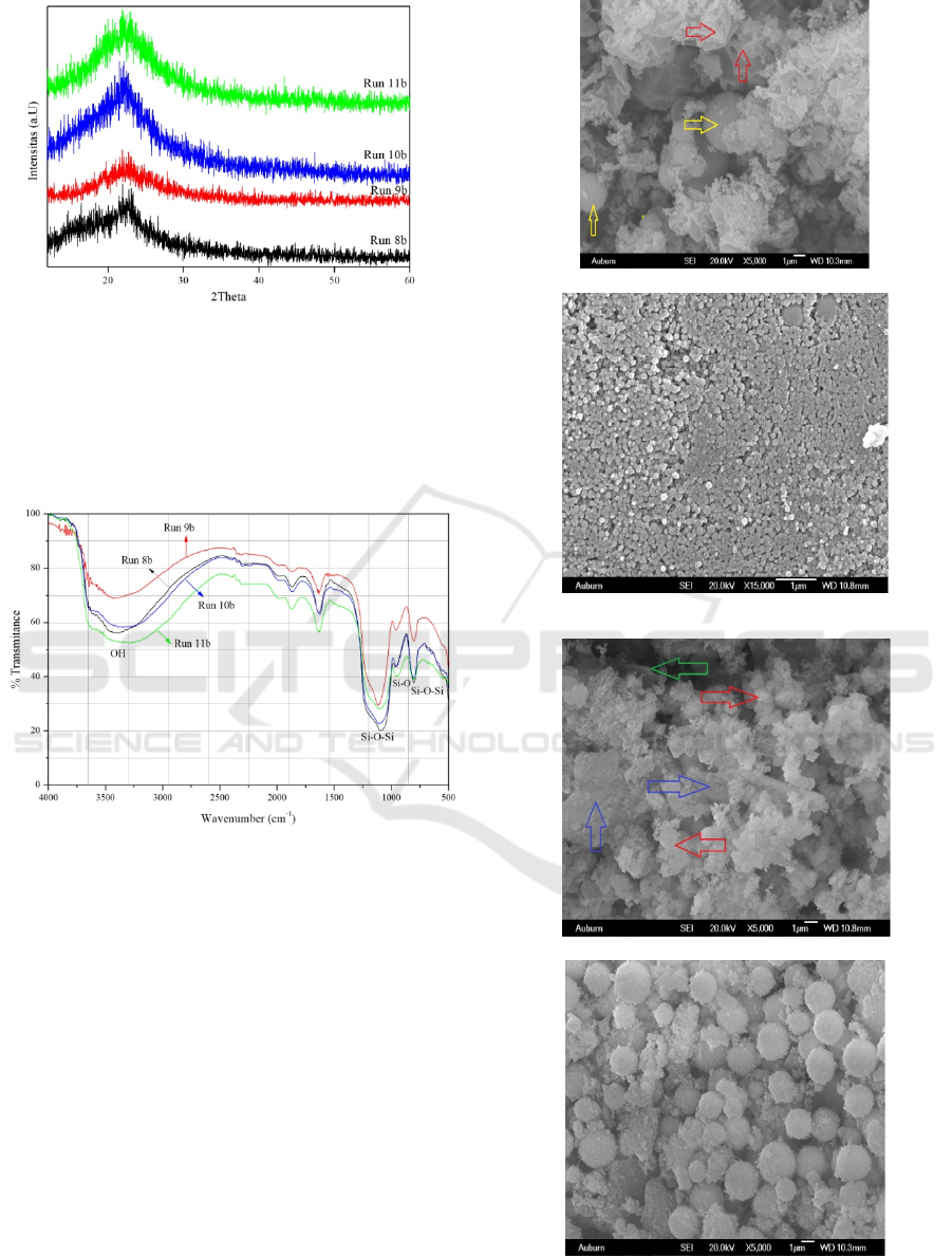
Figure 1: Diffractogram of XRD silica material Run
8b, Run 9b, Run 10b and Run 11b
3.1.2 FT-IR Spectroscopy
FT-IR spectrum of silica material from Run 8b, Run
9b, Run 10b, and Run 11b can be seen in Figure 2
below.
Figure 2: FT-IR spectrum for silica material Run 8b,
Run 9b, Run 10b and Run 11b.
3.1.3 Scanning Electron Microscope (SEM)
Morphological analysis of mesoporous silica material
Run 8b, Run 9b, Run 10b and Run 11b are carried out
with SEM photos with magnifications between
2000X to 25,000X. SEM images are shown in Figure
3 below.
(a) Run 8b (5000X magnification)
(b) Run 9b (15,000X magnification)
(c) Run 10b (5000X magnification)
(d) Run 11b (5000X magnification)
Figure 3: SEM image of silica mesopori material: (a)
Run 8b; (b) Run 9b; (c) Run 10b and (d) Run 11b.
Risinoleaic Acid Derivates as Templates for Synthesis of Mesoporous Silica Material based on tetraethylorthosilicate and
3-aminopropyltrimethoxysilane as Co-structure Directing Agent
1005
SEM image of silica material Run 8b (Figure 3a)
with 5000 times magnification shows the material has
a particle shape in the form of a mixture consisting of
dispersed spherical spherical particles ( sign) and
particles in the form of thin sheets that blend together
to form wrinkled roundabouts and multiples (sign ).
There are also particles that have thin skin / walls that
are susceptible to damage forming sheets (Liu H,
2010)
SEM photo of silica material Run 9b with a
magnification of 15,000 times (Figure 3b) shows
spherical particles of small size having a uniform
shape to form together to form a tight and compact
surface so that there are no gaps between particles. An
increase in the ratio of the amount of methanol added
seems to have an effect on particle size. The particle
size of Run 9b is smaller than the particle size of Run
8b. SEM image of silica material Run 10b with 5000
times magnification (Figure 3c) shows spherically
shaped particles forming an aggregate ( sign) and
also there is a particle shape in the form of large
chunks ( sign) and between particles there is a gap
( sign).
SEM image of silica material Run 11b with 5000
times magnification showing spherical particle shape
that is uniform in shape and dispersed with a more
perfect particle shape. Particle size is greater than
particle size Run 9b and Run 10b.
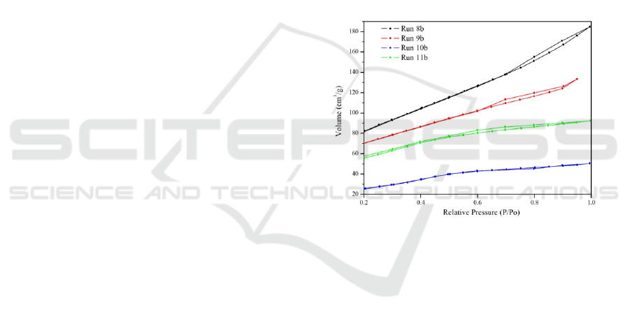
3.1.4 Adsorption-desorption Isotherm
Nitrogen
Porosity analysis of mesoporous silica material and
pore size distribution of Run 8b, Run 9b, Run 10b and
Run 11b were carried out by desorption nitrogen
analysis with isotherm at -196C. The isotherm
adsorption graph was calculated using the Brunauer-
Emmet-Teller (BET) method (Figure 4) and the pore
size distribution was calculated using the Barret-
Joyner-Halenda (BJH) method (Figure 5). Based on
Figure 4, the desorption isotherm adsorption chart
from Run 8b (black graph) shows a graph of
desorption of Type IV adsorption isotherms
according to the IUPAC classification, this is also
adjusted to the literature (Khalil, 2007). The type of
loop hysteresis is caused by the pores in the non-
turbulent aggregate of the particles which results in
slit-shaped pores according to the literature (Shah,
2009). While the desorption adsorption isotherm
graph from Run 9b (red graph) shows Type IV
desorption isotherm adsorption according to the
IUPAC classification is characteristic for mesoporous
material (Khalil, 2007). The existence of a hysteresis
loop is due to the narrow pore gap and includes the
pore of the micropore region, according to the
literature (Shah, 2009). The adsorption isotherm
adsorption graph from Run 10b (blue graph) shows
adsorption of Type IV isotherm according to the
IUPAC classification which is characteristic for
mesoporous material (Khalil, 2007). Pore adsorption
is a type of capillary condensation having a hysteresis
loop which can be caused by channels such as
cylinders or pores formed from coarse homogeneous
spheres forming tight agglomerates according to the
literature (Shah, 2009). Then the adsorption
desorption graph isotherm Run 11b (green graph)
shows adsorption of Type IV isotherm according to
the IUPAC classification which is a characteristic of
mesoporous material (Khalil, 2007). The presence of
a hysteresis loop can be caused by pores formed from
pore channels such as cylinders or pores from coarse
homogeneous sphere particles according to the
literature (Shah, 2009).
Figure 4: Adsorption desorption graph isotherm
nitrogen silica material from Run 8b, Run 9b, Run
10b and Run 11b.
Based on Figure 5, a graph of the pore size
distribution of silica material Run 8b (black graph)
shows a non-uniform pore size distribution in the
range between 1.44 nm to 9.53 nm, this is according
to SEM analysis. Mesopore silica material consists of
mixed particle forms so produced various pore
shapes. The pore size distribution chart of the silica
material Run 9b (red graph) shows that the pore size
distribution is not uniform from 1.43 nm to 9.53 nm.
This is in accordance with SEM photos that show the
form of particles that combine to form a compact and
tight surface. The particle size distribution chart of
silica material Run 10b (blue graph) shows a regular
pore size distribution (uniform) dominated by pore
size at 2.76 nm and 3.07 nm. This is consistent with
SEM photos where dominant particles are spherically
shaped in small sizes. The pore size distribution chart
for silica material Run 11b (green graph) shows a
ICOSTEERR 2018 - International Conference of Science, Technology, Engineering, Environmental and Ramification Researches
1006
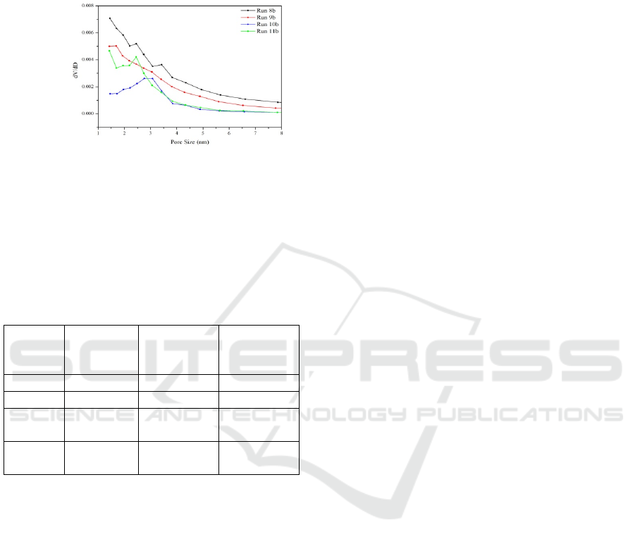
uniform pore size and is dominated by 2.45 nm. This
is consistent with the results of SEM photos showing
the presence of spherical particles that have a uniform
and dispersed size.
Figure 5: Pore size distribution graph of silica
material Run 8b, Run 9b, Run 10b and Run 11b.
Porosity of mesoporous silica material Run 8b,
Run 9b, Run 10b and Run 11b such as diameter and
pore volume and surface area tabulated in Table 2
below.
Table 2: Diameter, pore volume and surface area of
mesoporous material from Run 8b, Run 9b, Run 10b
and Run 11b.
Treatm
ent
Pore
diameter
(nm)
Pore
Volume
(cm
3
/g)
Surface
Area
(m
2
/g)
Run 8b 1.5-9.5 0.02-0.22 54-301
Run 9b 1.4-9.5 0.02-0.16 58-240
Run
10b
3.1 0.04 66
Run
11b
2.5 0.05 113
4 CONCLUSIONS
Synthesis of silica mesoporous material from
tetraethylortosilicate (TEOS) as a source of silica,
sodium risinoleate as template and 3-
aminopropyltrimethoxysilane (APMS) as co-
structure directing agent (CDSA) was carried out.
The results of the FT-IR analysis proved that tissue
was formed (-Si-O-Si-) and the results of XRD
analysis were all amorphous material. The variation
of calming time before the aging stage produces silica
material with different morphology. Porosity analysis
of silica material which has a more uniform pore size
resulted from treatment with time of drying for 2
hours before the aging stage (Run 10b) and the
addition of methanol without the addition of
hydrochloric acid (Run 11b) with a pore size
distribution of 3.1 nm respectively and 2.5 nm.
ACKNOWLEDGMENT
The authors would like to thank to KEMENRISTEK
for the funding on the project of DRPM 2018, number
contract: 231/UN5.2.3.1/PPM/KP-DRPM/2018.
REFERENCES
Schubert U and Husing N 2005 Synthesis of Inorganic
Materials (Wiley-VCH Verlag GmbH & Co, KGoA,
Weinheim) p 308-309
Wan Yand Zhao D 2007 Chemical Rev. 7(107): 2821-2860
Soler-Illia G J et al 2002 Chem. Rev. (102): 4093-4138
Huo Qet al 1994 Nature (368): 317-321
Che S et al 2003 Nature Material (2): 801-805
Garcia-Bennett A E 2005 Angew. Chem. Int. Ed. (44): 5317
–5322
Yokoi T et al 2003 Chem. Mater. 15 (24): 4536-4538
Andriayani et al 2013 Advanced Material Research (789):
124-131
Wang W Q 2009 Journal of Colloid and Interface Science
(331): 156–162
Li B et al 2011 Journal of Colloid and Interface Science
(362): 42-49
Zhao Q et al 2011 Applaid surface Science (257):2436-
2442
Zhang J Z et al 2003 Self-Assembled Nanostructure
(Kluwer Academic Publishers, New York) p
Shah A T et al 2009 Journal of Colloid and Interface
Science (336):707-771
Khali K M S 2007 Journal of Colloid and Interface Science
(315):562-568
Liu H et al 2010 Journal of Colloid and Interface Science
(346):486-493
Park Y et al 2006 Journal of Colloid and Interface Science
(295):464-471
AlOthman Z A and Apblett A W 2010 Applied Surface
Science
(256):573-3580
Zhao Q et al 2011 Applaid surface Science (257): 2436-
2442
Liu H et al 2010 Journal of Colloid and Interface Science
(346):486-493
Khalil K M S 2007 Journal of Colloid and Interface Science
(315):562-568
Shah A T et al 2009 Journal of Colloid and Interface
Science (336):707-771
Gregg S J and Sing K S W 1982 Adsorpsi, Surface Area
and Porosit (Academic Press, Second Edition,
London (LDT) p
Rouqe-Malherbe R M A 2007 Adsorption and Diffusion in
Nanoporous Materia (CRC Press Taylor & Francis
Group) p
Risinoleaic Acid Derivates as Templates for Synthesis of Mesoporous Silica Material based on tetraethylorthosilicate and
3-aminopropyltrimethoxysilane as Co-structure Directing Agent
1007
