
Designing Virtual Practicum Modules for Basic Laboratory of
Telecommunication System
Maksum Pinem*, Muhammad Zulfin, Naemah Mubarakah, Sri Indah Rezkika
Electrical Engineering Department, Universitas Sumatera Utara, Padang Bulan, 20155 Medan, Indonesia
Keywords: Basic Telecommunications, Modeling, Simulation, GUI, Matlab.
Abstract : Accordance with the development of information technology in the form of network technology and software,
then as a companion physical laboratory proposed a powerfull innovation in the form of innovation laboratory
designing and implementing software-based telecommunication system (virtual laboratory).The Virtual
Laboratory presents a number of advantages such as portability, ease of re-deployment processes, to lower
cost of provision and operation.This paper designs and builds a virtual laboratory of telecommunication
systems based on the procurement of virtual individual practical work modules which then integrate between
the modules. Based on the results of the tests conducted, has been obtained and has successfully executed
seven modules of virtual practicum that is integrated and ready to be empowered for student practicum.
1 INTRODUCTION
Procurement of laboratory infrastructure is a part that
often becomes a major obstacle for universities to
produce qualified graduates.One of the challenges
faced by the laboratory is the limitations of physical
practicum modules and measuring instruments.But
there are two solutions offered to overcome the
problem that is by making the device itself as
practicum practiced by (Darlis, A. R, 2013;
Kharisma, W., A., 2013; Supriandani, Y, 2015) the
second solution is to make a breakthrough media
development as a supplement learning teaching
materials lab that so far can be done with two
approaches, namely Augmented Reality or ARLAB
and Virtual Laboratory or commonly referred to as
VLAB. However, the creation of instructional media
should be in accordance with educational standards
and may represent actual practicum (Potkonjak,
2016), so it can be used by learners who have limited
access to laboratory equipment, because basically the
learning media is one model approach to help know,
understand and analyze certain phenomena contained
in a field of science. In addition, one of the principles
of learning media is not limited to use at anytime and
anywhere by anyone who wants to operate.
Virtual laboratory is one form of modern
laboratory that is enough to help institutions,
educators or learners in the implementation of
practice-based learning. The results of a research
survey of students using physical and virtual labs
show that virtual labs are better in terms of physical
security availability (Burd. Stephen D, 2009).
Of course, the development of virtual laboratories
is inseparable from reliable Software support that
integrates computing, visualization and programming
in an easy-to-use environment where problems and
solutions are expressed in familiar mathematical
notation. In the field of engineering, especially
Telecommunication Engineering, the utilization of
GUI-based simulation software such as Matlab which
provides convenience in explaining scientific
concepts when quite a lot of mathematical terms are
involved in the teaching process (Mohamed S. Al
Oraibi, 2016; Shalini Garg, 2014). Therefore, this
research designs and builds a virtual laboratory of
telecommunication systems based on the
procurement of virtual individual practicative
modules which then is done to integrate all the
individual practice modules.
248
Pinem, M., Zulfin, M., Mubarakah, N. and Rezkika, S.
Designing Virtual Practicum Modules for Basic Laboratory of Telecommunication System.
DOI: 10.5220/0010080602480253
In Proceedings of the International Conference of Science, Technology, Engineering, Environmental and Ramification Researches (ICOSTEERR 2018) - Research in Industry 4.0, pages
248-253
ISBN: 978-989-758-449-7
Copyright
c
2020 by SCITEPRESS – Science and Technology Publications, Lda. All rights reserved
2 METHOD
The method used in this study is a simulation method
based on computer programming design with GUI-
based Matlab Software (Averill M. Law, 2000; Math
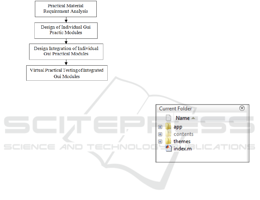
Works., Inc., 2015). The model of the design system
is shown in Figure 1.
Figure 1: Design system model
The steps taken in the design of a virtual
laboratory based telecommunication software system
are as follows:
1. Collecting the need for practicum materials and
literature studies. The seven practical subjects of
the telecommunication system are:
a. Practicum generating oscillator signal by Hartley
method
b. Practicum generation of oscillator signal with
Colpitts method.
c. Practicum of low pass filter characteristics
d. Practicum characteristic of high pass filter
e. Practicum modulator analog amplitude
f. Analog to digital conversion practice (ADC)
g. Digital to analog conversion practice (DAC)
2. Designing individual Practicum Modules
Detailed virtual lab material practicum designed in
Matlab GUI form, RF Oscillator consisting of Colpitt
Oscillator and Oscillator, AM DSB-FC Modulator,
Signal converter consisting of ADC
and DAC signal
converter, and active filter consisting of low pass
filters and high pass filters. The steps in designing the
individual GUI of the entire virtual lab material are
generally outlined as follows:
a. Open the GUI worksheet.
b. Create a figure design using panel components,
slider components, static text, and axes
components into the GUI whose number of needs
is adjusted to each material.
c. Edit the properties of each component by double-
clicking each component then changing its
property as needed. Through property inspector,
each component can be customized starting from
background color, font type, font size, tag and
string.
d. Save a figure by clicking CTRL + S on the
keyboard or by pressing the save button on the
Matlab worksheet.
e. After finished designing the figure, the next step
is to save the figure will automatically be created
m-file frame with the same name.
f. Add a script or program so that the control
components can work.
g. Run the GUI by clicking the runner button on the
tool strip and will produce a view like the saved
image.
3. Designing GUI Module Multitab Integration.
Program Design Multitab GUI Matlab consists of
several files and folders, namely app, contents,
themes, index.m, as shown in Figure 2.
Figure 2: Multitab Folder GUI Matlab
Here is an explanation of the GUI multitab file
and program folder:
1. app, which is a folder that contains a set sintax
m-file that serves to arrange the entire tab in the
integrated GUI.
2. contents, that is, the folders containing the
individual GUI sets that will be displayed on the
integrated GUI tabs.
3. themes, namely the folder containing the theme
to change the display theme of multitab GUI
application.
4. index, the m-file that serves to call the app to run
multitab GUI application Matlab.
The first thing the program does is get the directory
names in the contents directory. There all the contents
of the tabs you want to display in the main GUI are
stored. The code for obtaining the names of the
existing directories is CONTENTS =
Designing Virtual Practicum Modules for Basic Laboratory of Telecommunication System
249
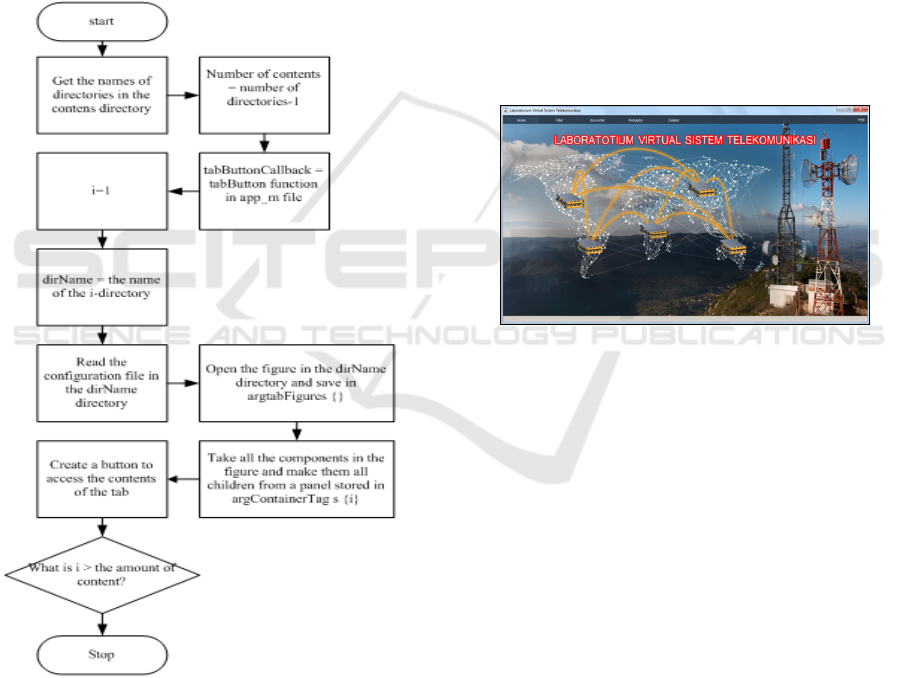
DIR(ARG.CONTENTSDIR). Then the number of
existing directories is stored inside the contentCount
variable. This number is subtracted by two because
the directory directory "." And the directory ".."
which is the navigation directory are also counted.
Then from the directory names obtained looping
operations to open the file figures in each directory
and retrieve data from the figure and move it to the
main GUI data. A button will then be created on the
main GUI to access this figure data from the main
GUI. As long as each loop of the configuration file in
each directory is also read and applied to the tab in
question. The existing configuration is the tab key
title that will be displayed on the main GUI as well as
the name of the documentation for the tab in question.
Figure 3: Flowchart Main GUI Reading Process
For a clearer picture, the process of reading each
figure of a directory into tabs in the main GUI can be
seen in the flowchart in Figure 3.
To add a tab from the contents folder, by creating
a new GUI project or using an existing GUI project,
save the project in the [PROJECT_NAME] folder
with the naming [PROJECT_NAME] _contentview,
so after the save two files will be obtained:
[PROJECT_NAME] _contentview.fig and
[PROJECT_NAME] _contentview.m. If using an
existing project, save as project with the file name in
accordance with the same provisions. Then create the
"config.txt" file in the "contents /
[PROJECT_NAME]" folder, then save it and exit it.
To remove or reduce unwanted GUIs, simply delete
the previously created project folder.
3 RESULT AND DISCUSSION
To run the Integrated GUI Virtual Lab is as follows:
a. In the GUI mutitab program folder, click "index"
twice. Then click the runner button, or
b. In the GUI mutitab program folder, type "index"
in the command window, so it will show at
Figure 4.
Figure 4: Multitab Main GUI Display
3.1 Testing of RF Oscillator GUI
The steps to run the RF Oscillator GUI are as follows:
1. In the integrated GUI, select or click the
"oscillator" tab, then it will be directed to the
overview tab page.
2. Select the "RF Oscillator" tab. GUI
Oscillator RF which consists of Hartley
Osilator and Colpitt Oscillator.
3.1.1 Hartley Oscillator
The steps to run it are as follows:
1. Set the value of L1 and L2 to determine the value
of inductor 1 and inductor 2
2. Set the C value to determine the value of the
capacitor
3. Set the value of A to determine the signal
amplitude value, so it will produce as in Figure
5.
ICOSTEERR 2018 - International Conference of Science, Technology, Engineering, Environmental and Ramification Researches
250
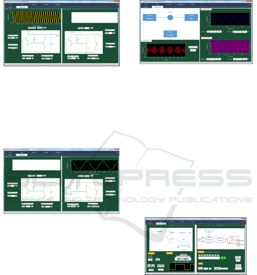
Figure 5: Test Result of GUI Oscillator Hartley
3.1.2 Colpitt Oscillator
The steps to run it are as follows:
1. Set the value of C1and C2 to determine the value
of inductor 1 and inductor 2
2. Set the value L to determine the value of the
capacitor
3. Set the value A to determine the signal amplitude
value, so it will produce a display like Figure 6.
Figure 6: Test Result of GUI Oscillator
3.2 Testing of AM Modulator GUI
The step to run it are as follow:
1. In the integerated GUI, select or click the
“modulator” tab, then it will be
2. Select the “AM Modulator”
3. Set the amplitude value of the information signal
4. Set the frequency value of the information signal
5. Set the amplitude value of the carrier signal
6. Set the carrier signal frequency value
7. Set the modulation index value
Figure 7 shows the test results obtained with a
maximum frequency of 5 Hz information signal
input, the input signal information amplitude of 0.3
V, the carrier signal input frequency is 30 Hz, the
amplitude of the input signal 0.2 V with the
modulation index 1.
Figure 7: Test Result GUI AM Modulator
3.3 Testing of Signal Converter GUI
The steps to run GUI Converter Signals are as
follows:
1. In the integrated GUI, select or click the
“converter” tab, then it will be directed to the
overview page.
2. Select the “AD & DA Converter” tab. This AD
& DA Converter Tab consists of GUI Converter
of ADC and DAC signals merged into one tab.
3.3.1 DC Signal Converter
Converter A / D or ADC converts analog
measurements from 0.00 V up to 5.00 V into digital
measurements with 8-bit resolution. Figure 8 shows
the conversion result of analog voltage 1.115 V. Then
obtained the quantization value 1.12125. From the
quantization value then obtained the code number 57
and converted into binary form to 0011 1001 and
shows the pulse form in NRZ format.
Figure 8: Test Result of GUI Converter Signal
3.3.2 DAC Signal Converter
In Figure 9 we can see the example of D / A signal
Converter testing. The digital or binary input is
11001011 .This value is then converted to a decimal
number to obtain the code number 203 .From the
value of the number code then obtained the
quantization value of 3.9682.Of the previous values
then obtained value for the analog output current of
0.8435 A and an output voltage analog of 3.9648 V.
Designing Virtual Practicum Modules for Basic Laboratory of Telecommunication System
251
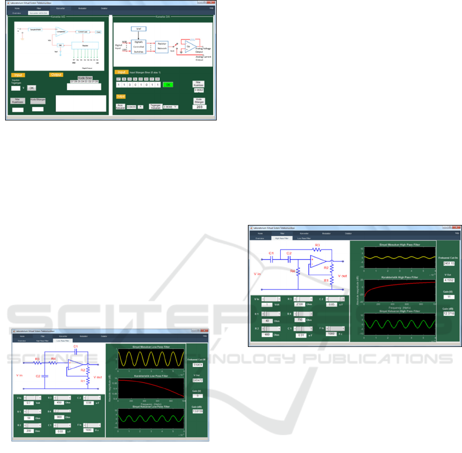
Figure 9: Result of GUI DAC Signal Converter
3.4 GUI Testing Active Filter Low Pass
Second Order
The steps to run the Active Pass Second Order Low
Pass GUI are as follows:
1. In the integrated GUI, select or click the " filter "
tab , then it will be directed to the overview page
2. Select the "Low Pass Filter" tab
3. Set Vin value set at 0.7 V, R1 50 Ohm, R2 200
Ohm, R3 450 Ohm, R4 900 Ohm, C1 0.03 μF,
C2 0.08 μF, and Fin 1000 Hz , then the result are
obtained, ie the cut-off frequency of 5104.9 Hz,
V out at 3.43472 V dan Gain (dB) at 13.8159 dB,
so it will display the results in Figure 10.
Figure 10: Test Result of Low Pass Active Filter
3.5 GUI Testing High Pass Active
Filter Second Order
The steps for running the Second Order High Pass
Active GUI Filter are as follows:
1. In the integrated GUI, select or click the "filter"
tab, then it will be directed to the overview
page.
2. Select the "High Pass Filter" tab
3. Set Vin value to determine input voltage value
4. Set the value of R1 to determine the value of
resistance 1
5. Set the value of R2 to determine the value of
resistance 2
6. Set the value of R3 to determine the value of
resistance 3
7. Set the value of R4 to determine the value of
resistance 4
8. Set the value of C1 to determine the value of
capacitor 1
9. Set the value of C2 to determine the value of
capacitor 2
10. Set the F
in
value to specify the input frequency
value.
By adjusting V
in
1 V, R1 40 Ohm, R2 400 Ohm, R3
2100 Ohm, R4 750 Ohm, C1 0,31 μF, C2 0,85 μF,
and F
in
1000 Hz. Results obtained, ie cut-off
frequency of 2451.15 Hz, V
out
of 4.1552 V and Gain
(dB) of 12.3718 dB obtained from the logarithm of
the ratio between V
out
and V
in
. Test results can be
seen in Figure 11.
Figure 11: Result of High Pass Active Filter
4 CONCLUSIONS
Based on the results of the tests conducted, has been
obtained and has successfully executed seven
modules of virtual practicum that is integrated and
ready to be empowered for student practicum. The
innovative design and implementation activities of
the laboratory. The software - based
telecommunication system has supported a collegiate
strategy plan to prepare a superior learning system
that empowers information technology systems and
builds recognition and reputation.
ACKNOWLEDGMENT
The work of this research is supported by DRPM
kemenristekdikti of applied research scheme for
budget year 2018. No. :192/UN5.2.3.1./PPM/KP-
DPRM/2018.
ICOSTEERR 2018 - International Conference of Science, Technology, Engineering, Environmental and Ramification Researches
252

REFERENCES
Averill M. Law & W. David Kelton. (2000). Simulation
Modeling & Analysis. Third edition, ISBN 13:
9780070366985, McGraw – Hill International.
Burd. Stephen D, et al. (2009). Virtual Computing
Laboratories: A Case Study with Comparisons to
Physical Computing Laboratories. Journal of
Information Technology Education: Innovations in
Practice.
Darlis, A. R., Trisapto, P., Jambola, L. (2013). Design and
Realization of Short Message Transmisian System and
Digital Signal on BATM Modem based on MATLAB.
Itenas Engineering Journal. 17(1): pp, 1-12.
Kharisma, W., A., Utama, J. (2013). Portable Digital
Oscilloscope Based on PIC18F4550. Telekontran,
1(2): 39-49
Math Works, Inc. (2015). Matlab Creating Graphical
User Interface, The MathWorks, Inc.3 Apple Hill
Drive Natick, MA 01760-2098.
Mohamed S. Al Oraibi, M. R. Qader. (2016). Teaching
Frequency Modulation To Undergraduate Electrical
And Electronics Engineering Students Using
Matlab/Simulink. Journal of Advance Research in
electrical Electronics & Communication Engineering.
Potkonjak, Veljko, et al. (2016). Virtual laboratories for
education in science, technology, and engineering: A
review. ELSEVIER Computers & Education. 95: pp,
309-327
Shalini Garg and Pragati Kapoor. (2014). Design &
Development of Graphical User Interface (GUI) for
Communication Link with PSK Modulation using
Adaptive Equalization.
Supriandani, Y., Budiawan, I., Ekawati, E. (2015). Design
and Implementation of Digital Sound Oscilloscopes.
Proceedings of the National Seminar on
Instrumentation, Control and Automation (SNIKO).
pp, 167-173.
Designing Virtual Practicum Modules for Basic Laboratory of Telecommunication System
253
