
System Modeling and Design Exploration of Applications
for Heterogeneous and Parallel Platforms
Alessandra Bagnato
1
, Etienne Brosse
1
, Alexandre Beaufays
1
,
Andrey Sadovykh
1
, Pascal Faure
2
, Simone Casale-Brunet
3
, Endri Bezati
3
,
Marco Mattavelli
3
, Matthieu Pfeiffer
4
, and Emmanuel Vaumorin
4
1
Softeam Research & Development, 21 avenue Victor Hugo, 75016 Paris, France
{alessandra.bagnato,etienne.brosse}@softeam.fr
2
AKAtech SA, ch de Champs Courbes 21, 1024 Ecublens, Switzerland
{p.faure}@akatech.ch
3
EPFL SCI STI MM, Station 11, 1015 Lausanne, Switzerland
{simone.casalebrunet,endri.bezati,
marco.mattavelli}@epfl.ch
4
Magillem Design Services, 251 rue du Faubourg Saint Martin, 75010 Paris, France
{pfeiffer,vaumorin}@magillem.com
Abstract. This article presents an overview of the context and outcomes of the
Eurostars MODELS project. The project is developing an unified environment
for the design of system applications on parallel platforms based on CPU, multi-
core, manycore, FPGA and heterogeneous SoCs. The design tools composing
this environment provides an unified SW/HW specification interface and system-
atic procedures for composing models at different abstraction levels allowing for
the automatic validation, drastically reducing the verification and debugging ef-
forts.
Keywords: System modeling · Design exploration
Heterogeneous and parallel platforms
1 Introduction
The implementation of processing demanding applications can be satisfied by using
new multi/many-core processing platforms, but new designs or porting IPs on them is
difficult and costly. The integrated design flow of this project intends to provide: port-
ability of IPs, systematic system design explorations, high level synthesis of executa-
bles, systematic test-bench generation at different design abstraction levels. All means
to achieve cost effectiveness of designs on parallel platforms.
The pivotal technical product of this project is a design/development environment
consisting of a suite of software tools and associated artifacts (libraries, applications,
documentation etc.). It supports a platform-independent programming model geared
toward streaming application areas such as signal processing, video compression, dig-
70
Bagnato, A., Brosse, E., Beaufays, A., Sadovykh, A., Faure, P., Brunet, S., Bezati, E., Mattavelli, M., Pfeiffer, M. and Vaumorin, E.
System Modeling and Design Exploration of Applications for Heterogeneous and Parallel Platforms - System modeling Â˚u Design exploration Â˚u Heterogeneous and parallel platforms.
DOI: 10.5220/0008862100700090
In OPPORTUNITIES AND CHALLENGES for European Projects (EPS Portugal 2017/2018 2017), pages 70-90
ISBN: 978-989-758-361-2
Copyright
c
2019 by SCITEPRESS – Science and Technology Publications, Lda. All rights reserved

ital modulation, industrial visual inspection, 3D medical image processing, data pro-
cessing, audio processing and many others, and their efficient implementation on a wide
range of commercial parallel platforms, from SMP multicores, to manycores, processor
arrays, programmable logic devices, and heterogeneous SoCs. The essential features of
the approach are: high level platform independent system specification, design space
exploration capabilities, automatic synthesis of executables, automated verification and
validation of designs at different abstraction levels. Another particular concern in this
context is a principled approach to leveraging legacy IP, i.e. the use of existing code
and optimized platform-specific modules in the development process. A key role of the
industrial project partners was to provide important specific requirements and contexts
that influenced the development of the software tools, and then to apply, customize,
and re-target them to their respective platforms and applications, adding to the project
result.
The main project result is the set of SW tools and libraries supporting portable sys-
tem design on many- and multi-core heterogeneous platforms building a step forward
beyond sequential programming approaches.
The goal of MODELS consists in creating a viable high-level parallel programming
framework that targets as wide a range of parallel processing substrates as possible and
is aimed at stream-processing applications. In order to do this, the project builds on
existing infrastructure and tools, and incrementally adds to and improves on them.
The main improvements over prior art can be summarized as follows:
- Holistic approach to system design in the form of a complete design flow starting
from specifications down to implementations. This will enable developers to take into
account functional and non-functional issues across all layers relevant to the design,
and across all implementation targets.
- High-level parallel programming of a diverse range of platforms, from small embed-
ded devices to high-performance computing environment using an extension of the
RVC-CAL dataflow language. This allows designers to defer system-level decisions
such as those on partitioning and mapping parts of an application to the various pro-
cessing elements in an architecture until late in the design process.
- A unified tool infrastructure based on a formal machine model which allows applica-
tions to be partitioned and implemented flexibly across target architectures, and also
includes a complete range of programming tools (debugger, profiling, analysis, ...) that
help programmers to investigate, optimize, refactor and transform complete applica-
tions irrespective of partitioning and implementation choices, and to gradually inject
implementation decisions and change them easily in order to efficiently explore a wide
range of design alternatives.
- Sophisticated profiling and analysis capabilities that account for the structure of the
computation as well as its quantitative aspects, and that goes beyond processing time
to also include analysis of power consumption, memory use, as well as communication
bandwidth and latency.
- Integration of data encryption at the tool level for increased security with minimal
trouble to the designer.
- Extensive automatic design verification powered by the dataflow model of computa-
tion
71
System Modeling and Design Exploration of Applications for Heterogeneous and Parallel Platforms - System modeling Â˚u Design
exploration Â˚u Heterogeneous and parallel platforms
71

Although existing design frameworks (including, on one hand, those based on OpenCL,
OpenMP and MPI, and, on the other hand, today available HLS tools such as Vivado,
CatapultC and so on) realize some of the individual features of the list above, no exist-
ing development environment comes even close to covering all of them, including
many that are mandatory for next-generation programming paradigm for low-power
parallel computing platforms.
The project was initially motivated by the observation of the state of the art:
- System level tools: a large number of projects advocate the usage of MDD, but they
do not provide a methodology that takes into account aspects related to RTES system
specification, design space exploration, IP-reuse, code generation and the implementa-
tion on platforms. Moreover, they do not focus on early stage design exploration.
- Programming languages: the limitations of sequential code has led manufacturers of
silicon devices to build programming tools geared toward their specific platform. An
early example is Occam promoted by Inmos for programming their Transputers. More
recent examples include Ambric's aJava in support of their Am2045, and Nvidia's
CUDA targeting their GPUs. While library-based approaches naturally allow users to
write programs in familiar languages, they require them to code to the specifics of a
particular platform, making portability impossible.
- Customized general-purpose languages and environments: some manufacturers of
parallel silicon build on existing languages/environments to support their products (e.g.
Adapteva provides an environment built on Eclipse that allows their processor array to
be programmed in C, using a special backend)
- Parallelizing compilers: there have been a number of attempts at building compilers
that automatically parallelize sequential programs. Fortran and C have a rich history of
compilers trying to extract program's concurrency, with some successes only for rela-
tively regular loop constructs. More recently, tools have appeared that attempt to trans-
late subsets of sequential languages(C or C++) into circuits, usually targeting program-
mable logic devices.
In summary, none of the existing design flows and tools vendors provide the portability
and HW/SW composability that this project is developing.
1.1 Business Context for the Project
The consortium has been composed to cover the value chain of computing system de-
sign from tools integrators (Softeam, Magillem), to application providers including sys-
tem integrator and use-case provider (AKAtech) In particular, Softeam and Magillem
are major player in tools for model-based design. This consortium has also a strong
background in standardization activities. Recommendations to standards bodies are di-
rectly supported by member companies in MODEL who are active members of Analy-
sis & Design Task Force (ADTF) of the Object Management Group (Softeam is a plat-
form member of OMG and is contributing to the newly developed MARTE and SysML
MODELS advances to the portfolio of ADTF) and ISO/IEC MPEG standardization
committee (EPFL is the leader of the efforts for advanced system level specification
efforts).
72
EPS Portugal 2017/2018 2017 - OPPORTUNITIES AND CHALLENGES for European Projects
72

AKAtech will benefit from the increased productivity resulting from adopting a
high-level approach and the tools developed in this project when applied to his respec-
tive application areas. The consequent portability and flexibility along with the dramat-
ically increased re-use will allow to significantly reduce the non-recurring engineering
in their development, and might also create new opportunities such as portable IPs. The
system modeling layer, Design Space Exploration and optimization tools developed
within the project will be sold to companies developing high performance embedded
stream processing systems on parallel processing platforms. An appropriate end user
license agreement (EULA) will be issued for the tools themselves, as well as associated
artifacts (board support packages, specialized libraries, platform-specific tools), distri-
bution is planned to happen via the usual channels (online, physical media).
1.2 Project Results
The development tools created in this project support fluid portability and scalability
of application code across heterogeneous mix of implementation targets. The resulting
degree of flexibility and re-use offered to programmers is without precedent and can
thus legitimately be considered a new product. In contrast with existing tools on the
market, including high level synthesis tools – such as Vivado HLS, the IDE of the pro-
ject will enable programmers to develop applications without the need to partition and
map them onto processing elements until the end of the implementation phase. IPs de-
veloped with these tools also will constitute a new class of product creating a new mar-
ket of retargetable parallel software.
The proposed development builds on a solid core of existing technologies of various
levels of maturity, some of them entirely or in part developed by the project partners.
One part of the technical work in the project consisted of integrating these technologies
into a coherent whole, guided by the experience of the industrial partners, and by the
expectations and requirements of their respective clients. Another focus is on improv-
ing even further the performance of the implementation results by adding new optimi-
zations to the synthesis stages as well as increased system design exploration capabili-
ties and libraries for a wide platform support. Building on the excellent results demon-
strated on certain classes of applications and platforms in the past, a wider range of
implementation targets and application areas is supported, thus achieving a true porta-
bility of IPs and system design on parallel and heterogeneous platforms, feature that is
extremely limited and require extensive costly SW rewriting phases if based on the
traditional sequential low level approaches.
2 Details of the IDE
The IDE developed in the project is composed of different tools useful through all
phases of a design of a new system. A coarse grain view of the IDE is depicted on
Figure 1:
73
System Modeling and Design Exploration of Applications for Heterogeneous and Parallel Platforms - System modeling Â˚u Design
exploration Â˚u Heterogeneous and parallel platforms
73
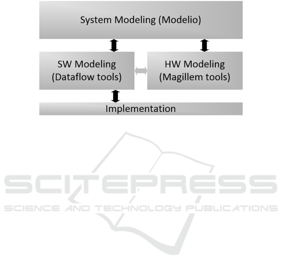
Fig. 1. Coarse grain view of the IDE.
The system tools are useful during the specifications phases and allow system designers
for modeling a complex system at high-level. Modelio integrates these system tools and
is presented in the next section. In the context of the project, Modelio automates the
early stages of the development since it is able to synthesize the structure of the models
for Hardware and Software Modeling. These models can then be refined by using the
respective tools, Magillem tools for HW modeling, and Dataflow tools for SW model-
ing (Orcc/Exelixi, Tÿcho and Turnus). The HW modeling tools allows designers for
modeling the hardware platform under development, while the SW modeling tools al-
low software designer for implementing the application that will be targeted on the
platform. The system tools are able to import back the HW and SW models to keep
traces of the changes or to define a mapping of the subsets of the application on the
processing elements of the hardware platform. When this mapping is defined at system
level, it can be transmitted to the dataflow tools for design space exploration purpose
or for synthesis purpose.
3 System Modeling Tools - Modelio
3.1 Modelio Tool
The system modeling environment of the project is built on top of the modeling tool
named Modelio (https://www.modelio.org/). Modelio is an open source modeling tool
which supports, among other, UML, BPMN2, SysML, and MARTE standards.
Modelio Architecture is based on an Eclipse Rich Client Platform and a central repos-
itory that can be extended for different purposes and is available with a set of predefined
extensions.
74
EPS Portugal 2017/2018 2017 - OPPORTUNITIES AND CHALLENGES for European Projects
74
Each extension provides some specific facilities, which can be classified in the follow-
ing categories:
Scoping: this category is composed of Goals, Dictionary & Business Rules
and Requirement Analyst which allow specifying high-level business models
for any IT system;
Modelling: for example, SysML, MARTE and BPMN are included in this cat-
egory. The extensions belonging to this category are used to model different
specific aspects of a system such as Business Process, component architec-
tures, SOA or embedded systems;
Code generators: such as C++ or JAVA. These extensions allow users to gen-
erate and to reverse the code to/from different programming languages;
Utilities: modules allowing transversal utility facilities like teamwork or Im-
port/export functionalities.
These extensions enrich Modelio graphical interface, shown on Figure 2, by defining
new views or diagrams, adding specific commands or interactions, or masking non
needed concepts.
Fig. 2. Overview of Modelio tools interface.
3.2 MODELS Modelling Methodology
During the specifications phases, system engineers have to model the high-level
(coarse-grain) architecture of the design under development. This is done by using both
Block Definition Diagram (SysML BDD) and Internal Block Diagram (SysML IBD)
to specify the different Blocks, Ports and Interfaces composing the system. Rather than
specifying the whole system in details, designers have to sketch the system by defining
the main Blocks/Components, describing their goals/functionalities and specifying the
interfaces and connections between them. The idea here is to separate the different
75
System Modeling and Design Exploration of Applications for Heterogeneous and Parallel Platforms - System modeling Â˚u Design
exploration Â˚u Heterogeneous and parallel platforms
75

components (possible future software or hardware components) and their responsibili-
ties inside the system definition. An example of such model is illustrated on Figure 3,
which corresponds to a Parking Assistance System.
Fig. 3. Modelio – Parking Assistance System – High Level Model.
More information about SysML can be found at http://www.omgsysml.org/ and the
Modelio implementation is available at http://forge.modelio.org/projects/sysml
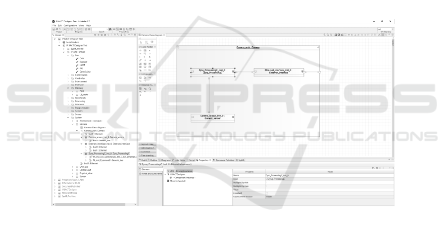
Starting from this High-Level model, a skeleton of the hardware architecture can be
extracted, generated as an IPXACT model and visualized in Modelio IPXACTdesigner
tool. This model can then be refined by Hardware designers by using Magilem tools as
described in section 4.
In terms of specifications of functionalities, an UML design has to be elaborated.
This is done at system level by using Modelio. From this additional model, a skeleton
of the software application can then be synthesized (networks of dataflow model) in
order to be refined by software designers by using dataflow tools as detailed in section
5.
More information concerning system modeling in the context of MODELS project
can be found at: http://forge.modelio.org/projects/eurostarsmodels
76
EPS Portugal 2017/2018 2017 - OPPORTUNITIES AND CHALLENGES for European Projects
76
4 HW Modeling Tools
4.1 Detailed HW Modeling in IP-XACT
The Magillem tools suite contains a variety of tools modules dedicated to HW platforms
and leveraging the IP-XACT (IEEE1685) standard. The IP-XACT standard consists in
a digital specification of HW components and platforms, enabling to represent all the
HW-related characteristics in a tool-agnostic manner e.g. components, ports, intercon-
nections, hierarchy, registers and memory map.
Hence, the corresponding IP-XACT models is a golden reference of all information
related to hardware, that can be leveraged for tasks included in engineering activities
such as specification, design, documentation, as well as integration of HW/SW systems.
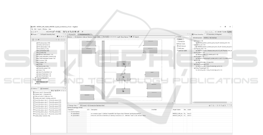
4.2 Detailed HW Modeling Tools
The Magillem tools suite is composed by various modules enabling to capture IP ad
platform description in IP-XACT, handle hierarchy and interconnections between com-
ponents, verify design rules, check consistency of the resulting HW models, and man-
age configurability of the platform.
Fig. 4. Overview of Magillem tools interface.
In the MODELS environment, Magillem Platform Assembly (MPA) is the backbone
of detailed HW modeling. MPA is a powerful and intuitive Integrated Design Environ-
ment to guide HW designers when configuring and assembling their platforms. MPA
also helps streamline the exploration and the implementation of IP-based systems.
MPA supports both top-down and bottom-up modeling approaches and includes
scripting mechanisms and generators to simplify the modeling of complex platforms,
e.g. manycore platforms or processor arrays with hundreds of processing elements.
77
System Modeling and Design Exploration of Applications for Heterogeneous and Parallel Platforms - System modeling Â˚u Design
exploration Â˚u Heterogeneous and parallel platforms
77
In the context of MODELS, the objective is to extract information out of the detailed
platform models and provide a subset of dimensioning information towards system
level in order to guide the partitioning and allocation choices to find the best trade-offs
for the considered application.
Regarding hardware, this consists in providing information related to the kind of
processing elements, their characteristics and performances, information about the to-
pology of the platform and characteristics of the potential data paths between them (in-
terconnection, protocols, bandwidth).
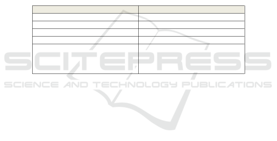
4.3 Relation to the HW Architectural Modeling Tools
In the MODELS environment, the allocation modeling is performed at system level and
hence leverages SysML for representing SW and HW components. The abstract repre-
sentation of HW components is based on SysML Internal Block Diagram, enabling to
describe hierarchical structure of components and whose concepts can be mapped to
IP-XACT in the following way:
SysML IBD
IP-XACT
Diagram
Component & Design
Instance
Component Instance
Port
WirePort & BusInterface
Parameter & Constraint
Attribute
Connector
AdHocConnection
Exported AdHocConnection
HierConnection
InterConnection
Fig. 5. Correspondence of SysML and IP-XACT modeling concepts.
4.4 Documentation Publisher
The MODELS environment includes a publishing framework, enabling to generate var-
ious types of documentation out of design items and then manage the traceability be-
tween design and documentation elements at fine granularity, throughout the design
phases.
Indeed, documentation is required and incurred by the different design activities,
involving different types of documents, each one containing information dedicated to a
view of the designed system or of its components e.g. datasheet, test plan, user guide,
specification. These documents are intrinsically linked and at the same time necessarily
evolve concurrently throughout the system design phases.
Maintaining consistency of the system documentation as a whole is a tedious task, as
one piece of information in one documentation item can have adherence on various
sections of several other documents. The usual way to ensure the consistency of the
documentation with the actual implementation of the system is by performing reviews,
for a specific release of the system and associated documentation at a given point in
78
EPS Portugal 2017/2018 2017 - OPPORTUNITIES AND CHALLENGES for European Projects
78
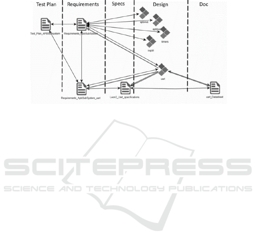
Fig. 6. Documentation over design phases.
time. However, these reviews are particularly time consuming and costly, while they
do not guarantee consistency during the design phase, but only a posteriori.
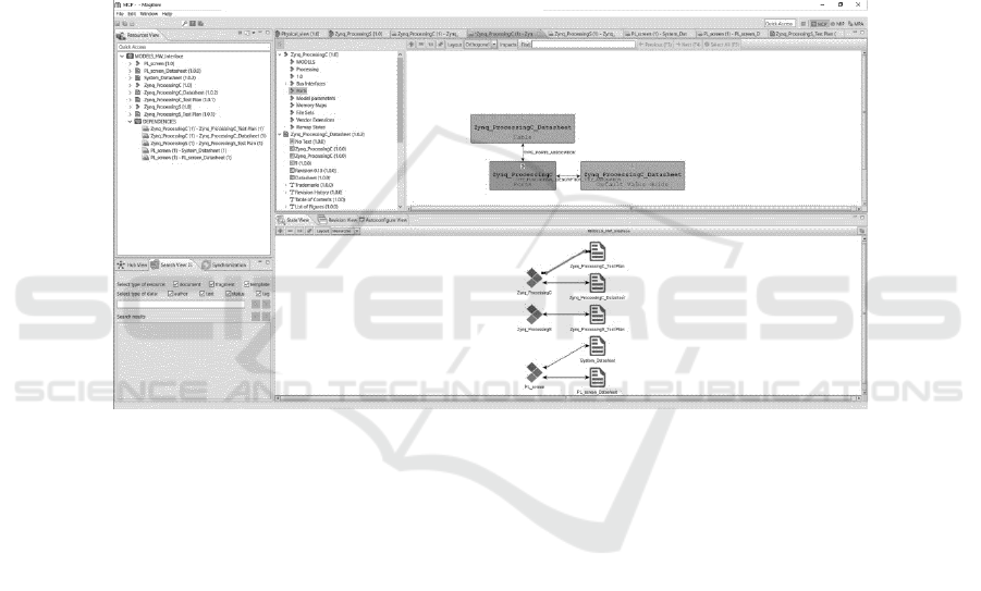
4.5 Consistency of Documentation throughout System Design Phases
The objective of the MODELS publisher is to manage semantic-rich links between the
design items and their associated documentation, and ensure consistency across design
and documentation over the flow. To achieve this goal, the idea is to consider each
design or documentation item as a structured assembly of fragments, and then create
and handle links between information fragments, which are defined by:
A direction (uni- or bi-directional): The direction enables to specify the infor-
mation flow and the way data shall be propagated.
The relationship between fragments: The nature of relationship is expressed
by a semantic information, describing the way that fragments are intercon-
nected. This semantic relation shall be associated with generators, in order to
automate the propagation and consolidation of an updates information to its
linked fragments, and maintain consistency between them.
The methodology and associated publishing framework are supported by the Magillem
Content Publisher (MCP). It covers the various process steps described in section 4.6.
4.6 Methodological Steps
1) Import: The first step consists in importing the design and documentation items in
the referential. Dedicated connectors identify the information fragments composing
these items.
2) Link: The second step consists in creating the network of semantic links between the
fragments. They can either be created automatically – by identifying and implementing
business rules – or manually in the tool.
79
System Modeling and Design Exploration of Applications for Heterogeneous and Parallel Platforms - System modeling Â˚u Design
exploration Â˚u Heterogeneous and parallel platforms
79
3) Update: Once one documentation or design item is updated, the tool computes a
differential analysis of the item, in order to identify the contained information frag-
ments that have evolved.
4) Analyze: Then a change impact analysis is launched, leveraging the semantic links
network, in order to identify the linked information fragments that are potentially im-
pacted and propose to the user the corresponding consolidation actions to be performed.
5) Consolidation: Based on the change impact analysis report generated in the previous
step and on its own expertise, the user can approve or reject the consolidation actions
proposed. If a generator has been defined for the semantic link, the consolidation shall
be performed automatically. Else the list of consolidation action is generated as a report.
Fig. 7. Magillem Content Publisher interface.
5 SW Modeling Tools
The software modeling tools used and developed in the project rely on the dataflow
approach since it offers the following properties:
Explicit Concurrency & Parallelism Scalability
o Expresses an application as network of processes
o Explicit concurrency of the Actor Model
o Actor Composition Mechanism
Modularity
o Hierarchical Structure
o Changing an Actor does not have an impact on other Actors
Portability
o Single representation for HW and SW components
o Maintainability and reuse of the code
80
EPS Portugal 2017/2018 2017 - OPPORTUNITIES AND CHALLENGES for European Projects
80
The dataflow model of computation is introduce in the following section, and the data-
flow tools are presented in the next one.
5.1 Dataflow Model
A dataflow model of computation (MoC), is conceptually represented as a directed
graph where nodes, called actors, represent computational units, while edges describes
communication channels on which tokens are flowing. A token is an atomic piece of
data. Dataflow graphs are often used to represent data-dominated systems, like signal
processing applications. Using Dataflow MoC in such application domains often leads
to behavioral descriptions that are much closer to the original conception of the algo-
rithms than if an imperative MoC was used. Dataflow models also date back to the early
1970s, starting with seminal work by Dennis and Kahn. Several execution models that
define the behavior of a dataflow program have been introduced in literature. A Data-
flow MoC may constrain the behavior of an actor, how actors are executed relatively
to each other, and aspects of their interaction with one another. As a result, different
MoCs offer different degrees of analyzability and compile-time schedulability of data-
flow programs written in them, and permit different guarantees (such as absence of
deadlocks or boundedness of buffers) to be inferred from them.
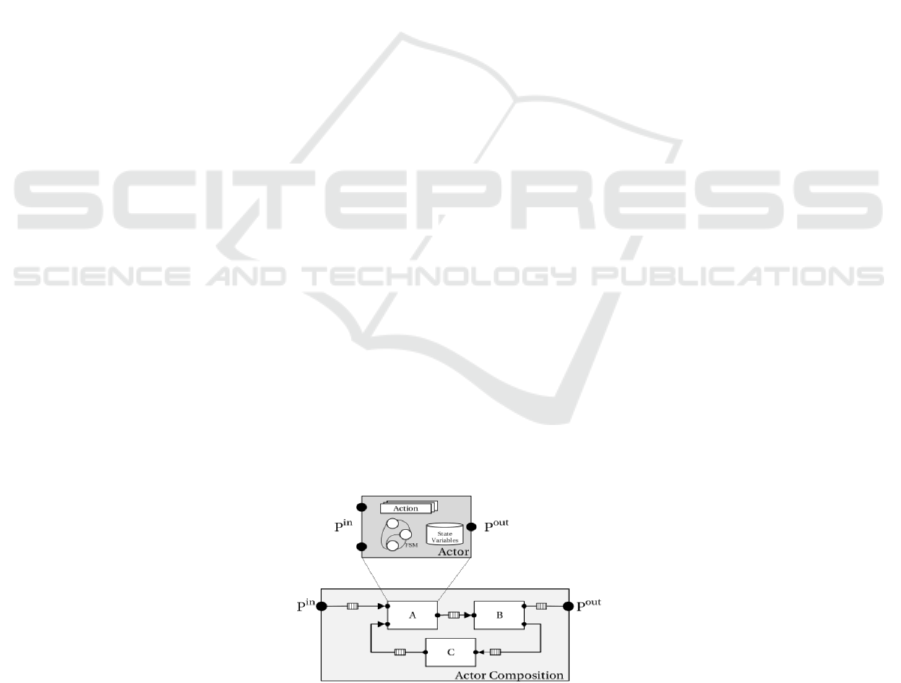
The dataflow modeling tools used and expanded during the MODELS project offers
an integrated environment using the CAL programming language as a formal descrip-
tion language for developing dataflow applications. CAL is dataflow programming lan-
guage that permits to express a wide range of different dataflow models. The basic
concepts of a CAL program are presented on Figure 8. It represents a simplistic data-
flow network composed by a set of actors and a set of first-in first-out (FIFO) queues.
Each CAL actor is defined by a set of input ports, a set of output ports, a set of actions,
and a set of internal variables. CAL also includes the possibility of defining an explicit
finite state machine (FSM). This FSM captures the actor state’s behavior and drives the
action selection according to its particular state, to the presence of input tokens, and to
the value of the tokens evaluated by other language operators called guard functions.
Each action may capture only a part of the firing rule of the actor together with the part
of the firing function that pertains to the input/state combinations enabled by that partial
rule defined by the FSM. An action is enabled according to its input patterns and guards
expressions. While patterns are determined by the amount of data that is required for
the input sequences, guards are boolean expressions on the current state and/or on input
sequences that need to be satisfied for enabling the execution of an action.
Fig. 8. Dataflow Model.
81
System Modeling and Design Exploration of Applications for Heterogeneous and Parallel Platforms - System modeling Â˚u Design
exploration Â˚u Heterogeneous and parallel platforms
81
5.2 Dataflow Environment
The dataflow environment is based on Orcc/Exelixi (http://orcc.sourceforge.net/),
Tÿcho(https://bitbucket.org/dataflow/dataflow) and Turnus(https://github.com/turnus),
an open-source integrated environment based on Eclipse and dedicated to dataflow pro-
gramming. It has been developed with the contribution of several of the partners in-
volved in MODELS project. It offers to developers a compiler infrastructure and asso-
ciated tools for designing streaming applications. All the tools are integrated in Eclipse
as a set of plugins and provide interfaces to users with standard elements: Visual data-
flow graph editing, Assisted writing of actors, Simulating and Debugging. Furthermore,
the environment includes tools providing guidelines to designers for optimizing their
implementations. Rather than directly synthesizing assembly code or executable for
CPU or bitstream for FPGA, different synthesizers are available for generating source
code that can be used as input for standard compilers (Gcc, Visual studio, Catapult,
Vivado and so on). Thus, the environment should be considered as a front-end of stand-
ard tools commonly used by developers.
Visual Graph Editing
Creating a new design from scratch is extremely intuitive since few mouse clicks are
sufficient to build a network, and few more allow designers to assign to the node a
refinement: network or actor. When assigning an existing actor (or network), all ports
are visible in the visual interface, allowing designers to add edges to create communi-
cation path (tokens) from one node to another (or to an input/output of the network). In
the context of the Models project, the structure of the dataflow application can be syn-
thesized from the System tools (Modelio) and refinements have to be done with the
dataflow tools.
As an example, a dataflow model as the one presented on Figure 9 can be created in
few minutes:
Fig. 9. Dataflow Environment – Simple dataflow application.
82
EPS Portugal 2017/2018 2017 - OPPORTUNITIES AND CHALLENGES for European Projects
82
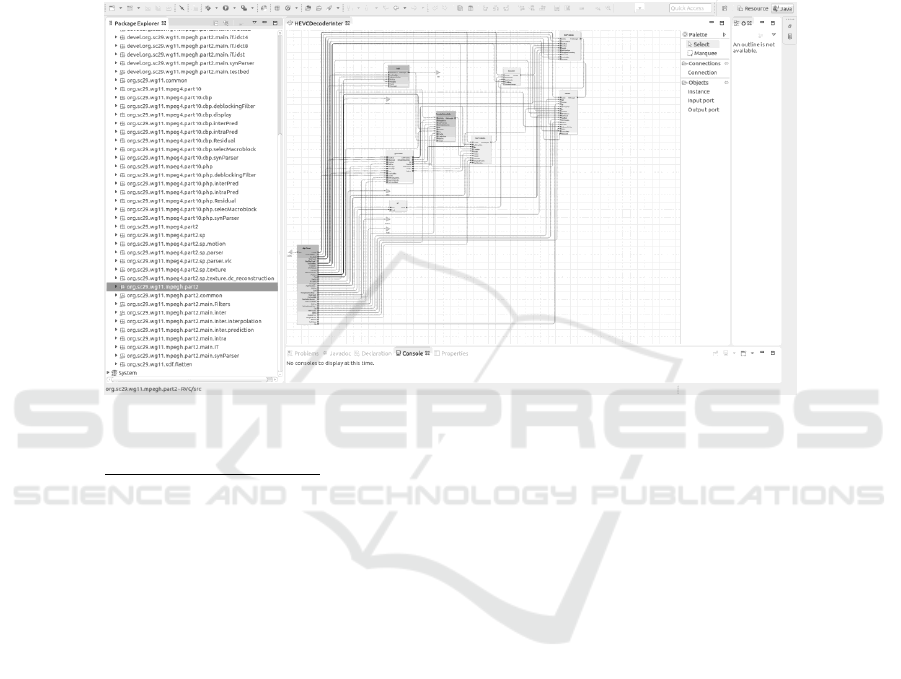
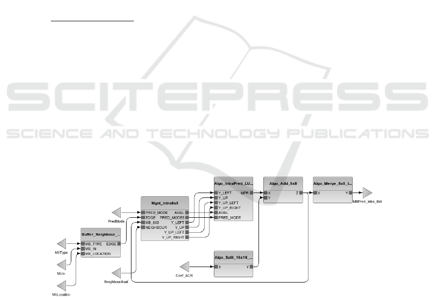
More complex designs are available among the different examples coming with the
tools, such as the design depicted on Fig 10 which corresponds to the top view of a
Mpeg Hevc decoder implemented in dataflow. Several nodes of this graph are hierar-
chical and refer to sub-graphs that implement underling data processing. The main
nodes of this network are: the Parser, the Intra-prediction, the Inter-Prediction, the In-
verse Transform, the Filters and the Decoded Picture Buffer.
Fig. 10. Dataflow Environment – HEVC decoder.
Assisted Writing of Actors
The editor for writing dataflow actors in CAL language implements all the features
expected for a modern editor, such as auto-completion, on the fly validation and so on.
Moreover, the editor is parsing actors on the fly to build their intermediate representa-
tion incrementally, allowing fast simulation and compilation.
The following snippet of dataflow source code corresponds to the implementation of
one actor of the Inter-prediction previously presented:
package org.sc29.wg11.mpegh.part2.main.inter.interpolation;
import std.util.Math.* ;
actor MulChromaRow ()
uint(size=3) XFrac,
uint(size=8) A,
uint(size=8) B,
uint(size=8) C,
uint(size=8) D
83
System Modeling and Design Exploration of Applications for Heterogeneous and Parallel Platforms - System modeling Â˚u Design
exploration Â˚u Heterogeneous and parallel platforms
83

==>
int(size=16) AO,
int(size=16) BO,
int(size=16) CO,
int(size=16) DO
:
interpolate.go.bypass: action XFrac:[xFrac], A:[ a ], B:[ b ], C:[ c ], D:[
d ]
==> AO:[0], BO:[b], CO:[0], DO:[ 0 ]
guard xFrac = 0
end
interpolate.go.filter0: action XFrac:[xFrac], A:[ a ], B:[ b ], C:[ c ],
D:[ d ]
==> AO:[2*a], BO:[58*b], CO:[10*c], DO:[2*d]
guard xFrac = 1 or xFrac = 7
end
interpolate.go.filter1: action XFrac:[xFrac], A:[ a ], B:[ b ], C:[ c ],
D:[ d ]
==> AO:[4*a], BO:[54*b], CO:[16*c], DO:[2*d]
guard xFrac = 2 or xFrac = 6
end
interpolate.go.filter2: action XFrac:[xFrac], A:[ a ], B:[ b ], C:[ c ],
D:[ d ]
==> AO:[6*a], BO:[46*b], CO:[28*c], DO:[4*d]
guard xFrac = 3 or xFrac = 5
end
interpolate.go.filter3: action XFrac:[xFrac], A:[ a ], B:[ b ], C:[ c ],
D:[ d ]
==> AO:[4*a], BO:[36*b], CO:[36*c], DO:[4*d]
guard xFrac = 4
end
end
Simulation and Debug
The environment includes two innovative tools for simulating and debugging dataflow
programs.
Concerning simulation, a Java based simulator allows developers to quickly validate
their implementation in terms on functionality and without taking in consideration spe-
cific details from the targeted hardware platform. This simulator interprets the internal
84
EPS Portugal 2017/2018 2017 - OPPORTUNITIES AND CHALLENGES for European Projects
84
intermediate representation of networks and actors and can virtually interact with ex-
ternal devices such as camera and display via models implemented with native actors.
Concerning debugging, the simulator is used to build an execution trace keeping dif-
ferent details of the states of the actors and the fifos interconnecting them. In terms of
features, the designers can monitor specific states or values of variables in the complex
situation of parallel debugging. Moreover, the tool is maintaining a backtrace of the
execution allowing designers to discover the reason of a bug or deadlock that may arise.
Synthesis for Different Processing Elements
As stated in the previous sections, the environment is providing a large set of compilers
allowing to synthesize source code such as C, C++, HDL and so on. The main innova-
tion compare to the tools available on the market is that the same dataflow implemen-
tation of an application can be synthesized for different hardware platforms, such as
single core CPU, multi-core CPU, many-core CPU, FPGA and any combination of
them. The codesign tool provides also the ability of integrating interconnections be-
tween processing elements based on libraries coming as Board Support Packages with
the dataflow environment. Thus, the environment offers tools that allows designers for
targeting a large set of heterogeneous parallel hardware system.
5.3 Design Space Exploration
The heterogeneity of modern parallel architectures and the diverse requirements of tar-
get applications greatly complicate modern systems design. Developing efficient appli-
cations for this kind of platforms requires design methodologies that can deal with sys-
tem complexity and flexibility. In this context, the systematic exploration of the design
space, which is less significant for sequential processors, becomes an essential step
when porting applications to heterogeneous and parallel platforms. This is due to the
combinatorial explosion of design options when dealing with multiple concurrent pro-
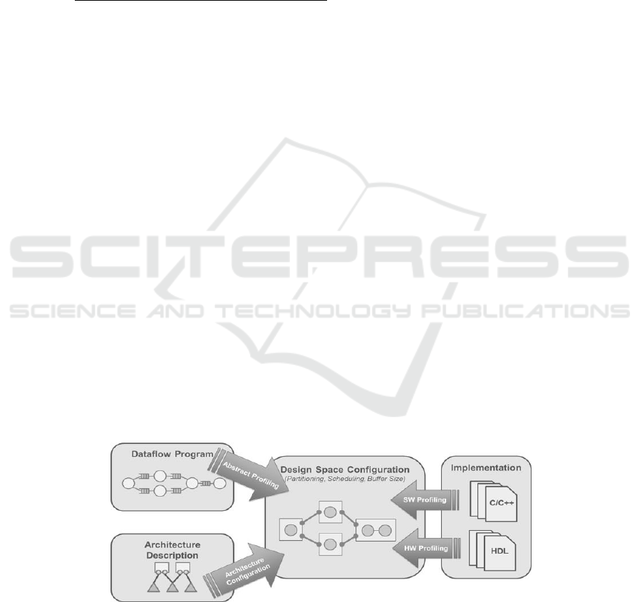
cessing units. The design space exploration tools of the project (TURNUS) can be used
by engineers for helping them in refining their models and speeding up the process of
taking decisions. Indeed, TURNUS offers various levels of abstraction for estimating
the performance of dataflow applications. Figure 11 is presenting an overview of some
levels of abstraction.
Fig. 11. TURNUS – Design Space Exploration – Abstraction levels overview.
85
System Modeling and Design Exploration of Applications for Heterogeneous and Parallel Platforms - System modeling Â˚u Design
exploration Â˚u Heterogeneous and parallel platforms
85
The very first step of design space exploration is a functional (i.e. high-level and plat-
form-independent) profiled simulation. During this stage, an exhaustive analysis of the
design under study is performed leading to the definition of its basic structure and com-
plexity. This initial analysis enables multidimensional design spaces explorations and
helps in finding bottlenecks and potentially unexploited parallelism. TURNUS imple-
ments a dataflow profiler based on the simulator presented in the previous section and
adds profiling information on top of the interpreter of the IR: for each executed action
both (a) the computational load and (b) the data-transfers and storage load are evalu-
ated. The computational load is measured in terms of executed operators and control
statements (i.e. comparison, logical, arithmetic and data movement instructions). The
data-transfers and storage load are evaluated in terms of state variables utilization, in-
put/output port utilization, buffers utilization and tokens production/consumption.
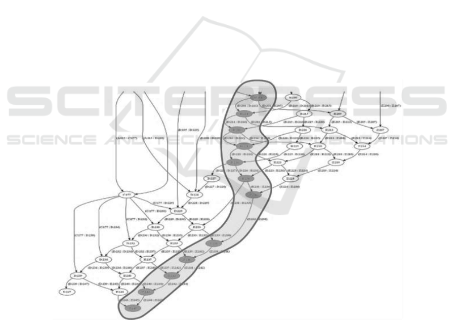
Moreover, it is possible to extract the execution trace for each run of the simulation.
The execution trace is a multi-directed graph that stores all the dependencies be-
tween actions of a design and fully describes the program behavior. For dynamic appli-
cations, such as Mpeg H265, where dependencies of firings vary with input stimulus,
TURNUS is able to store several execution traces and offers probabilistic results which
are meaningful if the input stimulus are sufficiently large with respect to the type of
application. The execution trace is stored in the DSE suite as a Graph Markup Language
(GraphML) formatted file allowing for reusing it during different co-exploration stages
without requiring further simulation runs. An example of Execution Trace is shown on
Figure 12.
Fig. 12. TURNUS – Design Space Exploration – Partial Execution Trace.
86
EPS Portugal 2017/2018 2017 - OPPORTUNITIES AND CHALLENGES for European Projects
86
Among the different functionalities of TURNUS, it is possible to post process the
Execution Trace in order to estimate the performance of the application for a given
configuration (partitioning of application on HW platform). This is particularly useful
for HW designers for evaluating different HW alternatives such as communication
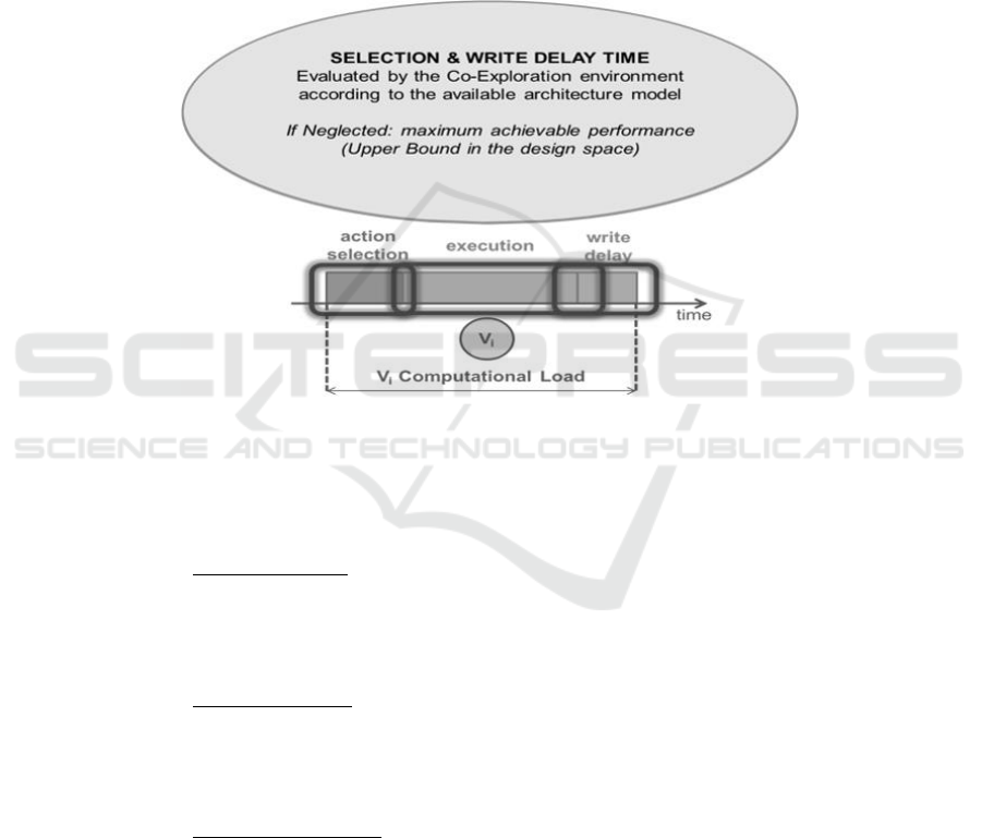
paths, memory size, type of processing elements. To this end, a weight is assigned to
each fired action of the Execution Trace which is defined as the computational load.
However, the total computational load of an action consists in the sum of the overhead
introduced by the action selection (scheduler), the execution time itself (on the pro-
cessing element) and the overhead introduced by the read/write delay (reading of FIFOs
from actors producers of tokens and writing to the FIFOs for actors consumers).
Fig. 13. TURNUS – Design Space Exploration – Action Computational load.
By using the Execution Trace and the weighted computational load, TURNUS is able
to provide efficiency metrics that can drive the optimization effort of developers when
the performances requirements are not met:
Code Complexity: Highlights the portion of code that require much effort to
be executed, like standard profiler, such as Valgrind, GnuProf,, and even for
subsets of code that is mapped on FPGA. Moreover, Actors, Actor classes and
Actions are ranked by their code complexity
Critical Path (CP): Determines the longest sequential path of an application
and allow for detecting the design bottlenecks (i.e. for improving the final
throughput). This is allowing for detecting the most critical Actors and Actions
and the most critical Buffers (only for bounded buffer configuration analysis)
Impact Analysis (IA): Defines the most critical action as the action that re-
quires the less refactoring effort in order to maximally reduce the CP. This is
shown on Figure 14.
87
System Modeling and Design Exploration of Applications for Heterogeneous and Parallel Platforms - System modeling Â˚u Design
exploration Â˚u Heterogeneous and parallel platforms
87
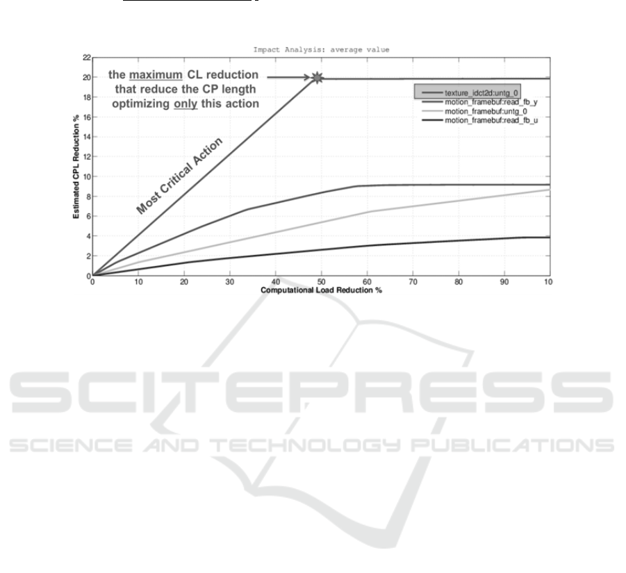
Logical Zeroing (LGZ): Highlights the set of actions that requires the minimal
refactoring effort in order to maximally reduce the CP. It must be noted that
some of this actions can be not initially critical
Fig. 14. TURNUS – Impact analysis on MPEG4.
6 Mapping Details
Mapping subsets of an application on a target hardware platform is usually either done
according to the experience of designer, according to functionalities logical location or
a mix or them. Indeed, the hardware is usually designed by keeping in mind where will
be allocated the code and memory and other resources are chosen accordingly. How-
ever, even if evolutions were planned, it may become extremely difficult to anticipate
how will evolve the application in its life, and in many cases the hardware is largely
oversized to comply with such constrain. In the case of parallel and heterogeneous sys-
tems, it is even more difficult to find how to distribute the code on the different pro-
cessing elements composing the system.
In order to speed up the process of selecting which subset of an application should
be allocated on which processing element, the design space exploration tools presented
in the previous section is offering solutions based on heuristics. These heuristics are
based on the different constrains specified by the user (resource usage minimization,
power consumption, throughput…).
In the context of the project, it has been defined that the mapping should be specified
at system level, since it is the main location where designers can have a global view of
the entire system. Modelio provides both interfaces for visualizing HW models
(IPXACTdesigner) and SW models (CALdesigner). Moreover, it provides a specific
tool to allocate the SW elements to the HW elements. On Figure 15, an example of
mapping of a simple application composed of three actors on a hardware platform com-
posed of two ARM processor is shown.
88
EPS Portugal 2017/2018 2017 - OPPORTUNITIES AND CHALLENGES for European Projects
88
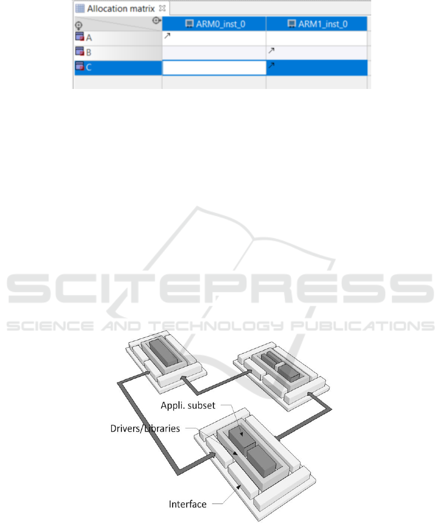
Fig. 15. Modelio - Allocation – simple example.
It is nothing to say the allocation tool is able to support large and hierarchical models
of applications and hardware. An interesting feature is also available to map the edges
of a network on physical interfaces where, for instance, not only the physical layer can
be chosen, but also the protocol and the policy of scheduling the packets of token to
transmit and receive.
When the mapping is specified, the tool allows for exporting it under the form of an
XML file which is supported by the dataflow tools for synthesis of for design space
exploration purpose. This is highly suitable for testing different configurations without
having to manually implement a new code (or hardware).
On Figure 16, a more sophisticated platform is presented.It is composed of one board
based on a FPGA, connected to two other, for instance via respectively Ethernet and
PCIexpress, the second board is a Zynq based heteogerneous SoC, while the third one
is based on a dual-core (standard PC, Intel I5).
In this case, the dataflow tools, based on the libraries (and Borad support Packages),
can synthesize the source code in C/C++ and HDL of the application according to the
chosen mapping. Moreover, as it is depicted on the Figure, the drivers and libraries are
included to the generated projects (composed of makefile, static/dynamic libraries and
scripts, for instance for Vivado/VivadoHLS).
Fig. 16. Distributed HW architecture.
89
System Modeling and Design Exploration of Applications for Heterogeneous and Parallel Platforms - System modeling Â˚u Design
exploration Â˚u Heterogeneous and parallel platforms
89

7 More Information
This article presented different aspects of the MODELS project and the Integrated De-
sign Environment which has been developed. More details can be obtained by contact-
ing one of the partners of the project:
AKAtech, SWITZERLAND (PME), coordinator: p.faure@akatech.ch
EPFL, SWITZERLAND (University): marco.mattavelli@epfl.ch
ULUND, SWEDEN (University): Jorn.Janneck@cs.lth.se
SOFTEAM, FRANCE (ETI): alessandra.bagnato@softeam.fr
Magillem Design Sevices, FRANCE (PME): pfeiffer@magillem.com
The book chapter describes the MODELS project as it has been presented during the
European Project Space Workshot within MODELSWARD 2018 in Madeira.
Acknowledgments. The research presented in this book chapter is funded by the
EUREKA EUROSTARS Project MODELS (MEASURE, Measuring Software Engi-
neering) started on 1st September 2016 and running till 31st March 2019.
90
EPS Portugal 2017/2018 2017 - OPPORTUNITIES AND CHALLENGES for European Projects
90
