
Supercapacitors Serving as Power Supply in Tiny Sport Sensors
Field Testing Through Heart Rate Monitoring in Endurance Trail Runs
Hans Weghorn
BW Cooperative State University, Kronenstrasse 53A, 70174 Stuttgart, Germany
Keywords: Body Sensor, Heart Rate Monitor, Endurance Training, ANT+, Bluetooth LE.
Abstract: In professional and in non-elite sport activities, people today are using various electronic monitoring tools
quite commonly. Sportspersons often are embedded into a personal body sensor network, which traces
different parameters of their physiological activity. Especially heart rate sensors are used broadly, but often
all kinds of meters, e.g., for counting foot steps and pedal turning, are also utilized in parallel. As technical
construction, it has commonly established that these sensor devices are autonomously operated as very tiny
computer systems from built-in lithium battery cells. Replacing such sensor batteries from time to time is
expensive, the mechanical handling of this process is not very easy due to the small sensor housings, and it
has to be reminded that use of throwaway batteries represents a waste of resources. In this work, an
alternative power supply for sports sensors is investigated, which bases on the use of so-called
supercapacitors. Construction concepts, advantages of the approach related to handling and manufacturing,
and the possible application ranges are thoroughly discussed, while the study is complemented with
practical experiments from endurance running sports.
1 INTRODUCTION
Improving health by controlled physical activities
plays an important role in our modern and aging
societies. Performing personal sports on regular and
moderate base from early living days represents a
valuable key for preserving an extended period with
fewer health problems already at middle age
(Oguma and Shinoda-Tagawa, 2004) up to higher
ages (Jefferis et al, 2014). Both categories of
physiological activities are today usually monitored
with the help of electronic devices and tools for
achieving optimal response (Arts and Kuipers,
1994). The simplest variants of such monitoring
units are pedometers or smartphones with
corresponding software tools (Tudor-Locke and
Basset, 2004).
A higher or more professional elaboration level
is achieved, when sports computers with built-in or
RF-linked sensors are employed (Malkinson, 2009).
One of the most well-known samples of this multi-
device monitoring are chest straps with an
autonomous sensor module for detecting heart beats
from skin surface electrodes and producing
continuously measures of the heart rate (HR), which
are sent to other control units for display, evaluation
and recording. Fig. 1 shows three different HR
devices, two of them communicate through the so-
called Bluetooth LE standard (Bluetooth SIG, 2017),
while the third unit (device S) broadcasts its
measures through ANT+ radio (Dynastream Innov.
Inc., 2011). The latter can be received by many
sports computer systems and by some smartphones
with special RF electronics, while Bluetooth LE is
readable by most modern smartphones. It has been
reported earlier (Weghorn, 2015) that the electrical
power consumption of the ANT+ system is lower
compared to the Bluetooth LE solution.
Similar sensors exist for different other
physiological measures, which are likely to be
observed and traced during sports and health
exercises. For instance, tread rate in foot stepping,
wheel and pedal turning rate in cycling and other
information may be of relevance and interest in such
applications. Accordingly, many sensor types are
available on the market and a training person can be
embedded into an extended wireless body network,
which consists of one central control unit and
several autonomous sensor elements.
Since such sensors are constructed as tiny
wireless computer modules, they do require also an
electrical power supply. For this, commercial
Weghorn H.
Supercapacitors Serving as Power Supply in Tiny Sport Sensors - Field Testing Through Heart Rate Monitoring in Endurance Trail Runs.
DOI: 10.5220/0006515100560065
In Proceedings of the 5th International Congress on Sport Sciences Research and Technology Support (icSPORTS 2017), pages 56-65
ISBN: 978-989-758-269-1
Copyright
c
2017 by SCITEPRESS – Science and Technology Publications, Lda. All rights reserved
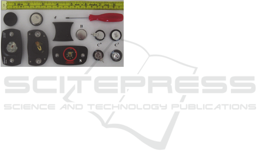
devices use lithium battery cells (B in Fig. 1), which
have to be replaced and disposed as hazardous
waste, when they are emptied. This manual
exchange is not very easy, because the mechanical
parts are tiny and some systems need considerable
force and torque for opening and closing the battery
mould covers. Fig. 1 shows above each sensor its
back case part for the battery cell; for sensor S very
small screws have to be handled, which is already
inconvenient and complicate for younger people and
may render impossible for older people or health
patients with reduced sensitivity. Another negative
aspect of inconvenience is, that these batteries are
rather expensive.
Figure 1: In here at bottom left, three different heart rate
sensors are visible from backside. Above each sensor, its
cover for the supply battery is shown, the middle one has
to be fixed with four tiny screws. On bottom right, rear
and top view of supercapacitors samples are sown, which
are possibly feasible for replacing the lithium sensor
batteries.
In the tiny sensor devices rechargeable batteries
like in wristbands are not in use, because such a
technology would increase size and price of the
systems. Furthermore, wrong maintenance like deep
discharge for a longer while damages accumulators
and make the entire unit worthless, because the
accumulator usually cannot be exchanged.
Coin-type accumulators are available in the same
housing like the batteries, but with ten times lower
capacity, what means the manual exchange for
recharging would be required even ten times more
often. Derived from commerce of simple time
watches, development has concentrated therefore on
reducing power consumption of the sensor devices.
The energy load of a single-use battery cells allows a
continuous operation of the sensors for few days, but
in real practical use cases this long operational time
is not really required for physical exercises. In
medical investigation, in health and sports
monitoring, workouts and exercises quite typically
last in the order of one hour (USD Labor, 2009).
Using switching capacitors as power cell
theoretically provides much better convenience for
electronics design than batteries, but this was not
possible since the electro-chemical capacitors with
sufficient energy storage amount haven't been
available for long time. Around two decades ago, so-
called supercapacitors, which are also named
ultracapacitors, could be developed on base of
upcoming nanotechnology (Conway, 1999) and
since then, capacitor parts caught up to the desirable
high storage of one Farad and more. Today after
many years of further evolvement, supercapacitor
(SC) application is well-known in sports, e.g., as
power supply for boosting temporarily Formula 1
race cars as term of an ultra high power and extreme
current cell (Lu, 2013).
Another recent application field for SCs is the
replacement of backup batteries for configuration
memory on computer boards (SC samples are C
x
and
C
y
in Fig. 1). This scenario is very similar to what is
required for operating sport sensors, since they need
also a high capacity value, which is sustaining very
long time a rather small electrical current. Out of the
four fundamental SC types, this variant represents a
prospective candidate for replacing the throw-away
lithium battery cell in autonomous sports sensors
with a self-sustaining electronic part.
Inspired from this existing knowledge and the
new technologies, the work here discusses first the
general properties of modern supercapacitors with
respect to the targeted application frame in sports
sensing; next the substitution idea particularly is
used for the most common sensor of HR detection in
endurance training for a real-world evaluation of the
approach. Following this, the derived findings and
possible concepts for further applications and
improvements are critically reflected in their
relevant details.
2 PROPERTIES OF FEASIBLE
SUPERCAPACITORS
From practical experience through a longer period of
on-going investigation about handheld sports tools
and sensors, it had been estimated as initial working
base, that a SC part in the order of one Farad should
provide sufficient energy for at least one or even few
hours of sport sensor operation. This estimate bases
on the practical experience, that a 230 mAh lithium
battery can be used approximately one week full
week (Weghorn, 2015). The error bar of this
assumption is rather high, because controversially
the advertisements and promotion material for the
sensors and their technologies promise much longer
operational times. Due to the small voltages and the
very small supply current it is not possible to
measure the sensor energy consumption directly
with high precision, especially not during longer
physical workouts. Therefore, an indirect
methodology was applied in the further investigation
for the determination of a sufficient power supply
capacity.
2.1 Initial Parts Selection and
Laboratory Setup
At first, two different supercapacitor types had been
selected from a quality manufacturer for passive
electronic parts, which are matching the targeted use
of low voltage combined with low current. Other
important criteria were also, that these parts are
available from stock and that the size of the parts is
comparable to the size of lithium battery cells. Part
C
x
is specified as SC with 5.5 Volts maximum and a
capacity of 1.5 F, while C
y
- despite it has got a
bigger housing - comes with the same voltage rating
and 1.0 F. For the evaluation of statistical variation
in specified ratings and parameters, sample sets were
purchased from professional suppliers for electronic
parts. The data sheets specify for the storage
capacity possible differences from -20% up to
+80%, but this wide range is expected to emerge
reduced, since the body sensors are used in a much
narrower temperature band than allowed in the total
specification ratings.
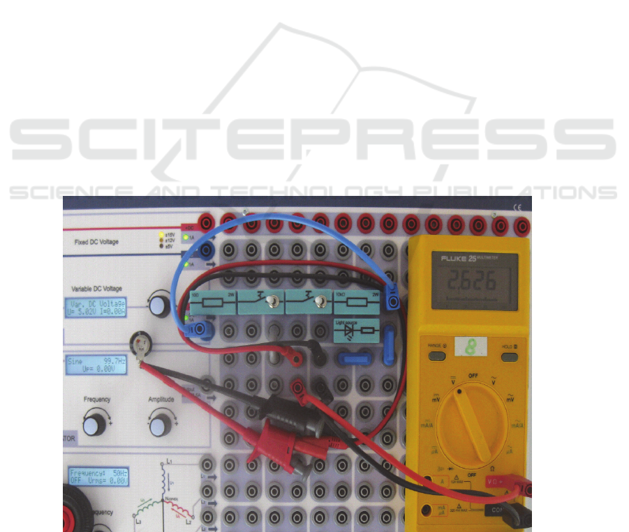
Fig. 2 shows the laboratory board setup for
conducting the basic experiments. The circuit allows
to charge the SC probe through a protection shunt at
a defined voltage and to discharge it through a
defined load. The load in the test circuit was
dimensioned, so that the discharge from 5V down to
3V takes in the order of one hour, since this should
be similar like to the minimal estimated working
time of a health or sports sensor. This test circuit
maps to the following replacement construction for
the battery cell: a linear voltage regulator
downscales the SC voltage band to the valid sensor
supply voltage, which lies between 2.7V and 3.3V as
yielded by lithium battery cells during their life
span.
2.2 Determining SC Storage Capacity
For each of the two different SC parts C
x
and C
y
five
samples were tested with the laboratory setup in a
charge/discharge cycle. In this first experimental run
the variation in capacity should compared be under
conditions similar to the use inside a sport sensor.
Table 1 shows the corresponding results, and it
indicates that the experienced variation of the
capacity between different part samples is much
lower than specified in the data sheets.
Figure 2: Laboratory board for charging and discharging the supercapacitor probe. A digital voltmeter measures
precisely the probe output.

Although the discharging is non-linear according
to the fundamental rules, this can not explain high
difference between the discharging slope within the
defined voltage steps completely. The reason more
is, that supercapacitors behave in some aspects
considerably different to electrolytic capacitors,
since they do stand only low switching frequencies
and their internal resistance increases with charging
load. As observed in the experiments, it is not
sufficient to connect SC for a short while to the
desired charging voltage, following the definition of
how to measure SC capacity, it would even more be
required to keep the target charging voltage up for
half an hour. Since this is not realistic for the
intended application frame here, charging was
terminated after an acceptable time for a sports user.
The consequence is, that the discharge rate is over-
proportional high in the first phase as seen in the
middle row in Table 1, because the SCs were not
charged completely.
Table 1: Discharging time results for the ten SC samples:
each probe was charged up to 5.00V, then this load
voltage was sustained for a further minute, after which the
discharging was initiated. From there, the time delay was
measured in seconds for a voltage drop of each probe
down to 4.00V and then further down to 3.00V.
SC probe
t for
5.00V 4.00V
t for
4.00V 3.00V
x
C
1
534s 1155s
x
C
2
555s 1164s
x
C
3
490s 1117s
x
C
4
491s 1123s
x
C
5
478s 1105s
y
A
C
456s 880s
y
B
C
422s 854s
y
C
C
457s 865s
y
D
C
422s 876s
y
E
C
394s 856s
Next, two reference measurements of the
absolute capacity had been performed for SC type
C
x
and C
y
. For obtaining precise values, the SC
probes were charged in the beginning to a higher
voltage for an increased waiting time.
Following this, the slope of the discharge curve
was measured at a lower voltage frame, i.e. after the
over-proportionally fast discharge phase. In addition,
a plain resistive load was used. Table 2 shows all
experimental parameters and the deduced results.
The determined reference capacities are much lower
than the specified values from the data sheets.
Table 2: Experiment of determining the absolute capacity
value for reference.
item/event mode
x
C
3
y
C
C
V
SC
(t
0
=0) defined&set 5.00V 5.00V
R
L
= 10k
selected
measured
resistance R
L
9.93kΩ 9.93kΩ
@V
SC
(t
1
)
= 4.50V
measured
time t
1
05:16:05 08:44:22
@V
SC
(t
2
)
= 4.00V
measured
time t
2
05:35:40 09:01:08
t
2
- t
1
calculated 1175s 1006s
C calculated 1.00 Farad 0.86 Farad
From these reference values in Table 2, the
mutual measures in Table 1 can be calibrated as
difference from the nominal capacity, which would
be C
x
= 1.5 F and C
y
= 1.0 F, like this is stated in
their data sheets. Table 3 lists the derived results for
the measured capacities, which arise systematically
too low. The difference appears considerably smaller
for C
y
, for which most measures are even within
data sheet specification. Interestingly, the housing of
C
y
is bigger than the one of C
x
while the latter
claims having 50% higher capacity.
Table 3: Calibrated capacitor values in reference to the
nominal data sheet values for the upper and for the lower
discharge voltage frame.
SC probe
deviation
5.00V 4.00V
deviation
4.00V 3.00V
x
C
1
-27% -31%
x
C
2
-24% -31%
x
C
3
-33% -33%
x
C
4
-33% -33%
x
C
5
-35% -34%
y
A
C
-14% -13%
y
B
C
-21% -15%
y
C
C
-14% -14%
y
D
C
-21% -13%
y
E
C
-26% -15%
2.3 Self-discharge Behaviour
According to the concept, that the SC should supply
a health sensor for the very next use period in a
physical workout, which lasts typically around one

hour, the sensor would have to be charged each time
before this use. The question arises, how convenient
this can be handled; one relevant factor for
answering this is, how much delay is allowed
directly after SC charging before using the sensor.
When sensors are inactive, they consume only
reduced energy; storage cells in general - regardless
which technology - suffer from own self-discharge.
Both effects have to be regarded to optimize the
entire use cycle starting with any kind of
preparation.
Therefore, the self-discharging effect also was
measured for the SC samples. In the corresponding
experimental series, C
y
was excluded, because its
size slightly too big, so that it wouldn't directly fit
into the sensor without major rework of the housing.
From this stage of the fundamental investigation
should evolve specifically to the final application,
therefore the capacitor samples were charged for an
extended time to the start voltage of 3.3V, which is
what a fresh lithium battery cell would feed to the
sensor. Table 4 lists the discharging measures in
time; the digital voltmeter was connected always
only for a short time when collecting the sample
points, so any discharging distortion by the voltage
measurement itself was avoided.
Table 4: Measuring voltage drops invoked solely by self-
discharge of the SCs.
x
C
1
x
C
2
x
C
3
x
C
4
x
C
5
@ t
0
=0 3.30V 3.30V 3.30V 3.30V 3.30V
t
0
+ 1h 3.14V 3.26V 3.30V 3.21V 3.19V
t
0
+ 12h 2.87V 3.16V 3.26V 3.01V 2.93V
t
0
+ 1d 2.79V 3.11V 3,.23V 2.94V 2.84V
t
0
+ 1.5d 2.74V 3.07V 3.20V 2.90V 2.78V
Concerning self-discharge, the variation between
different SC samples appears high. Another snapshot
is seen in Fig. 2, which shows the voltage of C
1
three
days after starting the experiment in Table 4. From
the other results it can be derived, that it is advisable
to early use the sensor after charging, if a SC is used
as power supply cell, since the nominal supply
working range for sensors ends at 2.7 Volts.
2.4 Interpretation of Results and
Derived Selection Strategy for SC
Components
For intermediately summarizing at this point the
general results on supercapacitors, it can be stated,
that the measured variation in capacity appears much
lower than specified in the data sheets. On the other
hand, self-discharge rate varies extremely between
individual samples. Some parts have got almost no
self-discharge effect, while others discharge
themselves within one day down so far, that they can
not be used as sensor supply after this time.
This leads to the recommendation, that a user has
to charge the sensor supply capacitor directly before
the workout. The specified capacitor values from the
data sheets are far above than what can be achieved
in practical use. This certainly is rooted in the
defined measurement methods for the ratings, e.g.
charging a capacitor for 30 minutes may be useful
for achieving highest capacity counts in
advertisement sheets, but it is totally unrealistic in
practical application.
Hence, parts selection should compensate this by
choosing intentional too high values; from the
experiments here, 50% oversize seem a method of
feasible dimensioning. Certainly, quality control in
sensor mass production will be specially required for
their power cell, if supercapacitors parts are used.
3 PRACTICAL USE OF A SC
POWER CELL IN HR SENSORS
In the next phase of this investigation, the practical
application in terms of replacing the lithium battery
of a heart rate sensor by a supercapacitor was
prepared. Based on the findings, which were
collected so far, the following was decided: at first,
an ANT+ HR sensor was selected for the rework,
because of its low power consumption (unit S in Fig.
1) in comparison to other units; secondly, since SC
part model C
x
is only barely bigger than the lithium
battery (B in Fig. 1), it was chosen for the concrete
re-work for limiting the required mechanical
adoption in the sensor housing. This was performed
in two stages, first without and then including an
additional voltage regulation electronics.
3.1 Direct Supply Connection for First
Proof of Concept
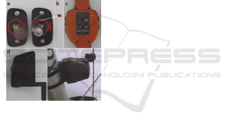
During the analysis of the battery mould in the
sensor cover it turned out, that the selected SC could
directly replace the lithium cell battery with few
modifications in the sensor housing and at the
soldering lugs of the SC (Fig. 4a). Therefore, the
sensor was connected directly as supply to the
electrical sensor supply inputs in the fist practical
use tests. The consequence is that the exploitable
voltage range of the SC had to be limited to a frame

between 3.3 Volts down to 2.7 Volts. One further
discharge test with these new limits showed that
type C
x
can provide more than 60 minutes sufficient
supply voltage at the expected discharge current of
the used HR sensor. In the following work, several
use tests have been performed in this simplified way
and the implementation of the regulator circuitry in
the test sensor was postponed to a later experimental
phase.
The SC part sample of type C
x
with the smallest
self-discharge rate was selected, so that the power
consumption of the sensor in sleep mode could also
be determined and qualified accurately. In a first
laboratory experiment, the SC was charged to the
maximum allowed input supply voltage with the
board in Figure 2. Then it was installed inside the
closed cover of the HR sensor. With a proprietary
smartphone App and a sports watch in parallel the
operation of the sensor was observed, while it was
worn for the next hour by an experimenter. During
this phase, only lab working activities, but no strain
sport actions, were performed, Table 5 list in its first
row the measuring results for this cycle.
Table 5: First documented test runs of the HR sensor
supplied from the SC cell: the columns show the voltage
just before installing the SC in the sensor and the voltage
immediately after removing the SC.
use mode
overall time
frame
just
before
directly
after
normal work, no
physical strain
09:08-10:17 3.29V 2.99V
slow jogging on
natural trail
10:38-11:43 3.31V 3.03V
The measured voltage drop of 0.3 Volts in the
first practical use of more than an hour suggested
that the SC-supplied sensor is directly feasible for a
first field test. For this, an endurance training was
performed in terms of a controlled slow jogging for
one hour at a constant speed of 6.5 mph (lower row
in Tab. 5). In this experiment, the HR sensor was
connected to a wearable sports computer, from
which the recorded running data can be transferred
to software running on a personal computer, in order
to display the results in bigger screen collections and
plotting graphs.
The whole system worked during the exercise
without problems and in a way as known from the
normal HR sensor use. In this run, there was some
additional preparation time for dressing and moving
between laboratory space and the running path
outside the building. Again this experiment showed
that the simplest concept easily supplies the HR
sensor for one full hour while consuming only half
of the available capacity. In other words, the ANT+
HR sensor can be operated in this configuration for
at least two hours plus several minutes for setup and
preparation times.
According to these first positive results, a longer
sensor test with a complete use cycle was prepared.
Since one of the two chest strap connectors on the
sensor housing (unit S in Fig. 1) is directly
connected to Ground level on the sensor board, only
one other electrical access point to the positive pole
of the SC was required. This was established by
drilling a hole into the back cover case above the
battery mould. After this, the SC could be firmly
enclosed into the sensor housing, since charging and
voltage measurement was now available through
access from outside. Few undocumented
experiments with slight overcharging, observation
and validation of the SC-supplied HR sensor had
been conducted in the following working phase.
After all, participating a public street run over
half-marathon distance was prepared in terms of
complete and quite regular handling cycle by a
sports person using and wearing the modified sensor
unit. The running event took place in 50 mi distance
from the laboratory environment, therefore typical
activities like traveling to the event place, registering
for the run and changing clothes was part of this
extended field experiment. Table 6 protocols the
relevant steps in this experiment.
Table 6: Protocol for the stages in attending a street
running competition with the SC-supplied HR sensor.
time mode/action measure
09:15am charging for 1 min 3.40V
09:30am test after settling time 3.37V
11:30am quiescent discharge test 3.35V
11:40am activation + walk to start
12:01am race start
01:42pm cross finishing line
01:50pm entering sensor sleep mode 2.27V
Unfortunately, correct HR recording failed
already 10 minutes after the run was started. After
leaving the race place and when the sensor entered
sleep mode, an unexpected deep discharge of the SC
had to be detected. In the following phase of the
investigation, it was found that humidity collected
inside the sensor caused the partial failed of the half-
marathon experiment. Several additional field tests
on nature trails and inspections of the sensor
unveiled, that the sealing of the sensor casing has to
be improved in the further work. Despite this
unexpected problem, the entire phase of the event
participation, which started with sensor charging,
then continued with preparation of the event
attendance and running the first mile, has shown,
that the SC capacity can supply a complete handling
cycle when attending such a sports event of two
hours duration. The SC discharge, which was
contributed by the HR sensor in sleep mode, is
found being negligible, hence no particular
expedition with the sensor in sleep mode is required,
even when conducting a two-hour workout with this
very simple power cell concept.
3.2 Regulated SC Power Supply and
Extended Field Test
For the final working stage in this context, a SC was
implemented firmly together with a linear voltage
regulator circuit (Fig. 4b) into the battery mould of
the HR sensor's back case (Fig. 4a). Charging and
measurement access was enabled through a
connection wire, which was fixed on the front of the
cover case as this side is not touching the skin. The
housing was closed mechanically and the system
was made watertight properly with electronic tape.
After the first test runs, it turned out that as well the
plus contact on the front side had to be electrically
insulated, because this contact point also started to
distort HR measurements as soon as the touching
clothes of the experimenter became moist from
sweat. Accordingly, the charge access pin was
modified further, so that it can be contacted by a test
prod, but it is protected against unintended electrical
contact of other items like wet shirts. As regulator
IC a type was selected, which has got low voltage
drop and ultra low power dissipation. Despite this
and according to its specification, the voltage
regulator increased the self-discharge rate of the
power supply, while it expanded the usable voltage
span of the SC from 2.8 Volts up to theoretically 5.5
Volts. Under the assumption, that in practice a wired
USB cable charger provides 5 Volts only, this value
was applied as upper charging voltage limit in all
further tests.
The following experiments (Tab. 7) yielded, that
the discharge rate of the regulated power cell is
again approximately 0.3Volts/hour for the SC with
one Farad true capacity. The self-discharge rate of
the expanded supply system with regulator IC was
observed being increased by approximately 1/3. For
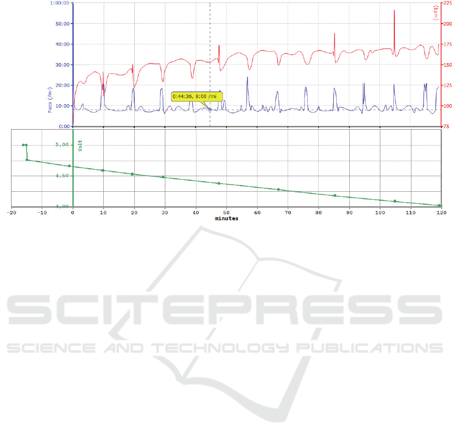
the final test shown in Fig. 3, a natural trail run was
decided, which should cover half-marathon distance
and should last two hours. During this workout, the
decaying capacitor voltage was measured with
equipment, which was carried in a rucksack. For
practicability of the voltage measurements during
the test trail, the run-walk-run method was applied,
which is proposed and advertised by a runners
coach, who is successfully active since many
decades in this sports field (Galloway, 2017).
Figure 3: A half-marathon was covered by the run-walk-run method as reflected in the middle function plot, which
displays the moving pace in units of minutes per mile. The lower curve shows the SC voltage, which was measured in the
one minute walking breaks. This plot starts 15 minutes before the run with one minute charging at 5 Volts. The uppe
r
functional graph shows the HR curve, which suffers from distortion peaks induced by the voltage measurements.

In this mode, the moving speed alternates
between quicker running for one mile and relaxation
phases for one minute at walking speed, which
causes dynamics in the corresponding HR trace. In
the strain pauses, the voltage measurements were
performed. Since the Ground contact of the sensor is
also used as skin electrode for HR detection, the
connection of the digital voltmeter disturbed the
very sensitive HR monitoring. This is reflected as
spurious distortion peaks in the HR curve in Fig. 3.
The preparation of the trail run started 1/4 hour
earlier with charging the SC for a minute with 5
Volts. Immediate measurements after the charging
showed, that the SC can not sustain the end voltage,
which refers to the fundamental property of
supercapacitors that their internal resistance is
increasing with accumulated charge. This implies
that a connection of the loading voltage for just one
minute is not sufficient for injecting the full
electrical load. Nevertheless, also the partial load is
already sufficient for longer workouts as seen here.
Table 7: Tests of the HR sensor supplied from the SCC
with voltage regulation.
use mode lab work trail run
charging method
@3.4V for
one minute
@5.0V for
one minute
active time frame 04:43-05:43 10:38-11:43
voltage at use start 3.29V 4.39V
voltage after use 2.95V 4.01V
Together with this final trail running experiment,
the findings about the new power supply can be
summarized as follows: 1) The usable voltage range,
which can be practically harvested from the SC
supply, is reduced, especially under the assumption
of USB cable charging for a limited time; 2) the
sensor should be used early after charging; 3) a one
minute charge load for a one Farad SC is capable of
operating an ANT+ HR sensor for reliably more
than six hours. Overall, the construction renders
feasible for typical workouts in sports and health
exercises, since these use to last around one hour as
discussed above.
3.3 Further Aspects on Design
Convenience
The selected capacitors have got a slightly bigger
size and a higher weight than a lithium battery cell,
while their price is similar or even lower. All these
differences are not high, but still consequence
modifications of the sensor housing. If the complete
SC voltage band is exploited and the sensor
operation time is specified to the typical value of one
hour plus - reasonably - 200% extra reserve, a
smaller and cheaper SC can be used, especially in
ANT+ devices. This means, that the sensors could
be constructed more slim and lightweight, which
would provide a further handling benefit.
4 DISCUSSION OF RESULTS
AND COMPLEMENTING
CONCEPTS
The experimental results and the proof-of-concept in
several field tests have shown here that the lithium
battery cell in sports and health sensors can be
replaced by an appropriately selected supercapacitor.
Already with a very simplified, direct connection of
the one Farad SC power cell an operational time of
more than two hours can be achieved for the most
typical unit of a heart rate sensor. When adding a
voltage regulator in the supply path (Fig. 4b), the
usable voltage range can be increased from (3.3-
2.7)Volts to (5.0-2.8)Volts, which stands for a factor
of approximately 3.5 and by that an operational time
with one single charge of at least seven hours. This
certainly will be enough for most personal
applications, only in extreme cases like attending an
Ironman Triathlon this supply capacity wouldn't be
sufficient.
It has to be noted that this efficiency applies in
such extend to ANT+ sensors, the more universal
systems with Bluetooth low Energy would reach -
due to their higher power consumption - only in the
order of 2.5 hours total operational time, which is
also sufficient for 80% of non-elite sports people
(USD Labor, 2009). The electrical power
consumption of other sensors are very similar to the
HR units, because most energy is required for their
RF transmissions. The voltage regulation has to be
performed in the experiments here with an additional
semiconductor circuit, because the sensor unit
represents a black box with non-transparent
internals, which cannot be modified.
For a final product on the market, the sensor
manufacturers can simply integrate the expanded
regulation into the device without additional effort in
electronics, since stabilization of supply voltage has
to be implemented anyway always. When using
instead of linear regulation so-called voltage pumps,
the supply band could be expanded towards much
lower SC output voltages, which would then
factorize the working time by another value of
approximately 1.5. Hence, with this improved
supply electronics, also BT sensors can reach a very
reliable operational duration.
Using a supercapacitor as power cell of a sensor
provides a series of advantages for construction and
manufacturing, for usability and for environment.
The SC would be implemented firmly inside the
sensor housing, therefore no mechanisms are
required for manual exchange by the user.
Considering, e.g., sensor S in Fig. 1, six mechanical
parts could be omitted in the design, which are in
detail the four screws, the backside cover and a
sealing ring. Furthermore, the sensor housing case
could be simplified. This all saves development
costs and even in fabrication by multiplication with
a high count of produced units, the costs for raw
material, production processing stages and
production cycle time.
Figure 4: Collection of devices for discussion of charging
concepts: a) backside mould of the open case of sensor S,
and the installation of the SC plus required electronics b)
voltage regulator IC installed left hand; c) commercial
solution of contacting device for charging; d) pedal and
wheel turning sensors as samples without regular contacts
but battery mould.
The price of the lithium battery cell, which is
usually contained in newly sold sensor packages, is
even higher than the one for a SC. Either the selling
price of the sensor could be reduced, which would
represent a customer benefit, or the earnings
statement for the vendor could be slightly improved.
The cumbersome handling of changing batteries like
discussed before could be avoided completely,
which represents evidently an important benefit for
the customer. Using a self-sustaining power cell is
obviously more environment-friendly than any type
of throw-away batteries, especially those wasting
rare earth metals. Capacitors provide advantages
even more compared to accumulators, because the
number of charge/discharge-cycles is almost
unlimited, and the capacitor cannot be destroyed by
deep discharge. This all preserves a much longer use
of SC-supplied sensors than when using
theoretically micro accumulators, and therefore
again an improvement of environment-friendliness.
One other important aspect hasn't been covered
in the discussion up to here: The question how the
SC can be charged prior to sensor operation appears
also relevant for the degree of handling convenience.
For HR sensors, which are equipped with electrodes
for their sensor inputs anyway (Fig. 4a), the
charging could be performed by a DC cable
connection through these connectors as well. For
other types (Fig. 4d), which do not have any
electrical connectors to outside, any kind of plug
adapter would be required, but for this technical
solutions are known and widely in use like, e.g., for
charging sports watches (Fig. 4c). For such cases,
some additional technical effort would be incurred.
Use of a charging cable would map perfectly to USB
connectors, which are known worldwide as universal
system for charging small units and which is
partially even enforced by laws. A more modern
solution would be inductively charging through an
RF field; this would require additional components
in the electronic circuitry of the sensor, but may
keep the mechanical design of the its housing
simple.
Contact-less charging represents a comfortable
method, if the charge loading is limited to a
reasonable time span, but even more modern would
be a complete self-supply of electrical sensor energy
as discussed for medical applications (Bachmann et
al., 2012). Sourcing heat dissipation from the human
body for generating the required electricity (Thielen
et al, 2017) would be another prospective concept, in
sports activities similar ideas would be possible with
tapping mechanical acceleration forces.
It shall be remarked at this concluding point, that
the study here is aiming just for achieving
fundamental findings and for demonstrating the
applicability of a relatively new components
technology in electronics to a new field of use. The
development of certified and professional sensor
products is deferred to companies, who want to
implement such ideas into new product generations
feasible for mass production and long-term use in
health and sports sensing.

5 CONCLUSIONS
As it has been demonstrated and validated in the
experiments here, supercapacitors sustain enough
electrical power for operating wireless body sensors
for a reasonable duration in sports workouts.
Therefore, super capacitors can replace the
commonly used lithium battery cell in terms of a
much more environment-friendly part for typical use
cases. In addition, mechanical sensor construction
can be simplified, since no exchange of the power
cell has to be regarded any more, and all
cumbersome manual user handling of this can be
completely avoided. Hence, the supercapacitor
solution arises more comfortable and cheaper than
using lithium batteries.
Physical workouts are limited for most people to
a duration around one hour; during this time frame
the one Farad SC easily delivers enough energy for
operating sensors with ANT+ or Bluetooth LE, even
if only a limited supply voltage range like the one of
lithium batteries is exploited. Depending on the
effort, which is invested in the power regulation
electronics, an expanded voltage band can be
harvested from the SC and the operational time can
be factorized considerably, which means that, e.g.,
an ANT+ HR sensor can be used up to half a day
without recharge.
SCs can be reloaded in practice for an unlimited
number of repetitions, and they cannot be destroyed
by deep discharge; hence, SCs provide also clear
advantages over the possible, alternative use of
micro accumulators. Since feasible SCs have got
similar size and weight like the lithium battery cells,
there remains no deterioration or restriction during
their use as sensor energy supply.
Preparation of the sensor use, on the other hand,
represents indeed an aspect of handling convenience,
which has not been covered intensely in this study so
far. Therefore, the concept work of this investigation
will be continued by developing and testing
improved discharge and recharge mechanisms like
contact-less methods and voltage-pumping. The
resulting increased duration for the sensor supply
will be validated with further practical experiments,
especially also for Bluetooth sensors with higher
power dissipation, because Bluetooth reaches almost
all modern smartphone devices and this may inspire
more people for performing also healthy sports
activities.
Up to here, this investigation has shown clearly
the potential, that supercapacitors can be used as
more comfortable, more cost-efficient and more
environment-friendly power supply than the
established solution of using throwaway lithium
cells in sport sensors.
REFERENCES
Arts, F. J., Kuipers H., 1994. The relation between power
output, oxygen uptake and heart rate in male athletes.
Int. J. of Sports Medicine, Vol. 15, No. 5, pp228-231.
Bachmann C., et al., 2012. Low-Power Wireless Sensor
Nodes for Ubiquitous Long-Term Biomedical Signal
Monitoring. IEEE Communications Magacine, vol.
50(1), pp 20-27.
Bluetooth SIG,
https://developer.bluetooth.org/DevelopmentResource
s/Pages/White-Papers.aspx, last access: April 2017.
Conway, B.E., 1999. Electrochemical Supercapacitors,
Scientific Fundamentals and Technological
Applications. Springer Science+Business Media, New
York, USA.
Dynastream Innovations Inc., 2011. ANT message
protocol and usage. http://thisisant.com, Rev. 4.5
(2011).
Galloway, J., Run Walk Run: It began in 1974.
http://www.jeffgalloway.com/training/run-walk/, last
access: July 2017.
Jefferis, B.J. et al, 2014. Protective Effect of Time Spent
Walking on Risk of Stroke in Older Men. Stroke, vol.
45, pp 194-199.
Lu, M., 2013. Supercapacitors: Materials, Systems and
Applications. John Wiley and Sons Inc., New Jersey,
USA.
Malkinson T., 2009. Current and emerging technologies in
endurance athletic training and race monitoring. In
TIC-STH 2009, Science and Technology for Humanity.
IEEE, Toronto, Canada, pp. 581-586.
Oguma, Y., Shinoda-Tagawa, T., 2004. Physical activity
decreases cardiovascular disease risk in women.
American Journal of Preventive Medicine, vol. 26(5),
pp 407-418.
Thielen, M., et al., 2017. Human Body Heat for Powering
Wearable Devices: From Thermal Energy to
Application. Energy Conversion and Management,
vol. 131, pp 44-54.
Tudor-Locke, C., Basset D.R., 2004. How many steps/day
are enough? Preliminary pedometer indices for public
health. Sports Med., vol. 34(1), pp 1-8.
Weghorn, H., 2015. Usability and Engineering Aspects of
Competing RF Technologies for Communication with
Commercial Sports Sensors in Ubiquitous
Applications - Experimental Comparison of Power
Consumption and Use Cases for ANT+ and Bluetooth
Low Energy Sensor Devices. In icSPORTS 2015, 3rd
International Congress on Sports Science and
Technology Support, SCITEPRESS, pp 263-270.
USD Labor, 2009. Sports and Exercise. Spotlight on
Statistics, May 2009, https://www.bls.gov/spotlight/
2008/sports/, last access: June 2017.
