
Algorithms of Aircraft Flight Parameters Determination via the
Visual Data
Sergey Sokolov, Nikolay Beklemichev and Andrey Boguslavskiy
Keldysh Institute of Applied Mathematics, RAS, Miusskaya Sq. 4, Moscow, Russia
Keywords: Aircraft, Flight Parameters, Computer Vision System, Altitude, Pitch, List, Unmanned Aerial Vehicle.
Abstract: This paper provides the information about the possibility of independent information channel development
for determination of altitude, list and pitch of aircrafts based on the visual data analysis. All stages of solving
the information support problem for aircraft control system based on the collection and processing of the
visual data are considered here. This paper provides the information about the development of mathematical
model, the calibration of visual fields and the provision of stereoscopic calculations accuracy. The
mathematical support of the computer vision system, consisting of two video cameras and computing unit
installed on the aircraft, is also described here. The proposed algorithms are implemented for the system
model as a part of the flying laboratory. The results of the experiments carried out for this model are also
presented here. The results allow drawing the conclusion about the possibility of successful solution of the
problem. Possible ways for further system improvement are also presented in this paper.
1 INTRODUCTION
Achievements of video equipment, computer
facilities, algorithmic of visual data acquisition and
processing allow considering a question of creation
economically expedient computer vision systems, for
the solution of problems of aircraft control systems
information support. Now a large number of
developments of unmanned vehicle is developed.
Vision systems as a part of systems of information
support play the increasing role, especially at the
solution of tasks in the conditions of uncertainty.
Unmanned aerial vehicles get the increasing degree
of autonomy. Messages on the solution of such tasks
as automatic UAV takeoff and landing on an aircraft
carrier, refueling of UAV in air are known (lenta.ru,
2012). Realization of VS advantages demands
overcoming of a number of problems. Large volume
of data which should be processed on the scale of real
time demands powerful computing tools and effective
processing algorithms.
In our work we decided to estimate a possibility
of determination of height, a list and pitch of aircraft
based on the visual data analysis. A practical
inspection of the developed software was performed
on the VS model which was established onboard of
the flying laboratory.
2 ESTIMATION OF ERROR IN
POINT HEIGHT
DETERMINATION VIA
STEREO IMAGES
The first step of studies was the estimation of the
error, with which the flight altitude can be determined
based on the visual data of the stereo system.
The scheme of calculation of an error of
determination of altitude according to a stereosystem
data is given in fig. 1. From the known formulas for
stereosystems (Lobanov, 1984; Hartley and
Zisserman, 2003) we will receive formulas for an
error estimation.
1) The value of the stereo depth depending on the
parallax:∙/, where is the stereo depth of
the point (meters), is the focal length (pixels), is
the stereo base (meters), is the point parallax
(pixels). Therefore, lnln, and
. The relative error in the stereo depth
determination is equal to the relative error in the
parallax determination.
2) Substituting from step (1) and omitting the
error sign, we obtain
/ or
/ (considering that 1 pixel) – the
494
Sokolov, S., Beklemichev, N. and Boguslavskiy, A.
Algorithms of Aircraft Flight Parameters Deter mination via the Visual Data.
DOI: 10.5220/0006477504940501
In Proceedings of the 14th International Conference on Informatics in Control, Automation and Robotics (ICINCO 2017) - Volume 2, pages 494-501
ISBN: Not Available
Copyright © 2017 by SCITEPRESS – Science and Technology Publications, Lda. All rights reserved
connection between the stereo depth and the error
in its definition.
3) The error in the determination of the point
position in the plan is equal to
/ – the size
of single pixel in the plan at the depth.
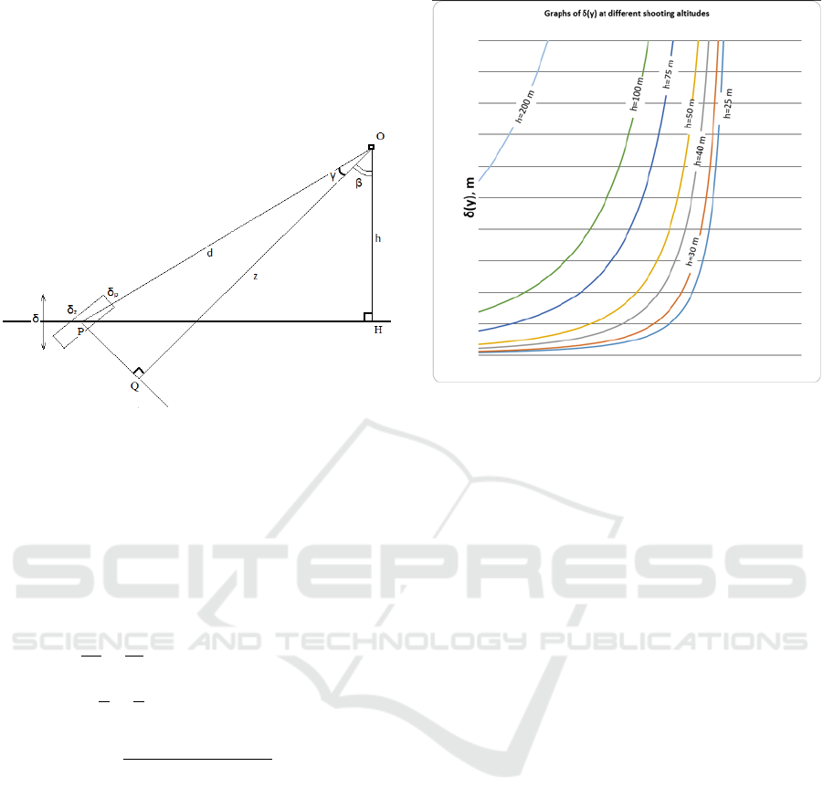
Figure 1: The scheme for calculating the altitude
determination error via the stereo system data: is the
projection center, is the point on the ground, is the
projection of the point on the ground, is the ground
(horizontal), , is the optical axis, .
Let us denote, is the range,
– is the stereo depth of the point P. Then
coscos/cos, and the formulas for
errors in the depth and in the plan are
cos
/cos
(1)
cos/cos
(2)
The error in the altitude determination is
cos
sin
(3)
Here is the angle of the optical axis inclination
to the vertical (fixed), arctg
/, is
variable line number (pixels from 0 to 1200),
is the
fixed line number of the main frame point.
The graphs of the error dependence in
determining the height of the point on the image
line number of for different values of the shooting
height are shown below.
We used the data of the system model, on which
the experiments were carried out (fig. 2 and
Section 5), as qualitative values of the parameters.
The parameters being used: The number of image
lines is 1200. The focal length = 1500 pixels. The
main point in the 600th line (
= 600). The stereo
base = 1,5 meters. The angle of the optical axis
inclination to the vertical = 75° (5π/12).
Figure 2: Theoretical graph of the altitude determination
error dependence on the frame line number (the lines are
numbered from the bottom up).
Therefore, some relevant information on the flight
altitude can be obtained only when shooting at the
altitude of not more than 150 m using the stereo pair
with the stereo base of the order of 1,5 m and = 75°.
3 CALIBRATION OF VIDEO
CAMERAS
The calibration of fields of view (the orientation of
video cameras) is the important stage in the computer
vision system preparation for measurements. The
orientation of video cameras includes internal
orientation and external orientation. To calculate the
parameters of internal and external orientation
(calibration) we used our own program, similar to that
available in OpenCV library (MatLab, 2016;
OpenCV, 2016).
The calculation of internal orientation consists in
determining the coordinates of the main frame point,
the focal length and the distortion parameters. Images
of a chessboard at various angles was used as initial
data. Actually in calculating the internal orientation,
when solving the corresponding system of equations,
the residuals were about 0.7 pixels on average and 3
pixels maximum, that is the distortion was almost
completely compensated.
External orientation consists in determining the
projection matrix elements and the projection center
coordinates for each camera in the aircraft coordinate
system. One frame was used as initial data for each
Algorithms of Aircraft Flight Parameters Determination via the Visual Data
495

camera with marked reference points (points with
previously measured 3D coordinates). The reference
points were marked on the hangar floor so that not
less than 4 points were in the vision field of each
camera (13 points were used in total). Then they were
manually assigned approximate coordinates with
respect to the aircraft with the accuracy of 1 m. After
that the pairwise distances between the points were
measured using measure tape. Then the coordinates
were defined by our own program using the least
square method. The residuals in the determination of
coordinates from the values of pairwise distances
measurements were equal to 1 cm maximum and 0,3
cm on average.
The residuals in the calculation of external
orientation were equal to 4 pixels on average and 7
pixels maximum. This result leaves much to be
desired. The reason is that many of reference points
of the frame were not clearly visible because of the
glare. According to the calibration results the stereo
base is 1,33 m.
4 MATHEMATICAL MODEL –
CALCULATION FORMULAS
FOR FLIGHT PARAMETERS
DETERMINATION
We consider flat relief model as the approximation,
i.e. we assume that the flight is carried out above the
plane. At that the images for left and right cameras
after correcting deviations caused by the distortion
will be connected by some projective transformation.
Let’s additionally suppose that both images are
obtained simultaneously. Then we can obtain the
elements of the connective projective transformation
matrix, depending on the coefficients of the ground
plane equation, by recording the ground plane
equation in the aircraft coordinate system with
indefinite coefficients and knowing the parameters of
external orientation of both cameras in the aircraft
coordinate system. On the other hand, we can find
some common points on left and right frames using
the correlation and then find the connective projective
transformation matrix by the least squares method
after correcting the deviations of the points
coordinates caused by the distortion. Now by making
these two matrices equal to each other we obtain the
overdetermined system of 9 equations (according to
the number of matrix elements), from which we can
find the desired ground plane equation the in the
aircraft coordinate system, and thereby we obtain the
estimation of the flight altitude and the angles of list
and pitch of the aircraft.
Assume that and ´ are the focal lengths of left
and right cameras in pixels. Assume that and ´ are
the centers of left and right cameras projection in the
aircraft coordinate system,
,
,
and
,
,
are basis unit vectors related to left and right cameras
(
– in the frame line from left to right,
– in the
column from top to bottom,
– from the camera to
the object (orthogonally to the e
1
e
2
plane). Assume
that and ´are orthogonal matrices with the lines
and
respectively (the projection matrices),
´is the stereo base vector.
Assume that
〈
,
〉
is the ground plane
equation in the aircraft coordinate system, where
,, is variable spatial point, is normal unit
vector to the plane,
〈
,
〉
is the scalar product.
Assume that , and ´,´ are the pixel
coordinates corrected for the distortion in relation to
the main point on left and right frame respectively.
Let us denote
and ´
´
´
´
.
Then the spatial points, projecting to the point
,, lie on the straight line
Here denotes the matrix transposition. This
straight line intersects the ground plane when
〈
,
〉
〈
,
〉
〈
,
〉
〈
,
〉
〈
,
〉
Here
〈
,
〉
is denoted as the distance from
the point to the ground plane. The condition that the
point is projected to the right frame at the point
´,´ is written as follows: ´∙
´
∙´,
where is the numerical factor. After that by
substituting the expression for we get:
´∙
〈
,
〉
´∙´
´∙
〈
,
〉
〈
,
〉
∙´
´
´
〈
,
〉
∙´
´
´
〈
,
〉
∙´
Therefore, the connective projective
transformation matrix with the accuracy up to the
proportionality coefficient is
´
´
= ´
´
where the vector
is the vector of length,
which is equal to
and proportional to the vector
, factorized on the basis
,
,
. Hence, we obtain
ICINCO 2017 - 14th International Conference on Informatics in Control, Automation and Robotics
496

the following matrix equation for the known matrix
of the connective projective transformation
´
´
(4)
with unknowns and , from which we find the
coordinates of the vector , solving the
overdetermined system of 9 linear equations with four
unknowns by the least squares method (4). After that
we obtain the estimation of the flight altitude
1/
|
|
and the coordinates of the vector in the
aircraft coordinate system as
. The
estimations for the angles of list and pitch with
the known are obtained from the following
condition
10 0
0 cos sin
0 sin cos
cos 0 sin
01 0
sin 0 cos
0
0
1
From which arcsin
, arcsin
/
, where
,
,
Let’s make a remark about the summand ´
in
the matrix equation. For →∞ we have →.
Therefore, ´
is the connective projective
transformation matrix for «infinitely high» flight
altitude (at infinity). And ´
is the correction,
which is the greater, the smaller the flight altitude and
the greater the stereo base.
5 DIFFICULTIES IN PRACTICAL
IMPLEMENTATION OF
FLIGHT PARAMETERS
DETERMINATION
5.1 Synchronization of Left and Right
Cameras Images
Without the special external device forming
synchronization impulses in the shots received from
video cameras the relative shift making units of shots
is observed. When giving clock pulses from one of
stereo pair camera on another shots are synchronized,
but the frequency of delivery of these shots steadily
decreases. Taking into account that the task of supply
with information of a control system of the aircraft on
a responsible site of landing – the movement on a
glide path is set for VS, the decision to leave the
maximum frequency of delivery of shots, and the
found mismatches on time to compensate
algorithmically, in processing of visual data was
made.
The formulas of the previous paragraph are valid,
if left and right frames are received strictly
synchronized. Actually, this is not the case. The
frames are received through the network
independently from left and right cameras and can be
out of sync for up to 0,2 seconds. During this time the
plane is able to move to the distance much greater
than the stereo base that was found during the
calibration.
To compensate for this effect, we proceeded as
mentioned below. At first, regular grid of points is
recalculated by the correlation (Beklemishev, 2016)
from the left frame to the right frame (fig. 6). At that
processing the epipolar correspondence (Lobanov,
1984; Hartley and Zisserman, 2003), as a rule, is
broken because of the desynchronization. For the
point on the left frame, its correlation pair on the right
frame does not lie on the epipolar calculated on the
basis of external orientation data.
Then another regular grid of points is recalculated
by the correlation from the previous frame of the right
camera to the current frame of the right camera
(fig. 7). According to these data after correcting the
deviations of points coordinates caused by the
distortion using the least squares method, the average
projective transformation from the previous right
frame to the current right frame is found. According
to this transformation, the sparse optical flow is
calculated on the right frame: the displacement vector
is determined for each point.
Finally, a pair of points, which corresponds on
correlations of left and right frame, is considered for
known optical flow and built on the epipolar right
frame. It corresponds to the point on the left frame.
Then the point on the right frame is transferred along
the optical flow to the epipolar. Therefore, the
correspondence for each point on the left frame is
determined in two stages: at first by the correlation,
and then the found point is transferred to the epipolar
along the optical flow (fig. 3, 4).
After that the connective projective
transformation matrix is being found on the built
pairs of points from the left frame to the right frame,
which is used for estimation of the flight altitude as
described above.
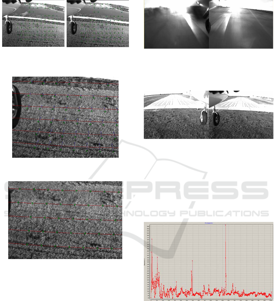
Figure 3: Points distributed along the regular grid on
epipolar lines on the left frame and recalculated by the
correlation to the right frame. The deviation of points from
the epipolar on the right frame and the the epipolar
deviation because of the lens distortion is notable.
Algorithms of Aircraft Flight Parameters Determination via the Visual Data
497
(а) (
b
)
Figure 4: Regular grid of points recalculated by the
correlation from the previous right frame to the current one.
Figure 5: Points on the right frame recalculated by the
correlation from the left frame and the optical flow.
Figure 6: Points on the right frame recalculated by the
correlation from the left frame and transferred to the
epipolar by the optical flow.
5.2 Conditions of Image Capturing
It is not possible to align left and right images by the
correlation, when image capturing occur in difficult
conditions (landing against the sun (fig. 7), glare,
landing above the terrain without contrasting details
– snow, water).
Even at image capturing in good optical
conditions when approaching the flight strip and
flying over the flight strip, it is difficult to align the
left and right frames due to the lack of contrasting
details (fig. 11) at the top of the frame and because of
the
motion
aberration
at
the
bottom
of
the
frame.
In
Figure 7: The example of stereopair at the sunlight flash.
this case an improvement in the stereo algorithm is
required, using the alignment of the selected edges of
the flight strip.
Figure 8: The example of the complexity of images for
analysis because of underlying terrain uniformity.
When the flight altitude is restored using the video
example (glide-path capture, shooting at the altitude
of 80-50 m, 1011 frames, 40 seconds of flight), there
are emissions dependence on the frame number.
These emissions are associated with aircraft
maneuvers at glide-path capture. In such cases, the
model for compensating the desynchronization of
frames on the optical flow is no longer correct (fig. 9).
Figure 9: The errors of determination of flight altitude due
to maneuvers of the aircraft.
6 RESULTS OF EXPERIMENTS
The described algorithms were tested on the visual
data obtained by the vision system at the flying
laboratory (fig. 13).
ICINCO 2017 - 14th International Conference on Informatics in Control, Automation and Robotics
498
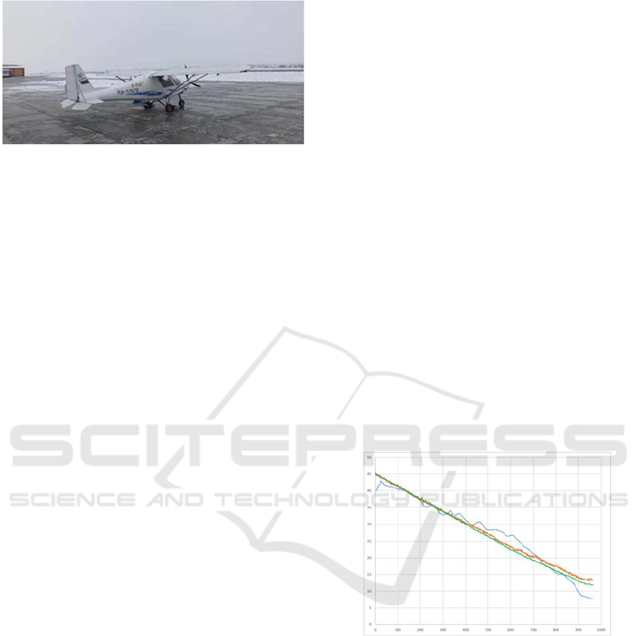
Figure 10: The Ikarus-C42 light plane onboard which the
flying laboratory for studying of means of information
support of aircrafts was organized.
Two video cameras ImiTech IMC-7020G were
installed on board light aircraft Ikarus-C42 along the
fuselage sides directed forward and down at the angle
of about 75° to the vertical with the stereo base of
about 1,3 m. The resolution of the cameras is
1600x1200 pixels, the frequency is 25 frames per
second, the focal length is about 1600 pixels (the span
angle is about 60°). The data were transmitted to on-
board computer Compulab IntensePC via Gigabit
Ethernet and recorded on the hard disk as
uncompressed AVI-file with resolution of 3200x1200
pixels. Each frame of the recorded video consisted of
adjacent frames of left and right cameras that were
transmitted simultaneously.
Simultaneously with the recording of the video
data the recordings of the integrated GPS receiver
SBG IN-500 (SBG Systems, 2017) installed on board
the flying laboratory have been fixed as well. This
device allows you to fix the position and orientation
of the aircraft with high accuracy.
Moreover, it has got a built-in barometric height
sensor. These data were used for comparative
analysis of measurement results based on visual data.
The unified software framework of realtime vision
systems developed by authors was the basis for
software implementation of the described algorithms.
This framework allows to increase efficiency of the
development process of an applied vision system.
Distinctive features of the offered approach to VS
software developing are (Boguslavsky, 2003;
Sokolov, 2016).
The VS software architecture provides a
possibility of cross-platform development on
the basis of universal personal computers and
fast transfer on special computing platforms
due to software decomposition into a set of the
interacting parallel subsystems.
The extendable subsystem of visual data
processing from several fields of view
providing processing in real time of video
sequences from visual sensors of high
resolution.
Using of reusable software components for
visual data processing for the software
prototyping.
Implementation of special debugging means
for ensuring reproducibility of software
functioning at a development stage and at a trial
stage.
6.1 Measurement
The following graphs (fig. 11-13) show the results of
calculations of the flight parameters of an aircraft
based on the processing of visual data (according to
the formulas from Section 4).
For comparative analysis, the same graphs show
data from an integrated SBG receiver (SBG Systems,
2017).
As a demonstration site, data were selected for the
landing glide path from a height of 40 to 4 m (1011
frames, 40 seconds of flight).
The frame number changes from 0 to 970. The last
40 frames could not be processed due to the poor
performance of the stereo algorithm while
approaching the runway, see Section 5.2).The frame
number changes from 0 to 970.
Figure 11: The altitude chart of the aircraft (in meters),
depending on the frame number obtained by processing the
visual data in comparison with the data of the integrated
GPS receiver. The blue line is the height according to the
visual data; Orange line – data of the barometric sensor
from the SBG receiver, green line – height according to the
GPS data of the SBG receiver.
Algorithms of Aircraft Flight Parameters Determination via the Visual Data
499
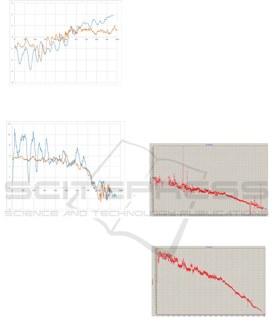
Figure 12: Graphs of the dependence of pitch (in degrees),
depending on the frame number. The blue line is pitch,
calculated on the basis of visual data processing; Orange
line - pitch according to the integrated GPS receiver.
Figure 13: Graphs showing dependencies of roll (in
degrees), depending on the frame number. The blue line is
the bank, calculated on the basis of visual data processing;
Orange line – roll according to the integrated GPS receiver.
6.2 Dependence of Time and Accuracy
of Calculations on the Quality of
Fields of View Alignment
The running time of the algorithm on the desktop PC
Pentium Dual-Core CPU 3,06 GHz at one processor
core is 0,18 seconds per frame (without considering
the time of frame loading into the memory). A
computer with these characteristics was installed on
board a flying laboratory. With its help, visual data
was collected and processed from a stereopair.
The processing of frames is carried out
independently. Only the current left and right frames
and the previous right frame are required to calculate
the values of altitude, list and pitch. Therefore, even
real-time processing of frames at the rate of 25 frames
per second is achievable, in principle.
This running speed is achieved by recalculating
regular grid of points (from the left frame to the right
frame and from the previous right frame to the current
right frame) by the correlation of 100 pixels in row
and column. At that 917 of 1011 frames (90.7%) were
processed. For others the correlation was estimated
by the program as unreliable. When calculating the
rarer grid, the running time is reduced, as is the
quality of the result. Figure 14 shows the graph of the
altitude change obtained by using the grid step of 200
pixels. At this step, 826 of 1011 frames (81.7%) were
processed and the algorithm running time was 0,048
seconds per frame without considering the time of
frame loading into the memory.
Figure 15 shows the graph of the altitude change
obtained by using the grid step of 50 pixels. At the
such step, 939 of 1011 frames (92.8%) were
processed and the algorithm running time was 0,676
seconds per frame, without considering the time of
frame loading into the memory.
Figure 14: The graph of the altitude change depending on
the frame number, the grid of points with the step of 200
pixels.
Figure 15: The graph of the altitude change depending on
the frame number, the grid of points with the step of 50
pixels.
ICINCO 2017 - 14th International Conference on Informatics in Control, Automation and Robotics
500
7 FURTHER RESEARCH
As it was noted in Section 5, practical realization of
the offered approaches revealed a number of
problems. Some from them were overcome, and a set
only demand the decision.
To improve the performance of the flight
parameters analyzer in the sunlight flash conditions.
It is planned to use the lens screen.
To improve the performance of the correlator
when shooting at low altitude on approaching the
flight strip and when flying over the flight strip. It is
planned to use the marking of the flight strip
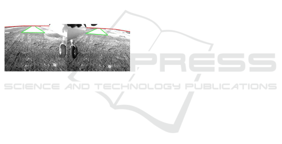
boundaries and other objects (fig. 16).
It is planned to use the marking of the horizon line
on the frame to obtain the estimation of the current
angles of list and pitch of the aircraft (fig. 16).
Synchronization of work of all algorithms taking
into account the scale of real time is carried out by a
large-scale framework of real time vision system
software (Sokolov,
2016).
Figure 16: Example of definition of a line of horizon and
runway borders in stereosystem fields of view.
To improve the accuracy of the flight parameters
analyzer. It is possible to use a synchronous pair of
video cameras, as well as more accurate calibration of
the stereopair in terms of external orientation.
Also in this case it is possible to exclude the use
of flat terrain model, provided that there is the matrix
of altitudes, which was previously received and
binded to the photographic plan.
8 CONCLUSIONS
The optical subsystem consisted of two video
cameras directed forward and down at the angle of
75° to the vertical with the stereo base of about 1,5
meters in good visibility conditions allows obtaining
stable estimation of the flight altitude, list and pitch
when flying in straight line at the altitude from 150 to
0 meters. Such subsystem can be useful for automatic
landing of unmanned aerial vehicles in good visibility
conditions.
ACKNOWLEDGEMENTS
This work was supported by the grants РНФ №16-19-
10705 and РФФИ №16-08-01282.
REFERENCES
News agency lenta.ru The USA have finished UAV X-47B
deck tests. URL http://lenta.ru/news/2012/12/20/x47b/
Lobanov, A.N., 1984. Photogrammetry, “Nedra”. Moscow,
552 pg.
Richard Hartley and Andrew Zisserman (2003). Multiple
View Geometry in Computer Vision. Cambridge
University Press. pp. 155–157. ISBN 0-521-54051-8.
Camera Calibration Toolbox for Matlab URL
http://www.vision.caltech.edu/bouguetj/calib_doc
OpenCV, 2016. OpenCV Library, URL
http://www.opencv.org
Beklemishev, N.D., 2016. Estimation of average parallax of
stereo images. In Preprints of M.V. Keldysh Institute of
Applied Mathematics, No. 88, 12 pg.
http://library.keldysh.ru/preprint.asp?id=2016-88.
Boguslavsky A.A., Sokolov S.M. Component Approach to
the Applied Visual System Software Development. 7th
World Multiconference on Systemics, Cybernetics and
Informatics (SCI 2003), July 27-30, Orlando, Florida,
USA, 2003
Sokolov S.M., Boguslavsky A.A. Layout for the
information support system for mobile vehicles based
on the real time vision system. // Proc. The 7th
International Multi-Conference on Complexity,
Informatics and Cybernetics: IMCIC 2016, March 8-
11, 2016, Orlando, Florida, USA, pp. 243-247.
SBG Systems, 2017. IG-500N: GPS aided miniature INS.
URL https://www.sbg-systems.com/products/ig500n-
miniature-ins-gps
Algorithms of Aircraft Flight Parameters Determination via the Visual Data
501
