
Conformance Checking in Integration Testing of Time-constrained
Distributed Systems based on UML Sequence Diagrams
Bruno Lima and João Pascoal Faria
Faculty of Engineering, University of Porto, Porto, Portugal
INESC TEC, Porto, Portugal
Keywords:
Model-based Integration Testing, Conformance Checking, Distributed Systems, Time Constraints, UML.
Abstract:
The provisioning of a growing number of services depends on the proper interoperation of multiple products,
forming a new distributed system, often subject to timing requirements. To ensure the interoperability and
timely behavior of this new distributed system, it is important to conduct integration tests that verify the inter-
actions with the environment and between the system components. Integration test scenarios for that purpose
may be conveniently specified by means of UML sequence diagrams (SDs) enriched with time constraints.
The automation of such integration tests requires that test components are also distributed, with a local tester
deployed close to each system component, coordinated by a central tester. The distributed observation of exe-
cution events, combined with the impossibility to ensure clock synchronization in a distributed system, poses
special challenges for checking the conformance of the observed execution traces against the specification,
possibly yielding inconclusive verdicts. Hence, in this paper we investigate decision procedures and criteria
to check the conformance of observed execution traces against a specification set by a UML SD enriched with
time constraints. The procedures and criteria are specified in a formal language that allows executing and
validating the specification. Examples are presented to illustrate the approach.
1 INTRODUCTION
In a growing number of domains, the provisioning of
end-to-end services to the users depends on the proper
interoperation of multiple products (devices, applica-
tions, etc.) from different vendors, forming a new dis-
tributed system, often subject to timing requirements.
Examples can range from sports monitoring applica-
tions (Taylor, 2015) to fall detection systems for se-
niors (Lima and Faria, 2016) or IoT systems.
To ensure interoperability and the timely behavior
of such distributed systems, it is important to conduct
integration tests that verify the interactions between
the system components and with the environment. In-
tegration test scenarios for that purpose may be con-
veniently specified by means of UML Sequence Di-
agrams (OMG, 2015) (SDs), because they are an in-
dustry standard well suited for describing and visual-
izing the interactions that occur between the compo-
nents and actors of a distributed system.
In previous work (Lima and Faria, 2016) we pro-
posed an overall approach to automate the integra-
tion testing in distributed and heterogeneous systems.
The only manual activity required is the description
of the participants and behavior of the services un-
der test with UML SDs. In the proposed approach,
a local tester is deployed close to each system com-
ponent, coordinated by a central tester. However, the
distributed observation of execution events by the lo-
cal testers, combined with the impossibility to ensure
clock synchronization in a distributed system, poses
special challenges for checking the conformance of
observed execution traces against the specification.
The main contributions of this paper are novel
decision procedures and criteria to check the con-
formance of distributed execution traces against a
specification set by a UML SD enriched with time
constraints. The procedures and criteria are speci-
fied in the VDM formal language (Fitzgerald et al.,
2005)(Larsen et al., 2016), which allows executing
and validating the specification. Examples are pre-
sented to illustrate the approach.
Section 2 presents background on our approach
for the integration testing of distributed systems; sec-
tion 3 presents the decision procedures and criteria for
conformance checking in the presence of time con-
straints; related work is presented in section 4; sec-
tion 5 concludes the paper.
Lima, B. and Faria, J.
Conformance Checking in Integration Testing of Time-constrained Distributed Systems based on UML Sequence Diagrams.
DOI: 10.5220/0006474004590466
In Proceedings of the 12th International Conference on Software Technologies (ICSOFT 2017), pages 459-466
ISBN: 978-989-758-262-2
Copyright © 2017 by SCITEPRESS – Science and Technology Publications, Lda. All rights reserved
459
2 BACKGROUND
In previous work (Lima and Faria, 2016) we proposed
a scenario-based approach for automating the integra-
tion testing of end-to-end services in distributed and
heterogeneous systems.
Test scenarios are specified using an accessible
front-end notation such as UML SDs, which are au-
tomatically translated to a back-end formal notation
suitable for efficient test input generation and confor-
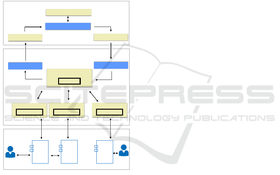
mance checking at runtime. At the end of test execu-
tion, test results (errors and coverage information) are
mapped back to the front-end notation (see Figure 1).
Visual Behavioral Model
Translation Tool
Modeling Tool
Mapping Tool
Formal Runtime Model
Test Results
…
Central Tester
System Under Test
Component
Under
Test
…
CUT
CUT
1
2
n
Distributed Test Generation and Execution Engine
Visual Modeling Environment
Global State
Local Tester 1
Local State 1
LT 2
Local State 2
LT N
Local State n
Figure 1: Architecture for model-based integration testing
of distributed systems (Lima and Faria, 2016).
We follow an online model-based testing (MBT)
strategy (or adaptive), to cope with non-determinism
common in distributed systems. In an online strategy,
test generation and execution are performed together,
allowing test inputs to be decided based on the outputs
observed so far (Utting and Legeard, 2007).
In order to be able to check not only the inter-
actions with the environment but also the interac-
tions between the components of the system under
test (SUT), we follow a hybrid test architecture, in
which a local tester is deployed close to each system
component, and a central tester coordinates the lo-
cal testers (see Figure 1). This is more effective than
a purely centralized approach or a purely distributed
approach, meaning that more conformance errors can
be detected (Hierons, 2014).
In the case of a component under test (CUT) that
interacts with actors (users or external applications)
in the environment (see Local Tester 1 in Figure 1),
the local tester is responsible for simulating the ac-
tors, injecting the inputs from the actors to the CUT
(acting as a test driver) and monitoring and checking
the outputs from the CUT to the actors (acting as a
test monitor). Besides that, it is also responsible for
monitoring all the messages exchanged between that
CUT and the rest of the SUT. In the case of a CUT
that does not interact with the environment (see Local
Tester 2 in Figure 1), the local tester is responsible for
monitoring and checking all the messages exchanged
between that CUT and the rest of the SUT, acting as a
test monitor.
In such a test architecture, it is important to mini-
mize the communication overhead during test execu-
tion, namely in the presence of time constraints. It is
equally important to detect errors as early as possible
and closely as possible to the offending component, to
provide more helpful test reports and facilitate fault
localization. To that end, besides the test monitor-
ing and control activities, model execution and con-
formance checking activities need also be distributed.
In more recent work (Lima and Faria, 2017) we
investigated distributed conformance checking but
without taking time observation and time constraints
into consideration.
3 CONFORMANCE CHECKING
WITH TIME CONSTRAINTS
As said before, conformance checking in the presence
of time constraints in a distributed system is specially
challenging. Hence, in this section, we investigate the
decision procedures and criteria to check the confor-
mance of observed execution traces against a speci-
fication set by a UML SD enriched with time con-
straints.
As in our previous work, the decision procedures
and criteria are specified with the VDM formal spec-
ification language (Fitzgerald et al., 2005)(Larsen
et al., 2016), to enable us to execute and validate the
specification with a support tool, such as Overture
(http://overturetool.org/).
Before investigating the conformance procedures
and criteria, we need to formalize the structure and
semantics of time-constrained SDs.
ICSOFT 2017 - 12th International Conference on Software Technologies
460

3.1 Time-constrained SDs
UML SDs may be annotated with time con-
straints (OMG, 2015). Although the UML standard
allows the specification of more complex constraints,
in this paper we restrict our attention to the types
of time constraints that are commonly addressed in
the literature of time-constrained distributed systems
(see Related Work) and are most relevant in practice:
constraints that specify the minimum and maximum
delays (time elapsed) between two events (message
sending or receiving) in the same lifeline, or between
the sending and receiving of a message between two
lifelines. We assume that the minimum and maximum
delays are constant values (or expressions that can be
evaluated before the scenario execution).
L2
m1
L1
e1
e2
e4
m2
{0..2}
{0..2}
{0..5}
e3
{0..2}
Figure 2: Example of a time-constrained SD.
Figure 2 presents a scenario with that type of
time constraints in UML. Each interval is denoted
{min..max}, where min or max can be omitted. De-
noting by ti the time instant of event ei, the only
valid execution trace defined by this SD is the time-
constrained trace [(e1, t1), (e2, t2), (e3, e3), (e4, t4)]
with t2 ∈ [t1, t1 + 2], t3 ∈ [t2, t2 + 2], t4 ∈ [t3, t3 +
2] and t4 ∈ [t1, t1 + 5]. An example of a valid
timed trace (with the time instant of each event) is
[(e1, 1), (e2, 3), (e3, 4), (e4, 5)]. An example of an in-
valid timed trace is [(e1, 1), (e2, 3), (e3, 5), (e4, 7)].
To check if an observed trace is valid, besides ver-
ifying if the observed events occurred by a certain or-
der, it is also necessary to verify if their time instants
satisfy the time constraints defined in the SD, as will
be formalized in the next two subsections. We start by
computing the valid time-constrained traces defined
by a SD.
In UML, an SD is a variant of an Interaction
(OMG, 2015). Figure 3 presents an excerpt of the
formalization of the structure of Interactions in VDM,
highlighting the elements added to support time con-
straints as compared to our previous work (Lima and
Faria, 2017). For simplicity, we omit the definition
of combined fragments (which can be found in our
previous work), integrity constraints, and some ba-
sic types. An Interaction comprises a set of lifelines
(representing in our case CUTs or actors), messages
(restricted in our case to asynchronous messages, al-
though synchronous messages could easily be han-
dled), combined fragments and time constraints. For
each message, we define the locations of the send and
receive events (sendEvent and receiveEvent), and
the (optional) variables that represent the instants of
time of occurrence of those events (sendTimestamp
and rcvTimestamp).
A TimeConstraint imposes minimum and max-
imum values on the time that can elapse between two
events (identified by the timestamp variables). Either
the minimum or the maximum may be omitted.
3.2 Valid Traces defined by a
Time-constrained SD
In general, the semantics of an Interaction is ex-
pressed in terms of two sets of valid and invalid traces
(OMG, 2015). In this paper, we don’t handle the
rarely used constructs for defining invalid traces (such
as the neg operator), so only the valid traces are rele-
vant here. A trace is a sequence of event occurrences
(OMG, 2015), corresponding, in this context, to the
emission or reception of messages at lifelines. Fig-
ure 3 shows the structure of traces in VDM with tim-
ing information, by means of an optional timestamp
associated with each event. Depending on the context,
the timestamp may be a variable (as in (e1, t1)) or a
concrete value (as in (e1, 1)). In this paper we assume
a discrete time scale (in an appropriate unit, such
as seconds or microseconds), but a continuous scale
would equally work. Hence, time instants (Time) and
elapsed time (Duration) are represented by natural
numbers.
Since we are dealing with distributed systems, we
assume there is no global clock, so time instants are
measured with the local clocks. Although it is impos-
sible to ensure perfect clock synchronization between
lifelines, in practice we can assume, like other authors
did (see Related Work), that there is a maximum dif-
ference (or skew) between the readings of any two
clocks (MaxClockSkew). For example, the Network
Time Protocol (NTP) (Mills, 1991), designed to syn-
chronize the clocks of computers over a network to a
common timebase (usually UTC), achieves synchro-
nization accuracies of 10 ms over Internet, and 1 ms
on LAN.
For computing the set of valid traces defined
by an Interaction with time constraints (see func-
tion validTraces in Figure 4), we first com-
pute the valid traces ignoring time constraints
(validTracesUntimed), following a procedure pre-
sented in our previous work for SDs without time con-
straints (Lima and Faria, 2017), and subsequently ex-
clude the traces for which the defined time constraints
Conformance Checking in Integration Testing of Time-constrained Distributed Systems based on UML Sequence Diagrams
461

types
Interaction ::
lifelines : Lifeline-set
messages : Message-set
combinedFragments: CombinedFragment-set
timeConstraints : TimeConstraint-set;
Message ::
id : MessageId -- unique
sendEvent : LifelineLocation -- unique
receiveEvent : LifelineLocation -- unique
signature : MessageSignature -- may not be unique
sendTimestamp: [Variable] -- unique
recvTimestamp: [Variable]; -- unique
LifelineLocation = Lifeline Location;
TimeConstraint ::
firstEvent : Variable --identified by timestamp var.
secondEvent: Variable-- identified by timestamp var.
min : [Duration]
max : [Duration];
Variable :: name : String;
Trace = Event*; -- seq of 0 or more
Event ::
type : EventType
signature: MessageSignature
lifeline : Lifeline
timestamp: [Variable|Time];
EventType = <Send> | <Receive>;
Time = ℕ;
Duration = ℕ;
TimeInterval = [Time] [Time]; -- (min, max) pair
values
MaxClockSkew : Duration = 10; -- configurable
Figure 3: Interactions and traces.
are not satisfiable (function isSatisfiable). A set C
of time constraints is satisfiable for a trace t if there is
an assignment of non-decreasing time instants to the
event occurrences in t that satisfies all the time con-
straints in C. Before explaining the procedure for de-
termining satisfiability, we start by presenting a run-
ning example.
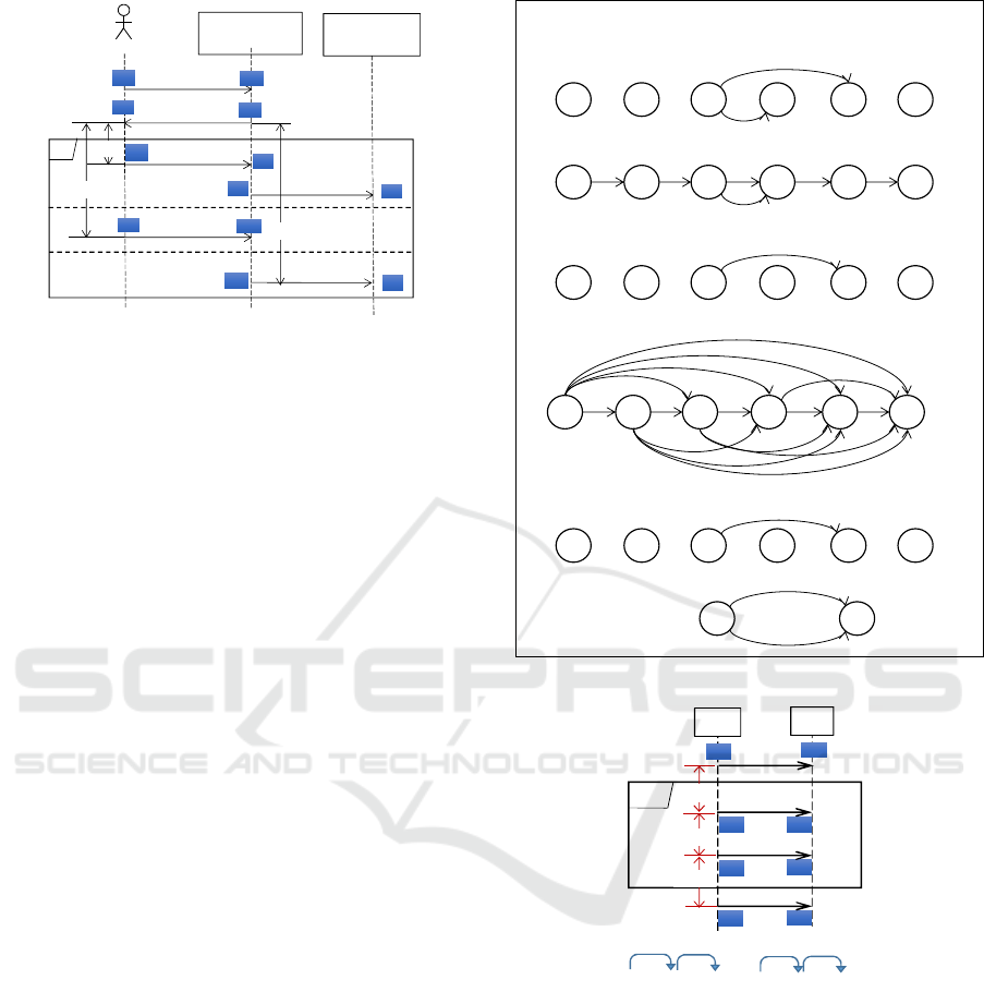
Figure 5 presents a SD that describes a real sce-
nario of a fall detection service. In this scenario, a
care receiver has a smartphone that has installed a fall
detection application. When this person falls, the ap-
plication detects the fall and provides the user a mes-
sage which indicates that it has detected a drop giving
the possibility for the user to confirm whether he/she
needs help. If the user responds that he/she does not
need help, the application does not perform any ac-
tion; however, if the user confirms that needs help or
does not respond within 10 seconds, the application
sends an alert to a web application called AAL4ALL
Portal. In addition to the time constraint of 10 seconds
between a reception of the confirmation request and
the user response, other time restrictions are also rep-
resented, namely one second as the maximum deliv-
ery time of the messages and 13 seconds between the
sending of the notification to the user and the sending
functions
-- Gives the set of valid traces defined by an
-- Interaction.
validTraces: Interaction Trace-set
validTraces(sd) ≜ {t | t validTracesUntimed(sd)
isSatisfiable(t, sd.timeConstraints)};
-- Checks if a set of time constraints (C), imposing
-- min/max delays between pairs of events, is
-- satisfiable for a trace t.
isSatisfiable: Trace TimeConstraint-set 𝔹
isSatisfiable(t, C) ≜
let cp = getConstrainedPairs(t, C),
minGiven= {mk_(i,i+1)↦0 | i {1,...,|t|-1}} ++
{mk_(i,j)↦c.min |
mk_(i,j,c) cp c.min nil},
maxGiven= {mk_(i,j)↦c.max |
mk_(i,j,c) cp c.max nil},
minDeriv= longestDistances(minGiven),
maxDeriv= shortestDistances(maxGiven)
in ∄ p dom minDeriv dom maxDeriv
minDeriv(p) > maxDeriv(p);
-- Given trace t and time constraints C, returns
-- tuples (i,j,c) of indices i and j of events in t
-- that are subject to a constraint c in C.
getConstrainedPairs: Trace TimeConstraint-set
(ℕ ℕ TimeConstraint)-set
getConstrainedPairs(t, C) ≜
{mk_(i,j,c) | i inds t, j inds t, c C
i < j
t
i
.timestamp = c.firstEvent
t
j
.timestamp = c.secondEvent
∄ k {i+1, ..., j-1}
t
k
.timestamp c.firstEvent,c.secondEvent}};
Figure 4: Valid traces defined by an Interaction with time
constraints.
of the alert message in case of no response.
In this example, if time constraints are ignored,
there are five valid traces (see Valid Traces Untimed
in Figure 5). The last two traces correspond to per-
mutations of the third trace in which event e4 occurs
after events e11 and/or e12. This happens because, if
time constraints are ignored, the presented SD doesn’t
impose any relative ordering between event e4 and
events e11 and e12. However, if time constraints are
considered, those traces are no longer valid. In fact, it
is easy to check that the defined time constraints are
not satisfiable for those traces: event e4 must occur
up to 1 time unit after e3, whilst event e11 must occur
at least 13 time units after e3, so e4 cannot occur after
e11.
Let’s return to the procedure for determining satis-
fiability of time constraints. For the type of time con-
straints we are considering in this paper, satisfiability
can be determined in polynomial time, following the
steps depicted in Figure 4 (function isSatisfiable)
and explained next:
1. compute the pairs of event occurrences (identified
by their indexes in t) that are subject to a time con-
straint (variable cp); as illustrated in Figure 7, in
case of multiple occurrences of the same event in
an execution trace (caused by loops), we assume
ICSOFT 2017 - 12th International Conference on Software Technologies
462
confirm? {..1}
Fall Detection
APP
Care Receiver
alt
e1e1
e4e4
e2e2
e3e3
e5e5
e6e6
e7e7
e8e8
fall_signal
yes {..1}
notify_fall
AAL4ALL
Portal
no {..1}
e9e9
e10e10
e11e11
e12e12
notify_possible_fall
Valid Traces Timed:
[e1, e2, e3, e4, e5, e6, e7, e8],
[e1, e2, e3, e4, e9, e10],
[e1, e2, e3, e4, e11, e12]
Unintended Traces Timed:
{}
Unintended Traces Untimed:
[e1, e2, e3, e4, e5, e11, ],
[e1, e2, e3, e4, e9, e11, ],
[e1, e2, e3, e4, e11, e5, ],
[e1, e2, e3, e4, e11, e9, ],
[e1, e2, e3, e4, e11, e12, e5, ],
[e1, e2, e3, e4, e11, e12, e9, ],
[e1, e2, e3, e11, ]
Uncheckable Locally Timed: {}
Valid traces involving inter-lifeline
constraints:
[e1, e2, e3, e4, e11, e12],
Invalid traces that are locally valid, caused
by optional messages lost:
[e1, e2, e3, e4, e11],
Invalid traces that are locally valid, caused
by inter-lifeline constraints not respected
(and possibly messages lost):
[e1, e2, e3, e11, e12, e4, e9]
Uncheckable Locally Untimed:
{..10}
{..10}
{13..}
Valid Traces Untimed:
[e1, e2, e3, e4, e5, e6, e7, e8],
[e1, e2, e3, e4, e9, e10],
[e1, e2, e3, e4, e11, e12] ,
[e1, e2, e3, e11, e4, e12] ,
[e1, e2, e3, e11, e12, e4]
Figure 5: Example of a fall detection scenario with time
constraints.
that time constraints apply only to pairs of closest
occurrences;
2. create two weighted directed acyclic graphs (dag)
representing the minimum and maximum delays
between pairs of event occurrences, based on the
ordering of event occurrences in t and the result of
the first step (variables minGiven and maxGiven);
3. derive weighted dags with the longest and shortest
distances between all pairs of connected vertexes
in graphs minGiven and maxGiven, respectively
(variables minDerived and maxDerived, repre-
senting derived minimum and maximum delays);
4. check that there aren’t pairs of event occurrences
(identified by their indexes in t) constrained by in-
compatible derived minimum and maximum de-
lays.
Figure 6 illustrates the application of this proce-
dure for trace [e1, e2, e3, e11, e4, e12] in Figure 5. We
conclude that the trace is invalid because of the con-
flicting minimum and maximum delays required be-
tween events e3 and e4.
3.3 Conformance Checking based on
Distributed Observations
In general an observed global trace t conforms to the
specification if it belongs to the set of valid traces
(computed as explained in the previous section) and
satisfies the time constraints.
However, in distributed testing, global traces are
not directly observed, but only the local traces ob-
served at each lifeline, which raises the need to infer
isSatisfiable([e1, e2, e3, e11, e4, e12])?
e12e4e11e3e2e1
0 0
13
0
0
2a. Min delays given:
2b. Max delays given:
e12e4e11e3e2e1
1
e12e4e11e3e2e1
1. Constrained pairs of event occurrences:
{..1}
{13..}
e12e4e11e3e2e1
0 0
13
0
0
3a. Min delays derived (longestDistances(minGiven)):
0
0
13
13
13
0
13
13
13
13
e4e3
Max: 1
Min: 13
4. Conflicting min/max delays
13
…
… …
3b. Max delays derived (shortestDistances(maxGiven)):
e12e4e11e3e2e1
1
Figure 6: Example of satisfiability checking.
m1
e3e3
m2
e4e4
e2e2
e1e1
loop
e5e5
m3
e6e6
e7e7
m4
e8e8
{0..10}
{0..5}
{0..12}
[e1, e2, e3, e4, e5, e6, e3, e4, e5, e6, e7, e8]
10
5
5 12
L2
L1
Figure 7: Example of computation of constrained pairs in
the presence of multiple occurrences of the same event.
global traces from the observed local traces, possibly
leading to inconclusive verdicts.
In distributed testing, conformance checking is
best performed in two phases: first, local confor-
mance checking is performed at each lifeline in and
incremental way and, in case a local failure is de-
tected, the test fails globally; secondly, in case all lo-
cal checks pass, conformance checking is performed
globally. For some scenarios (called locally observ-
able), the second step is not needed, but the deter-
mination of conditions upon which such step is not
needed is outside the scope of this paper.
Conformance Checking in Integration Testing of Time-constrained Distributed Systems based on UML Sequence Diagrams
463

For performing incremental conformance check-
ing locally, we assume that each local tester receives
a specification of the traces to be accepted locally
and the time constraints checkable locally at the begin
of test execution. For performing final conformance
checking globally, we assume that the global tester
receives from the local testers the traces observed lo-
cally at the end of test execution.
We present in Figure 8 the primitives to perform a
final conformance check globally by the central tester.
Our procedure for determining if the observed local
traces (including timestamp values) conform to the
specification (SD), comprises the following steps (see
function finalConformanceCheck):
Step 1. Obtain the set V of valid traces (with
timestamp variables, but not timestamp values) de-
fined by the given SD, as explained in the previous
section. This step is performed only once per SD.
Step 2. Compute the set J of all feasible joins of
the traces observed locally (with timestamp values).
By a feasible join we mean a global trace obeying
the following conditions: (i) the projections onto the
lifelines yield the local traces (ensured incrementally
by joinActualTraces); (ii) messages cannot be re-
ceived before being sent, although they can be lost
in the transmission channel (ensured incrementally by
isFeasibleAddition); (iii) event occurrences from
different lifelines must be ordered in a way consis-
tent with their time instants, considering the maxi-
mum clock skew defined (ensured incrementally by
isFeasibleAddition). Since we assume that only
the message signature is guaranteed to be observable,
in the presence of multiple message occurrences with
the same signature, we can only make sure that, at any
given point in the trace under analysis, the number of
’send’ occurrences is greater or equal to the number
of ’receive’ occurrences (see isFeasibleAddition).
In practice, there is only one or a few possible joins.
Step 3. If all feasible joins match at least one valid
global trace, the test passes. A trace with timestamp
values (actual trace) matches a trace with timestamp
variables (formal trace) if they are identical when
timing information is removed (matchesUntimed),
and the former satisfies the time constraints asso-
ciated with the latter. Because of the clock skew
between lifelines, checking inter-lifeline constraints,
and hence matching, may yield an inconclusive result
(see checkConstraint in Figure 8 and Figure 9).
Step 4. If all the feasible joins fail to match all
valid global traces, the test fails. Otherwise, we get
an inconclusive result.
Examples of traces yielding different verdicts are
shown in Figure 10.
For the sake of completeness, we present in Figure
types
Verdict = <Pass> | <Inconclusive> | <Fail>;
-- dislayed from best to worse
functions
-- Global conformance checking, given the observed
-- local traces.
finalConformanceCheck: Interaction Lifeline
𝑚
→
Trace) Verdict
finalConformanceCheck(sd, localTraces) ≜
let V = validTraces(sd), C = sd.timeConstraints,
J = joinActualTraces([], localTraces),
in if ∀jJ∀vVmatches(j,v,C)=<Fail>then<Fail>
elseif∀jJ∃vVmatches(j,v,C)=<Pass>then<Pass>
else<Inconclusive>;
-- Gives the feasible joins of traces from different
-- lifelines, respecting the order of events per trace
-- and message. The first argument is an accumulator
-- for already processed events (initially empty).
joinActualTraces: Trace(Lifeline
𝑚
→Trace) Trace-set
joinActualTraces(t, m) ≜
if l dom m m(l) = [] then {t}
else⋃ {joinActualTraces(t↷[hd m(l)],m++{l↦ tl m(l)})
| l dom m m(l) []
isFeasibleAddition(t, hd m(l))};
-- Checks if an event occurrence is a feasible
-- addition to a trace, i.e., respects the fact that
-- messages can only be received after being sent, and
-- respects timestamp ordering.
isFeasibleAddition: Trace Event 𝔹
isFeasibleAddition(t, e) ≜
(e.type = <Receive>
#{i | i inds t t
i
.type = <Send>
t
i
.signature = e.signature} >
#{i | i inds t t
i
.type = <Receive>
t
i
.signature = e.signature})
(∀ f t e.timestamp ≥ f.timestamp -
(iff.lifeline=e.lifeline then0elseMaxClockSkew));
-- Checks if an actual trace (a) matches a formal
-- trace (f), given a set of time constraints (C).
matches: Trace Trace TimeConstraint-set Verdict
matches(a, f, C) ≜
if matchesUntimed(a, f) then <Fail>
else worseVerdict({checkConstraint(a
i
,a
j
,c) |
mk_(i,j,c) getConstrainedPairs(f,C)});
-- Checks if an actual trace (a) matches a formal
-- trace (f), ignoring time constraints.
matchesUntimed: Trace Trace 𝔹
matchesUntimed(a, f) ≜
|a| |f| i inds a
mu(a
i
, timestamp ↦ nil) mu(f
i
, timestamp ↦ nil);
-- Checks a time constraint (c) between two events (e1
-- before e2).
checkConstraint:EventEventTimeConstraintVerdict
checkConstraint(e1, e2, c) ≜
let d = e2.timestamp – e1.timestamp,
s = (if e1.lifeline e2.lifeline then 0
else MaxClockSkew),
ds = mk_(max(d-s, 0), d+s)
incasesintersect({mk_(c.min, c.max), ds}):
(ds) <Pass>,
nil <Fail>,
others <Inconclusive>
end;
Figure 8: Global conformance checking in the presence of
time constraints.
11 the primitive needed to perform incremental con-
formance checking locally in each lifeline by each lo-
cal tester. Because only intra-lifeline time constraints
are checked locally, matching is never inconclusive.
ICSOFT 2017 - 12th International Conference on Software Technologies
464

min
max
[ ]
[ | ]
d-s d d+s
[ | ]
d-s d d+s
[ | ]
d-s d d+s
[ | ]
d-s d d+s
[ | ]
d-s d d+s
Pass FailFail Inconclusive Inconclusive
Figure 9: Checking imprecise duration observations (d±s)
against a required interval (function checkConstraint).
# Observed local traces
(locally valid)
Possible Joins *
(with first
problematic event
underlined)
Verdict
*
Care
Receiver
Fall
Detection
App
AAL4ALL
Portal
1
[(e1, 0),
(e4, 4.2),
(e5, 14.2)]
[(e2, 2),
(e3, 4),
(e6, 14.5),
(e7, 14.6)]
[(e8,16)] [(e1, 0), (e2, 2),
(e3, 4), (e4, 4.2),
(e5,14.2), (e6,14.5),
(e7,14.6), (e8,16)]
Pass
2
[(e1, 0),
(e4, 4.2),
(e5, 14.2)]
[(e2, 2),
(e3, 4),
(e6, 15.2),
(e7, 15.6)]
[(e8,16)] [(e1, 0), (e2, 2),
(e3, 4), (e4, 4.2),
(e5,14.2), (e6,15.2),
(e7,15.6), (e8,16)]
Inconclu
sive (a)
3
[(e1, 0),
(e4, 4.2),
(e5, 14.2)]
[(e2, 2),
(e3, 4),
(e6, 18),
(e7, 18.6)]
[(e8,19)] [(e1, 0), (e2, 2),
(e3, 4), (e4, 4.2),
(e5, 14.2),
(e6, 18)
,
(e7,18.6), (e8,19)]
Fail (b)
4
[(e1, 0),
(e4, 16.8)]
[(e2, 2),
(e3, 4),
(e11, 17)]
[(e12,18)] [(e1, 0), (e2, 2),
(e3, 4), (e4,16.8),
(e11,17), (e12,18)]
[(e1, 0), (e2, 2),
(e3, 4), (e11, 17),
(e4,16.8), (e12,18)]
Fail (c)
* Assuming MaxClockSkew = 0.5s
(a) Time constraint between e5 and e6 (1s) possibly not respected.
(b) Time constraint between e5 and e6 (1s) not respected.
(c) Time constraint between e3 and e4 (1s) not respected.
Figure 10: Examples of traces with different conformance
checking verdicts in the fall detection scenario.
functions
-- Checks if the next observed event occurrence (e) in
-- a lifeline is valid, given a valid sequence of
-- previously observed event occurrences in the
-- lifeline (p), the set of valid local traces (V) and
-- the set of local time constraints (C).
checkNextEvent: Trace Event Trace-set
TimeConstraint-set 𝔹
checkNextEvent(p, e, V, C) ≜
∃ t V
|t| > |p| matches(p ↷ [e], t
1, …, |p|+1
, C) = <Pass>;
Figure 11: Incremental conformance checking in the pres-
ence of time constraints.
4 RELATED WORK
Several works in the literature use temporal con-
straints in scenario-based specifications similar to the
ones considered in our work, although with different
objectives. One of them is the work from Zheng et
al. (Zheng et al., 2002), in which the authors use an
alternative representation of timed traces that incorpo-
rate time events between normal events. They derive
the valid traces for Timed Message Sequence Charts
(T-MSCs), which have many similarities with UML
SDs, but do not address the problem of conformance
checking based on distributed observations.
Another work is presented by Gaston et al. (Gas-
ton et al., 2013). As in our work, they assume a dis-
tributed test architecture and no global clock. They
provide a composition result, which allows checking
conformance in two phases: in the first phase, each
local tester checks local conformance according to
the tioco conformance relation; in the second phase,
the traces observed locally are brought together and it
is analyzed if events are exchanged following some
communication rules. In our case, conformance
checking is also performed in two phases. However,
different assumptions are considered in both works:
they use timed input output transition systems whilst
we use UML SDs; they assume that internal commu-
nication is multicast, whilst we assume unicast com-
munication according to the UML standard (OMG,
2015); they assume that messages are never lost, con-
trarily to our assumption.
Akshay et al. (Akshay et al., 2007) presented a
timed model of communicating finite-state machines,
which communicate by exchanging messages through
channels and use event clocks to generate collections
of T-MSCs. Compared to our work, we use simi-
lar time constraints to MSCs with timing constraints
(TC-MSCs) where they associate lower and upper
bounds on the time interval between certain pairs of
events. However they do not address the problem of
conformance checking.
In a more recent work (Akshay et al., 2015),
the authors address model checking message-passing
systems with real-time requirements. As behavioral
specifications, they use TC-MSCs. As system model,
they use a network of communicating finite state ma-
chines with local clocks, whose global behavior can
be regarded as a timed automaton. Their goal is to
verify (by model checking) that all timed behaviors
exhibited by the system model conform to the timing
constraints imposed by the specification, whilst in our
work we want to check the conformance of traces ex-
hibited by the actual system implementation and not
the system model.
Regarding timed traces, in (Hierons et al., 2012),
the authors take advantage of time information to re-
fine the conformance relation, assuming that there is
a local clock at each port (point of interaction with
the environment) and that events at port p are times-
tamped with the current time of the local clock at port
p. They assume that the local clocks differ by at most
a know value α. In our work we have something sim-
ilar, but further distinguish inconclusive traces and
also check time constraints.
Conformance Checking in Integration Testing of Time-constrained Distributed Systems based on UML Sequence Diagrams
465

5 CONCLUSIONS
We presented decision procedures and criteria to
check the conformance of observed execution traces
against a test specification set by a UML SD, in the
context of integration testing of time-constrained dis-
tributed system. As a consequence of the distributed
nature of the system, the test verdict reached may be
inconclusive in some cases.
As future work, we will investigate conditions
for local observability and local controllability of
distributed integration test scenarios with time con-
straints. We will also investigate procedures to over-
come the lack of local observability and/or local con-
trollability.
ACKNOWLEDGEMENTS
This work was performed in scope of project
“NanoSTIMA: Macro-to-Nano Human Sensing: To-
wards Integrated Multimodal Health Monitoring
and Analytics/NORTE-01-0145-FEDER-000016”, fi-
nanced by the North Portugal Regional Operational
Programme (NORTE 2020), under the PORTUGAL
2020 Partnership Agreement, and through the Euro-
pean Regional Development Fund (ERDF). This work
was also financed by the Portuguese Foundation for
Science and Technology (FCT), under research grant
SFRH/BD/115358/2016.
REFERENCES
Akshay, S., Bollig, B., and Gastin, P. (2007). Automata
and logics for timed message sequence charts. In
International Conference on Foundations of Software
Technology and Theoretical Computer Science, pages
290–302. Springer.
Akshay, S., Gastin, P., Mukund, M., and Kumar, K. N.
(2015). Checking conformance for time-constrained
scenario-based specifications. Theoretical Computer
Science, 594:24–43.
Fitzgerald, J., Larsen, P. G., Mukherjee, P., Plat, N., and
Verhoef, M. (2005). Validated Designs For Object-
oriented Systems. Springer-Verlag TELOS, Santa
Clara, CA, USA.
Gaston, C., Hierons, R. M., and Le Gall, P. (2013). An
implementation relation and test framework for timed
distributed systems. In IFIP International Confer-
ence on Testing Software and Systems, pages 82–97.
Springer.
Hierons, R. M. (2014). Combining Centralised and Dis-
tributed Testing. ACM Trans. Softw. Eng. Methodol.,
24(1):5:1–5:29.
Hierons, R. M., Merayo, M. G., and Núnez, M. (2012). Us-
ing time to add order to distributed testing. In Inter-
national Symposium on Formal Methods, pages 232–
246. Springer.
Larsen, P. G., Lausdahl, K., Battle, N., Fitzgeral, J., Wolff,
S., Sahra, S., Verhoef, M., Tran-Jørgensen, P., Oda, T.,
and Chisholm, P. (2016). VDM-10 Language Manual.
Technical report.
Lima, B. and Faria, J. P. (2016). Software Technologies:
10th International Joint Conference, ICSOFT 2015,
Colmar, France, July 20-22, 2015, Revised Selected
Papers, chapter Automated Testing of Distributed and
Heterogeneous Systems Based on UML Sequence Di-
agrams, pages 380–396. Springer International Pub-
lishing, Cham.
Lima, B. and Faria, J. P. (2017). Towards decentralized
conformance checking in model-based testing of dis-
tributed systems. In Software Testing, Verification and
Validation Workshops (ICSTW), 2017 IEEE Ninth In-
ternational Conference on, pages 356–365. IEEE.
Mills, D. L. (1991). Internet time synchronization: the net-
work time protocol. IEEE Transactions on communi-
cations, 39(10):1482–1493.
OMG (2015). OMG Unified Modeling Language TM
(OMG UML) Version 2.5. Technical report, Object
Management Group.
Taylor, A. G. (2015). Keeping active with the activity app.
In Get Fit with Apple Watch, pages 63–69. Springer.
Utting, M. and Legeard, B. (2007). Practical Model-Based
Testing: A Tools Approach. Morgan Kaufmann Pub-
lishers Inc., San Francisco, CA, USA.
Zheng, T., Khendek, F., and Hélouët, L. (2002). A seman-
tics for timed msc. Electronic Notes in Theoretical
Computer Science, 65(7):85–99.
ICSOFT 2017 - 12th International Conference on Software Technologies
466
