
A New Approach for Traceability between UML Models
Dhikra Kchaou
1
, Nadia Bouassida
1
and Hanêne Ben Abdallah
2
1
Mir@cl Laboratory, University of Sfax, Tunisia
2
King Abdulaziz University, K.S.A.
Keywords: Change Impact, Requirement Change, TF-IDF, Cosine Similarity, UML, XML, Traceability.
Abstract: Software systems are inevitably subject to continuous evolution causing model changes introduced by new
or modified requirements. To maintain the consistency of the various software models from requirements to
code, a change impact analysis and management means is necessary. Such a means identifies the effects of
each change on both a particular model and all related models. This paper proposes an approach that
analyzes and manages the impact of changes on software requirements and design modeled in UML. The
proposed approach has the advantages of dealing with both structural and semantic traceability. It uses
semantic relationships and an information retrieval technique to determine the traceability between the
requirements and design models. In addition, it exploits intra and inter UML diagram dependencies to assist
developers in identifying the necessary changes that their diagrams must undergo after each requirement
change. The quantitative evaluation of our approach shows that its structural and semantic traceability
makes it reach a precision of 84% and a recall of 91%.
1 INTRODUCTION
The continuous software evolution as well as the
increasing complexity of software systems have
made their adaptation to change a tedious, complex
and costly task (Mens, 2005). To face these
challenges, change impact analysis and management
techniques are necessary in order to identify the
consequences of every change. In fact, such
techniques are necessary even during the software
development cycle where changes occur to deal
with, for instance, modifications in user
requirements, design and/or coding decisions, etc.
Any change impact analysis and management
technique should provide for the identification of the
effects of every change type on all of the software’s
artifacts (Arnold et al., 1998). In other words, the
foundation of these techniques is traceability which
helps developers understand how a proposed change
may impact artifacts produced during the
development phases, with different levels of
abstraction. Traceability is defined as the potential to
relate data that is stored within artifacts of some
kind, along with the ability to examine this
relationship (Gotel et al., 2011). Indeed, a major
challenge in traceability consists in creating
traceability links between heterogeneous artifacts
produced at different levels of abstraction. The
ambiguous nature of software artifacts produces
usually wrong traceability links. For this purpose, a
robust traceability technique is necessary to
propagate change across interdependent artifacts.
This paper focuses on change impact analysis
and management for software modeled in UML-- the
de facto standard for modeling several types of
systems. In particular, it tackles the inter and intra
model levels of change impact analysis and
management at the requirement and design phases
where changes are more susceptible to occur and
where any error may incur high costs. Following
most UML-based development processes, e.g. the
Unified Process (UP) (Jacobson et al., 1999), we
suppose that the requirements are modeled by a use
case diagram along with textual documentation that
informally describes the users' functional perspective
of the system. In addition, we suppose that the
design is modeled through a class diagram and a set
of communication diagrams.
Given the various diagrams used to model the
system at different phases, the first hurdle change
impact analysis and management faces is the
semantic and structural traceability among the
numerous elements of the different diagrams.
Structural traceability was addressed in the literature
through approaches based on either graphs
(Tsiolakis, 2000), or the UML meta-model (Briand
128
Kchaou, D., Bouassida, N. and Ben-Abdallah, H.
A New Approach for Traceability between UML Models.
DOI: 10.5220/0006430001280139
In Proceedings of the 12th International Conference on Software Technologies (ICSOFT 2017), pages 128-139
ISBN: 978-989-758-262-2
Copyright © 2017 by SCITEPRESS – Science and Technology Publications, Lda. All rights reserved

et al., 2003); (Keller at al., 2012). However, the
explicit semantic relationships among UML diagram
elements, (e.g., functionality in a use case, its
corresponding messages in the communication
diagram and its corresponding methods in the class
diagram) have not been treated in the literature.
In this paper, we deal with the semantic
traceability between the use case diagram, its
structured textual documentation and the class and
communication diagrams through an information
retrieval technique. More specifically, we use the
cosine similarity (Singhal, 2013) with the TF-IDF
(term frequency – inverse document frequency)
similarity to measure the degree of similarity among
the actions belonging to the use case textual
documentation and the messages of the
communication diagram. Besides the semantic
traceability, our approach to change impact analysis
handles the structural traceability through an adequate
Document Type Definition (DTD) since DTDs are the
most common way to specify an XML document
Schema. We propose a DTD that encodes the
requirements and design diagrams in an integrated
way. The encoding uses the semantic traceability
results and explicitly represents the syntactic
relationships among the diagrams' elements. The
integrated DTD provides for the needed traceability to
analyze systematically the impact of a change on the
consistency of the diagrams.
To assess the capacity of our traceability method
in identifying change impact across all studied UML
diagrams, we conducted a quantitative evaluation
through two versions of the open source system
JHotDraw (Jhotdraw, 2007). The results show that
our semantic and structural traceability method
provides for change impact identification with a
precision of 84% and a recall of 91%. Besides this
encouraging performance, our approach (covering
traceability and change impact analysis) has the
merit of being automated, and capable of linking
different UML diagrams as well as producing
change impact reports.
The remainder of this paper is organized as
follows: Section 2 overviews existing approaches to
change impact analysis and management in UML
diagrams. Section 3 presents our change impact
analysis approach in three subsections: the first
subsection presents the requirement template used to
document use cases; the second subsection explains
how the information retrieval technique is used to
identify the traceability between the use case, class
and communication diagrams; and the third
subsection shows the proposed requirement change
management approach. Section 4 illustrates the
approach with a case study. Section 5 discusses the
results of our quantitative evaluation. Finally,
Section 6 summarizes the paper and outlines
ongoing work.
2 RELATED WORK
Several methods were proposed to cope with change
impact analysis (CIA) in models described in UML
and UML-like notations. Depending on their scope
of operation, we classify them into two categories:
intra-model and inter-model.
2.1 Intra-model Change Impact
Analysis
The first category of approaches, the intra-model
approaches, tackles the changes induced within the
same diagram. In this category, Göknil et al. (Göknil
et al., 2008) treat change impact analysis on
requirements modeled with the SysML requirements
diagram. The authors use first-order logic to
formalize three requirements relations that may exist
in SysML: 1) ComposedBy indicating that a complex
requirement can be decomposed into its containing
child requirements; 2) Copy for a dependency
between a supplier requirement and a client
requirement. It specifies that the text of the client
requirement is a read-only copy of the text of the
supplier requirement; and 3) DeriveReqt for a
dependency between two requirements in which a
client requirement can be derived from the supplier
requirement. Based on these definitions, the authors
propose only a textual explanation of inconsistency
propagation rules that can be used to analyze a
change impact.
Also within this intra-model category, Hewitt et
al., (2005) apply Use Case Maps to identify
requirements change impact. The use case maps
notation offers three modelling elements: path to
model scenarios, components to represent system
and non-system entities such as users, and
responsibilities to model the system's actions,
events, etc. In addition, use case maps explicitly
define the relationships among these elements:
Scenarios are related by common functionalities
having the same goal, and component relationships
depend on the scenarios where they are contained to
provide semantic information about component
dependencies. Based on these dependencies between
scenarios and components, other affected scenarios
are identified. An iterative process is applied after a
A New Approach for Traceability between UML Models
129

scenario changes to determine the set of related
scenarios. The process is then reapplied to each
related scenario until no new relationships can be
identified to determine the complete set of scenarios
that may be affected by the change. If a change
affects a component, the analysis will output a set of
components that are related to the change
component through its scenario paths.
In addition, Gupta et al., (2015) present a change
impact analysis between documented use cases.
After parsing the change request and the use case
descriptions, they use an information retrieval
technique to extract the impacted use cases.
Afterward, a mapping phase between impacted use
cases and classes is determined. However, the
mapping phase is not explained and the textual
description of use cases is not structured; this latter
limit may hinder the automation of this approach.
Arora et al., (2015) propose a five-step approach
based on Natural Language Processing (NLP) for
analyzing the impact of a change in natural language
requirements. The first step applies the text
chunking technique to automatically identify the
constituent phrases of the requirements statements,
and it computes pairwise similarity scores for all
tokens (words) that appear in the identified phrases.
The second step applies changes to the requirements
document. The third step identifies differences based
on annotations in the phrases of the requirements
statements. In the fourth step, the authors specify
propagation conditions in order to capture the desired
condition under which the change should propagate.
The proposed tool support provides a user interface to
facilitate writing these conditions. Finally, in step
five, requirements are sorted based on relevance to
change.
The intra-model approaches manage the change
impact among elements of only one diagram.
However, because of the syntactic and semantic
dependencies among UML diagrams, changes in one
diagram often lead to changes in other diagrams
modeling the same system. This case is treated by
inter-model approaches either to analyze the
consistency between different diagrams or to
analyze the change impact in general. In both cases,
the relationships among the elements in the different
diagrams must be identified.
2.2 Inter-Model Change Impact
Analysis
Within this second category of approaches, Tsiolakis
(2000) uses a graph to represent relationships among
the class and sequence diagrams in order to analyze
the consistency between them. To do so, the class
diagram is translated into an attributed typed graph
and the sequence diagrams are converted into graph
grammars. The consistency analysis focuses on
existence, visibility and multiplicity checking.
Existence checking verifies if all elements used in
the sequence diagram exist in the class diagram and
if, for each link between a sender and receiver
object, there is a corresponding association in the
class diagram. Visibility checking requires that the
classes, attributes, operations and references are
visible. Finally, multiplicity checking verifies that
the multiplicities defined in the class diagram are
respected since messages in the sequence diagram
can initiate the creation or the deletion of an object.
Also within the inter-model category, some
works adopted a rule-based approach to express the
dependencies among the diagrams' elements. For
instance, Briand et al., (2003) propose 120
consistency rules identified from the meta-model of
UML in order to verify firstly the consistency of the
class, sequence and statechart diagrams. Secondly,
the authors proposed a classification of change types
for these three UML diagrams to analyze the change
impact. For each change type, they specified in OCL
an impact analysis rule that describes how to extract
the list of elements that are impacted by that
particular change type. Due to the large number of
UML model element types and the large number of
change types, the number of impact analysis rules is
quite large, which complicates the implementation
of this process of change impact analysis.
Adopting a more abstract approach in defining
the consistency rules, Keller et al., (2012) define
four relationships among model elements from the
UML meta-model: association between elements,
two relationships for composition (for part and
composite elements), and the relationship between
an element and its attributes. In addition, to identify
the change, they distinguish between seven change
types. Impact analysis rules, presented as a
conceptual meta-model, determine which
relationship to trace for which type of change.
Another category of inter-model change impact
analysis adopts information retrieval technique. For
instance, Divya et al., (2014) identify the similarities
between the requirements and the design in the
context of satisfaction assessment using the TF-IDF
similarity calculation. Satisfaction assessment is the
determination of whether each component of the
requirement has been addressed in the design.
Also adopting an IR technique, Lormans and
Van Deursen (2006) apply the Latent Semantic
Indexing (LSI) to reconstruct traceability links
ICSOFT 2017 - 12th International Conference on Software Technologies
130

between requirements and design artifacts and
between requirements and test case specifications.
The authors propose a new strategy for selecting
traceability links and experiment the proposed
approach in three case studies. They also discuss the
most important open research issues concerning the
application of LSI to recover traceability links in
industrial projects.
Besides Lormans and Van Deursen (2006), De
Lucia et al., (2007) also used LSI to recover
traceability links between software artifacts
produced during the different phases of a
development project (use case diagrams, interaction
diagrams, test cases and code). In (De Lucia et al.,
2007), the authors present an assessment of LSI as a
traceability recovery technique. They show that LSI
did not recover all traceability links since the
similarity of artifact pairs decreases below an
“optimal” threshold. The “optimal” similarity
threshold changes depending on the type of artifacts
and projects. Consequently, the threshold should be
approximated case by case within the traceability
recovery process.
Only few works were interested in creating
suitable impact analysis techniques that manage the
change impact between requirements modelled using
a UML diagram and the other UML diagrams of the
design phase. For instance, Chechik et al., (2009)
present a model-based approach for propagating
changes between requirements (modeled by an
activity diagram) and design (modeled by a
sequence diagram). To specify the relationship
between the requirement and UML models (activity
and sequence diagrams), they use two rules: The
first rule assumes that a state of an activity diagram
is mapped to a single message or a sequence of
messages, which is not always true in practice. The
second rule imposes that the order of the activities in
the activity diagram match the order of the messages
in the corresponding sequence diagram. Besides
dealing with only two diagrams representing the
dynamic aspect of a system, this work traces/maps
the elements between the two diagrams manually.
However, automatic traceability is very important
for the success of the approach.
Within the automated approaches, VPUML
(2014), which is a software design tool designed for
agile software projects, treats change impact by
analyzing a model element and identifying its related
elements. The objective is to foresee the potential
impact on a set of UML diagrams after the
modification of a model element. The term "related"
here represents any kind of connection between two
elements, such as a general to-and-from relationship,
a parent-child relationship, or even a sub-diagram
relationship with a diagram. This work considers
that all related elements are impacted elements,
which is not always true. The way how traceability
between elements is established is not explained and
it is left to the designer, to identify related elements.
In summary, existing works tackled the change
impact analysis either within or inter UML diagrams
(or similar notations) or to examine the effects of a
change on the development process. These works
relied on the structural dependencies among the
diagrams' elements. These dependencies are
identified either manually or through an informal
process. In addition, few works were interested in
the change impact analysis between the requirement
and design diagrams. These shortages motivated us
to propose an approach that first detects the semantic
relationships between the requirements and design
models, and secondly uses the structural
dependencies in order to identify and manage
inconsistencies.
3 OUR REQUIREMENT CHANGE
IMPACT ANALYSIS
APPROACH
Our approach allows the identification and
measurement of potential side effects resulting from
requirement changes. Its first originality is that it
provides traceability between documented use case
diagrams and other UML diagrams. In this paper, we
treat the impact on the class diagrams as an example
of a structural diagram and communication diagrams
as examples of a behavioral diagram, in future works
we will extend the impact on all remaining UML
diagrams.
To determine the traceability among the different
diagram elements, we use an information retrieval
technique to identify the correspondence between
the actions in the scenario of the textual use case
documentation and the messages of the
communication diagrams. More specifically, the
correspondence is identified based on the degree of
similarity between actions and messages, using the
TF-IDF and the cosine similarity measure (Singhal,
2013).
In the following sub-sections, we present the
requirement documentation template, the traceability
identification method between the use case, class
and communication diagrams, and the similarity
measure used in the impact analysis rules. Finally,
we illustrate the requirement change impact.
A New Approach for Traceability between UML Models
131

3.1 Requirement Documentation
Template
Requirements are often expressed in natural
language as the simplest means for non-expert end-
users. However, to overcome the ambiguities
inherent to natural languages, developers resort to
use cases as an intuitive means to express user
requirements that they document with a structured
textual description indicating interaction scenarios.
In fact, each use case is expressed in terms of a
scenario written in natural language that explains in
detail the different performed actions.
Several works proposed a template for the
textual descriptions of use cases. For instance,
Cockburn (2001) defined a documentation template
with one column of text, numbered steps and if
statements to describe alternative user-system
interactions; Ali et al., (2005) enriched and
formalized the textual description of Roques
(Roques, 2003) to express all information relevant to
the user-system interactions including pre and post
conditions, errors, and so on. Given the high
expressive power of the documentation format in
(
Ali et al., 2005), we decided to use it in our change
impact analysis approach. However, our approach
remains applicable to any other structured, textual
documentation of use cases. This textual
documentation contains the use case name, the
actors who initiate the use case, the pre/post
conditions that should be satisfied before/after the
realization of the use case and the extension point
which present an optional Boolean condition to
satisfy in order to extend the use case by another use
case. In addition, the textual description contains the
numbered list of actions in the normal scenario, the
alternative and the error scenarios.
3.2 Traceability between the Use Case,
Class and Communication
Diagrams
Based on the fact that UML diagrams are inter-
related, the dependencies between UML diagram
elements must be determined. Indeed, we defined a
Data Type Document (DTD) to ensure traceability
between the use case, class and communication
diagrams. Firstly, the DTD of a use case diagram is
determined based on a structured documentation
presented in the previous subsection. This DTD
instance represents the XML document of the use
case textual descriptions. In addition, the XML
documents of the class and the communication
diagrams are determined based on XSLT. Secondly,
we defined a DTD that integrates the use case, class
and the communication diagrams based on the
relationship between the diagram elements. Among
these rules, we cite for example:
R1: For each actor belonging to a use case diagram,
there is an object in the communication diagram
and a class in the class diagram that characterizes
this actor.
R2: For each action in the scenario of the use case
there is at least a message belonging to a
communication diagram and a method in the
receiver's class in the class diagram that
characterizes this action.
R3: For each relationship of type “include” between
two uses cases UC1 and UC2 specified,
respectively, by two communication diagrams
C
l
D1 and C
l
D2, there is a first message mf
emitted from an object of C
l
D1 to an object of
C
l
D2;
R4: For each relationship of type “extend” between
two uses cases UC1 and UC2, specified,
respectively, by two communication diagrams
C
l
D1 and C
l
D2, there exists a first message mf of
SD2 emitted by an object of C
l
D1 to an object of
C
l
D2.
R5: A “Generalize” relationship between two uses
cases UC1 and UC2 is specified by a
communication diagram C
l
D.
To integrate the use case and the communication
DTDs, we need to identify the correspondence
among the ordered actions and data objects
(specifying the use case scenarios) and the
information (messages) present in the
communication diagrams. As mentioned in the
introduction, we use the TF-IDF and the cosine
similarity, which is an information retrieval
technique to determine this correspondence.
3.3 Cosine Similarity
Several similarity distance measures have been
proposed in the literature of information retrieval. In
our context, we use the widely used cosine similarity
(Singhal, 14), using the TF-IDF (term frequency –
inverse document frequency), in order to assign a
weight to a term i in a document j as follows:
∗
∗log
where:
W
ij
is the weight of the word i in the document j
(corresponding to the use case name j),
ICSOFT 2017 - 12th International Conference on Software Technologies
132

tf
i,j
is the frequency of the word i in the document
j,
m is the total number of documents in the
collection; and
D(i) is the number of documents where the word
i occurs.
In our case, documents and queries contain the set of
grammatical units that compose a message/action in
communication/use case added to their synonyms
extracted from WordNet. The calculus of the
different weights for the terms is completed with the
calculation of a similarity measure which is the
cosine, as follows:
Sim (d
i
, q) ≈ cos
,
=
∑
∈
∑
∑
∈∈
, ∈0,1
where:
d
i
is the document i
q is the query (corresponding the use case name
candidate);
cos
,
is the angle between the vectors
and
;
w
ij
is the weight of the term t
j
in d
i
;
w
qj
is the weight of the term t
j
in q; and
T is the set of terms contained in the documents.
After the cosine similarity calculation, the
documents (i.e. the actions in the Use Case) that are
similar to a query (i.e. messages in the
Communication) are linked together. Note that after
this step, a validation may be needed by the designer
since the results of the cosine similarity computation
may return several ranked possibilities. The designer
should validate/select one value that better fits his
situation.
Figure 1 shows the integrated DTD of the UML
diagrams. In fact, this document includes all
corresponding information from the use case, class
and communication diagrams based on the
relationships between UML diagram elements and
the correspondence using the cosine similarity
measure.
The DTD contains information about classes,
their attributes, operations and relationships. For
each attribute, we present the name, the type, the
visibility and the default value. For each operation,
we present the name, the visibility and the
parameter. The relationships presented in the DTD
are the association, the aggregation, the composition
and the generalization.
<?xml version="1.0" encoding=" iso-8859-1"?>
<!ELEMENT UMLClass (className, ObjectName,
ListOfAttributes, ListOfOperations,
ListOfRelationships)>
<!ELEMENT className (#PCDATA)>
<!ELEMENT ObjectName (#PCDATA)>
<!ELEMENT ListOfAttributes (Attr N+)>
<!ELEMENT AttrN (Name, Type, Visibility,
DefaultValue)>
<!ELEMENT Name (#PCDATA)>
<!ELEMENT Type (#PCDATA)>
<!ELEMENT Visibility (#PCDATA)>
<!ELEMENT DefaultValue (#PCDATA)>
<!ELEMENT ListOfOperations (Oper M+)
<!ELEMENT OperM (Name, parameter,
Visibility)>
<!ELEMENT Name (#PCDATA)>
<!ELEMENT parameter (#PCDATA)>
<!ELEMENT Visibility (#PCDATA)>
<!ELEMENT ListOfRelationship (Assoc, Aggregation,
Composition, Generalization, MessageLink)
<!ELEMENT Assoc (Name, Cardinality,
Class-Relation)>
<!ELEMENT Name (#PCDATA)>
<!ELEMENT Cardinality (#PCDATA)>
<!ELEMENT Class-Relation (#PCDATA)>
<!ELEMENT Aggregation (Name, Cardinality,
Class-Relation)>
<!ELEMENT Name (#PCDATA)>
<!ELEMENT Cardinality (#PCDATA)>
<!ELEMENT Class-Relation (#PCDATA)>
<!ELEMENT Composition (Name, Cardinality,
Class-Relation)>
<!ELEMENT Name (#PCDATA)>
<!ELEMENT Cardinality (#PCDATA)>
<!ELEMENT Class-Relation (#PCDATA)>
<!ELEMENT Generalization (Name, Class-
Relation)>
<!ELEMENT Name (#PCDATA)>
<!ELEMENT Class-Relation (#PCDATA)>
<!ELEMENT MessageLink (Action/method-
Relation, MessageNbr, ActionNbr,
Scenario, UsecaseName,
CollaborationName)>
<!ELEMENT Action/method-Relation (#PCDATA)>
<!ELEMENT MessageNbr (#PCDATA)>
<!ELEMENT ActionNbr (#PCDATA)>
<!ELEMENT Scenario (#PCDATA)>
<!ELEMENT UsecaseName (#PCDATA)>
<!ELEMENT CollaborationName (#PCDATA)>
<?xml version="1.0" encoding="UTF-8"?>
Figure 1: DTD integration of the use case, class and
communication diagrams.
A New Approach for Traceability between UML Models
133

To trace between the use case, class and
communication diagrams, we added the following
elements to the DTD:
We added the “ObjectName” attribute to the
UMLClass element in order to indicate that this
class is instantiated as an object in a
communication diagram.
We added a relationship named “MessageLink”
from a class i to an operation of a class j to
specify that this operation is used as a message in
the communication diagram where the sender is
the class i and the receiver is the class j. The
attribute condition indicates the pre-condition
that should be satisfied before an action. The
attribute “Action/methodRelation” of this
message specifies the action of a use case
corresponding to this message determined based
on the cosine similarity measure. Moreover, the
message number, the communication diagram
name, the scenario and the action number are
added to the attribute’s message.
The constructed DTD, which integrates the use case
and the communication diagrams, must be
completed with the relations between use cases
(“include”, “extend”, “generalize”). In fact, relations
between use cases have great impacts on
interdependent diagrams. For example, when there is
a deletion of a use case including another use case,
the impact of the deletion must be propagated to the
included use case and consequently to the
corresponding class and communication diagrams.
This information is added to the “MessageLink
element through the attribute “UCi/UCj relation”
which indicates the related use cases (UCi and UCj)
and the relation type (“include”, “extend”,
“generalize”). The possible cases could be:
“UCi include UCj”: In this case the
“Scenario/ActionNbr” attribute will be
NSa1where NSa1 represents the first message of
the C
l
Dj corresponding to the first action of the
included use case j emitted by an object of the
C
l
Di (which correspond to the use case i);
“UCi extend UCj”: In this case, the
“Scenario/ActionNbr” attribute will be NSa1
where NSa1 represents the first message of the
C
l
Dj (corresponding to the first action of the
extended use case j) emitted by an object of the
C
l
Di (which correspond to the use case i).
“UCi generalize UCj”: In this case, the
“Scenario/ActionNbr” attribute will be NSa
n+1
where NSa
n+1
represents the first message of the
communication j (corresponding to the first
action of the specialized use case j) and NSa
n
represents the last message in the communication
i (corresponding to the last action of the
generalized use case i) .
3.4 Requirement Change Impact Rules
Our approach indicates, for every change type, the
affected elements as well as the changes needed to
correct the corresponding diagrams. In Table 1, we
indicate some of changes applicable to a use case,
the potentially affected elements in the
communication diagrams.
In the following, we show how the DTD
integration can be used to indicate for each change
type applicable to a use case diagram, the potentially
inconsistencies detected in the use case diagram
itself (intra-diagram analysis) and in the class and
communication diagrams (inter-diagram analysis)
through CIA rules. We present as an example the
delete action change.
Delete an Action
Intra-diagram Analysis: the deletion of an action
can cause an inconsistency in the use case diagram.
This inconsistency is detected, when in the DTD
instance, the attribute UCi/UCj relation indicates
that UCi include UCj i.e. the deleted action is the
first action in the normal scenario of an included use
case. The proposed correction consists in deleting
the “include” relationship between UCi and UCj.
Inter-diagram Analysis: the deletion of an action
may not respect the relationship (R3). This
inconsistency is indicated in the constructed DTD in
the “UCi/UCj relation” and “Scenario/ActionNbr”
attribute. The following cases may be considered:
(1) “UCi/UCj relation = {UCi, null, null} and
Scenario/ActionNbr = NSaj: The corrective
recommendation consists in deleting the message in
C
l
Di corresponding to the deleted action aj.
(2) UCi/UCj relation = {UCi, UCj, include} and
Scenario/ActionNbr = NSa1 i.e. the deleted action is
the first action in the normal scenario in an included
use case. The correction consists in deleting the
message corresponding to the deleted action which
represents the first message in C
L
Dj. The C
L
Dj
(corresponding to the included UCj) must be deleted
or updated.
(3) UCi/UCj relation = {UCi, UCj, extend} and
Scenario/ActionNbr = NSa1 i.e the deleted action is
the first action in the normal scenario of an extended
use case.
The correction consists in deleting the message
corresponding to the deleted action which represents
the first message in C
L
Dj. The C
L
Dj (corresponding
to the extended UCj) must be deleted or updated.
ICSOFT 2017 - 12th International Conference on Software Technologies
134
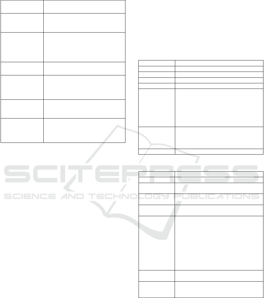
Table 1: Examples of requirements change impact.
Requirement
change
Impact on communication
diagrams
Add an actor
An object corresponding to the added
actor should be added to the
communication diagram.
Delete an actor
Objects corresponding to the deleted
actor should be deleted from the
communication diagram correspond-ding
to use cases associated to the deleted
actor.
Add a use case
A communication diagram must be
added.
Add an action in a
use case
A message must be added to the
communication diagram (from the object
(O1) to the object (O2), this information
can be extracted from the action).
Delete a use case
The Communication diagram
corresponding to the deleted Use Case
must be deleted.
Delete an action
from a use case
The messages corresponding to the
deleted action (retrieved with the cosine
similarity) must be deleted in the
communication diagram.
4 EXAMPLE
To illustrate our DTD-based traceability and its use
for requirement change impact analysis, let us
consider the online shopping system example
(Kollár et al., 2011). The use case diagram
comprises, essentially, four use cases (Figure 2):
Browse/search, manage shopping cart and place
order. The “manage shopping cart” and the “Place
order” UC textual descriptions are presented
respectively in Table 2 and Table 3.
Now, consider that we have two new
requirements: 1) the customer will be required to
add the order state in the Order Dialog. The order
state has an enumeration type and can be new,
packed, dispatched, delivered or closed. 2) The
payment method is deleted. In the following, we
identify the impact of these two new requirements
on the class and communication diagrams.
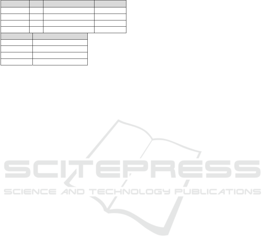
The communication diagrams corresponding to
these use cases are presented respectively in Figure
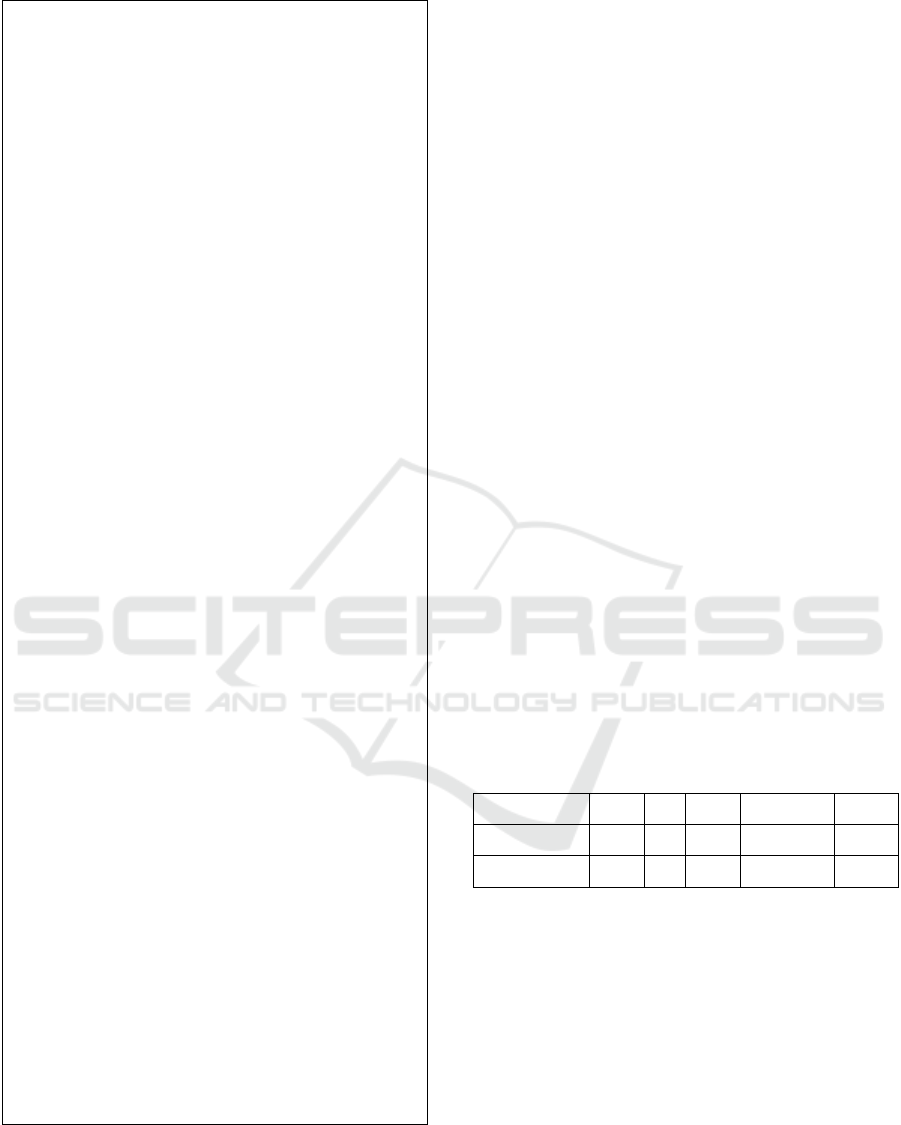
3 and Figure 4. Finally, the class diagram CD of this
example is presented in Figure 5.
The first step of our approach consists in
transforming the UC1, UC2, C
L
D1, C
L
D2 and the
class diagram into XMLs in order to integrate them
into a single XML document based on the DTD
integration. To compute the correspondence between
actions and messages in our example, the queries are
the list of messages and the documents are the list of
actions in a use case. For instance, the Tables 4 and
5 present respectively the use case description
“Place Order” and the messages in the communica
tion diagram of the use case “Place Order”. To find
the traceability between them, we use the cosine
similarity.
Table 2: The use case “Manage shopping cart”
description.
Use case Manage shopping cart
Actor Customer
Precondition The customer must be logged in
PostCondition Nothing
Extension Point Nothing
Normal
Scenario
<include>UC “Browse/search”<include>
NSa1: The customer picks up one or more
products from the list.
NSa2: The customer clicks the "Show
Shopping Cart" button.
NSa3: The customer adds products to or
removes products from the shopping cart.
Alternatives
Scenario
<The customer changes the amount of the
products, restart from2>
AS1a1: The system re-calculates the total
price in this case
Error Scenario None
Table 3: The use case “Place Order” description.
Use case Place Orde
r
Actor Customer
Precondition
The customer’s shopping cart contains at
least one item.
PostCondition
The system saves the new order and
performs further processing on it.
Extension
Point
Nothing
Normal
Scenario
NSa1: The customer selects one or more
items from the shopping cart
NSa2: The customer clicks the "Buy" button
NSa3: The customer fills in the required
personal data (name, phone number, email,
shipping address, billing address, etc.) on the
"Order" dialog>.
NSa4: The customer chooses the payment
method.
NSa5: The customer cancels the order.
Alternatives
Scenario
Nothing
Error Scenario
<The system cannot save the order due to a
database failure>
ES1a1: The custome
r
cannot load products.
A New Approach for Traceability between UML Models
135
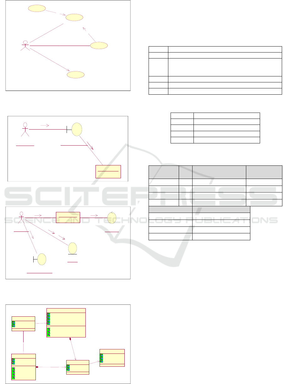
Figure 2: Main Use case diagram for the online shopping
system.
Figure 3: The communication diagram of the UC1
“Manage shopping card”.
Figure 4: The communication diagram of the UC2 “Place
Order”.
Figure 5: The Online shopping system class diagram.
Firstly, we calculate the weight W for each pair
(qi, dj) and the maximum value indicate that this
query (message) corresponds to this document
(action).
Table 4: The List of actions in the “PlaceOrder” UC.
NSa1 selects one or more items from the shopping car
t
NSa2 The customer clicks the "Buy" button
NSa3 fills in the required personal data (name, phone
number, email, shipping address, billing address,
etc.) on the "Order" dialog
NSa4 chooses the payment method
NSa5 cancel the orde
r
ESa1 cannot load products
Table 5: The list of messages in the C
L
D “Place Order”.
M1 Select(items)
M2 Click "Buy" button()
M3 n details()
M4 Pay(payment method)
M5 Pay()
q1: “select” “items”
d1: “selects” “items” “shopping” “cart”
d1 Tf Idf=log(m/d(i)) Weight (W)
selects 1 Log(6/1)=0.77815 0.77815
items 1 Lo
g(
6/1
)
=0.77815 0.77815
sho
pp
in
g
1Lo
g(
6/1
)
=0.77815 0.77815
cart 1 Lo
g(
6/1
)
=0.77815 0.77815
q1 Weight (W)
selects 1
items 1
sho
pp
in
g
0
cart 0
SIM(d1, q1)= W
d1,selects
*W
q1,selects
+W
d1,items
* W
q1,items
+
W
d1,shopping
*W
q1,shopping
+ W
d1,card
*W
q1,card
=1*0.77815+1*0.77815+0*0.77815+0*0.77815
=1.556302
This value is not normalized, for this reason we
calculate the cosine value between d1 and q1.
Σ(Wi1, W1j)= 1.556302
ΣWi1
2
=2.422069
ΣW1j
2
=2
Cos()= 1.556302/√2.422069∗2= 0.70
We note that the cosine value is close to the used
threshold (0.7). In fact, we assume that a similarity
value greater than or equal to 0.7 indicates a
similarity between an action and a message. Thus,
we deduce that q
1
(the message “select(Items)”) may
correspond to d1 (the action “select items from
shopping cart”).
Manage shopping cart
Browse/Search
Customer
Place Order
View product details
<<include>>
<<extend>>
: Customer
: GUIsearchresult
1: SelectProduct
Shoppingcart
2: Add(item)
3: remove(item)
: Customer
ShoppingCart
1: Select(Item)
: checkout
2: click "Buy" Botton
: OrderDetailsForm
3: Fillin details
: Order
4: pay(paymentmethod)
5: pay()
Order
dateplaced : date
shippingadress : adress
totalvalue : money
paymenttype : paymentmethod
pay(paymentmethod)
pay()
fill in details()
Product
name : string
description : string
unitprice : money
Item
Quantity : int
subtotal : money
1..n1..n
1
0..1
1
0..1
Customer
birthday : date
discount : money
0..1
n
0..1
n
shoppingcart
totalvalue : money
cartId : int
checkout()
add(item)
remove(item)
clear()
0..n0..n
0..n0..n
ICSOFT 2017 - 12th International Conference on Software Technologies
136
q2: “Click” "Buy" “button”
d
1
: “selects” “items” “shopping” “cart”
d1 Tf Idf=log(m/d(i)) Weight (W)
selects 1 Lo
g(
6/1
)
=0.77815 0.77815
items 1 Lo
g(
6/1
)
=0.77815 0.77815
sho
pp
in
g
1 Lo
g(
6/1
)
=0.77815 0.77815
cart 1 Log(6/1)=0.77815 0.77815
q1
Weight (W)
selects 0
items 0
sho
pp
in
g
0
cart 0
SIM(d1, q2)= W
d1,selects
*W
q1,selects
+W
d1,items
* W
q1,items
+
W
d1,shopping
*W
q1,shopping
+ Wd1,cart*Wq1,cart
=0.77815*0+0.77815*0+0.77815*0+0.77815*0=0
We remark that, the cosine value is null, thus we
deduce that q
2
may not be d
1
.
After calculating each pair (qi, dj), a possible
correspondence between messages in C
L
D1 and
actions in UC1 is established. The correspondence
table is presented to the designer who has the choice
to retain or to modify it.
Based on this correspondence, a single DTD
integration instance that contains all information
about the use case, class and communication
diagram is determined. Figure 6 shows the XML
document that integrates the use case, class and
communication diagrams of our example.
The XML document shows the addition of a
relationship “messagelink” from the customer class
to the “pay(paymentmethod)” operation of the
“Order” class.
In order to illustrate the usefulness of the DTD
integration in the change impact management, let us
suppose that the designer wants to make the
following changes to the use case diagram presented
in Figure 2:
New Requirement 1: The system requires to add
the order state in addition to the personal data in the
“Order” dialog. The action NSa3 “fills in the
required personal data (name, phone number, email,
shipping address, billing address, etc.) on the
"Order" dialog must be updated. The message Link
in the DTD (Figure 6) “fill in details()” indicates
that the message corresponding to NSa3 (M3) in the
communication diagram must be also changed. In
addition, the “fill in details()” operation in the class
diagram must be updated.
New Requirement 2: the payment method
requirement is deleted as an example. That is, the
fourth action in the normal scenario of the use case
UC2 “place order” will be deleted. This UC2
change requires that the message in the
communication diagram “Place Order”
corresponding to UC2 have to be deleted. In the
DTD instantiation, the relationship messageLink
corresponding to this deleted message indicates that
the method corresponding to the deleted message is
“pay(paymentmethod)”. This method should be
deleted if it is not used by another communication
diagram.
5 EVALUATION
Our approach is supported by a tool named CQV-
UML Tool (a Consistency and Quality Verification
tool for UML diagrams). The functional architecture
of this tool is presented in our previous work
(Kchaou et al., 2015).
The performance of our CIA and management
method and its associated tool was proven by a
comparative evaluation and expertise-based
evaluation.
In the comparative evaluation, the data used are
extracted from an open source system JHotDraw
(Jhotdraw 7.4.1, 2007) which represents a Java GUI
framework for technical and structured Graphics.
For this evaluation, we took two JHotDraw versions
(Jhotdraw 7.4.1, 2007) (Jhotdraw 7.5.1, 2007) and
collected the list of changes introduced to the first
version to obtain the second one. To validate our
approach, we compared the diagrams obtained by
applying the changes identified by our method with
a later JHotDraw version.
In addition, we conducted an expertise-based
evaluation based on a comparison between UML
diagrams where the change impact was obtained by
applying our method and UML diagrams where the
impact was handled by experts. More specifically,
we presented a list of changes and a UML project
(Wautelet et al., 2003) to experts and they were
asked to return the impacted elements as well as the
corrected diagrams. The participating experts are
UML professionals and have years of experience
studying and developing UML projects.
For evaluation purposes, we adapted the
measures of recall and precision. In our experiment,
precision represents the number of correct impacted
elements detected by our tool among all the
impacted elements found by our tool, while recall
represents the number of correct impacted elements
detected by our tool among all the existing real
impacted elements.
A New Approach for Traceability between UML Models
137
<?xml version="1.0" encoding="UTF-8" ?>
<UMLclass>
<className>Customer</ClassName>
<ObjectName>customer</ObjectName>
<ListOfattributes>
<Attr N1>
<Name>Birthdate </name>
<Type>Date<\type>
<visibility>Private<\visibility>
<Attr N2>
<Name>discount </name>
<Type>money<\type>
<visibility>Private<\visibility>
<listofRelationship>
<Assoc>
<Name>is placed by</name>
<cardinality>0..1</cardinality>
<class-relation>Order</class-relation>
<messageLink>
<action/method-relation>
pay(paymentmethod)<\action/method-relation>
<messageNBR>M4<\messageNBR>
<scenario-actionnumber>NSa4<\scenario-
actionnumber>
<usecasename>PlaceOrder<\usecasename>
<collaborationname>placeOrder<\collaborationna
me>
<messageLink>
<action/method-relation> fill in details (dateplaced,
shipping address, totalvalue, payment type)
<\action/method-relation>
<messageNBR>M3<\messageNBR>
<scenario-actionnumber>NSa3<\scenario-
actionnumber>
<usecasename>PlaceOrder<\usecasename>
<collaborationname>placeOrder<\collaborationna
me>
<className>Order</ClassName>
<ObjectName>order</ObjectName>
<ListOfattributes>
<Attr N1>
<Name>dateplaced </name>
<Type>Date<\type>
<visibility>Private<\visibility>
…
<ListOfOperations>
<Oper OpN1>
<name>fill in details<\name>
<listofRelationship>
<Assoc>
<Name>Items</name>
<cardinality>0..*</cardinality>
<class-relation>Item</class-relation>
…
Figure 6: XML document: a part of the DTD instantiation
for the online shopping system.
Moreover, we count the number of True
Positives (TP), FalsePositives (FP), and False
Negatives (FN). False positives are impacted
elements wrongly identified. False negatives are
actual impacted elements that have not been detected
by our approach.
Table 7 shows the precision and recall for this
evaluation. The value of the precision, which is 0.82
in the comparative evaluation and 0.87 in the
expertise evaluation, is explained by the fact that we
found some false positive impacted elements (i.e.
incorrect detected impacted elements). Compared to
the true positives found by our method, the false
positives impacted elements are not significant.
Concerning the recall, whose value is 0.90 in the
comparative evaluation and 0.92 in the expertise
evaluation, indicates that we have also some false
negative impacted elements (i.e. true impacted
elements not detected). The false negatives can be
explained by the fact that our approach does not treat
the concept of abstract classes and interfaces.
The precision rates are lower than recall for two
reasons: The first reason is that our approach does
not treat abstract classes and interfaces which are
used widely in the JhotDraw Versions. This problem
could be solved and the results would be improved
thanks to the flexibility of our approach. The second
reason is the incoherencies in the naming
terminology used in the different diagrams. In fact,
the Carsid project (Wautelet et al., 2003), the
terminology used differs from one diagram to
another, which is misleading. This makes the
traceability very difficult and consequently the
change impact cannot be determined correctly.
Table 6: Evaluation results.
Evaluation TP FP FN Precision Recall
Comparative 78 16 8 0.82 0.90
Expertise 62 9 5 0.87 0.92
6 CONCLUSION
This paper first proposed a new approach for
structural and semantic traceability among UML
diagrams; second, it shows how this traceability can
be used to manage requirements change impact on
UML class and communication diagrams. The
traceability method adopts an information retrieval
technique for the semantic traceability and a DTD-
XML based technique to identify systematically all
elements within and inter diagrams that are impacted
by a requirement change.
ICSOFT 2017 - 12th International Conference on Software Technologies
138

We are currently extending the model
dependency graph to account for the remaining
UML diagrams. In addition, we are examining how
to exploit our change impact management approach
in a software cost estimation technique to predict the
effort needed for the correction of changes.
REFERENCES
Ali, M. Ben-Abdallah, H. Gargouri, F. 2005, Towards a
Validation Approach of UP Conceptual Models,
Proceeding of Consistency in Model Driven
Engineering in European Conference on Model
Driven Architecture - Foundations and Applications.
Arnold, R. S., Bohner, S. A., 1993. Impact Analysis -
Towards a Framework for Comparison”. Proceedings
of the Conference on Software Maintenance.
Arora, C. Sabetzadeh, M. Goknil, A. L. Briand, Zimmer
F., 2015. Change impact analysis for natural language
requirements: An NLP approach. IEEE 23rd
International Requirements Engineering Conference,
2015, pp. 6-15.
Briand, L. C. Labiche, Y. O'Sullivan, L. Impact Analysis
and Change Management of UML Models. In
Proceedings of the International Conference on
Software Maintenance, 2003, pp. 256-265.
Chechik, M. Lai, W. Nejati, S. Cabot, J. Diskin, Z.
Easterbrook, S. Sabetzadeh M. and Salay, R., 2009.
Relationship-based change propagation: A case study,
in Modeling in Software Engineering, ICSE
Workshop.
Chidamber, S. R., Kemerer, C. F., 1991. Towards a
metrics suite for object oriented design. In Conference
proceedings of Object-oriented programming systems,
languages, and applications.
Cockburn, A., 2001. Writing Effective Use Cases.
Addison-Wesley.
De Lucia, A. Fasano, F. Oliveto, R. Tortora. G., 2007.
Recovering traceability links in software artifact
management systems using information retrieval
methods”. ACM Transaction Software Engineering
and Methodologies.
Divya, K. S., Subha, R. Palaniswami. S., 2014. Similar
Words Identification Using Naive and TF-IDF
Method, International Journal of Information
Technology and Computer Science.
Göknil, A., Kurtev, I., Berg van den, K.G. 2008. Change
Impact Analysis based on Formalization of Trace
Relations for Requirements. In: ECMDA Traceability
Workshop.
Gotel, O., Huang, J. C., Hayes, J. H., Zisman, A., Egyed,
A., Grünbacher, P. Dekhtyar, A. Antoniol, G. Maletic,
J. Mäder, P., 2011. Traceability Fundamentals”.
Software and Systems Traceability.
Gupta, A. Tripathi, A. Kuswaha, D., 2015. Use Case
Based Approach to Analyze Software Change Impact
and Its Regression Test Effort Estimation, Advanced
Computer and Communication Engineering
Technology, Lecture Notes in Electrical Engineering.
Hewitt, J. Rilling, J., 2005. A light-weight proactive
software change impact analysis using use case maps,
in Proceedings of the IEEE International Workshop on
Software Evolvability.
Jhotdraw7.4.1’,http://www.randelshofer.ch/oop/jhotdraw/j
avadoc741/overview-summary.html, 2007.
Jhotdraw7.5.1’,http://www.randelshofer.ch/oop/jhotdraw/j
avadoc751/overview-summary.html, 2007.
Jacobson, I., Booch, G. Rumbaug, J. 1999. The Unified
Software Development Process, Adission Wesley.
Kchaou, D. Bouassida, N. Ben Abdallah. H. 2015. CQV-
UML Tool: a tool for managing the impact of change
on UML models, The 27th International Conference
on Software Engineering and Knowledge Engineering.
Keller, A., Demeyer, S., 2012. Change Impact Analysis for
UML Model Maintenance. Book chapter: Emerging
Technologies for the Evolution and Maintenance of
Software Models, IGI Global publisher.
Khurana, P., Tripathi, A., Kushwaha, D.S. 2013. Change
impact analysis and its regression test effort
estimation, Published in Advance Computing
Conference.
Kollár, L. Sterbinszky, N. 2011. Case study in system
development- Notes, http://www.tankonyvtar.hu/hu/
tartalom/tamop412A/20110103_07_case_study_in_sy
stem_development/2011-
0103_07_case_study_in_system_development.pdf.
Lallchandani, J.T. Mall, R., 2009. Static Slicing of UML
Architectural Models, Journal of object technology.
Lormans, M. Van Deursen, A., 2006. Can LSI help
reconstructing requirements traceability in design and
test? In Proceedings of 10th European Conference on
Software Maintenance and Reengineering.
Mens, T. 2005. Challenges in Software Evolution. 8th
International Workshop on Principles of Software
Evolution, IEEE CS Press.
Roques, P. 2003. UML, modéliser un site E-Commerce,
Edition Eyrolles.
Singhal, A. 2013. Modern Information Retrieval: A Brief
Overview. Bulletin of the IEEE Computer Society
Technical Committee on Data Engineering 24.
Tsiolakis, A., 2000. Consistency analysis of UML class
and sequence diagrams based on attributed Typed
graphs and their transformations, ETAPS workshop on
graph transformation systems.
Visual Paradigm International, 2014. http://www.visual-
paradigm.com/support/documents/vpumluserguide/44
7/449/20237_analyzingamo.html
Wautelet, I. Louvigny, L. Kolp, M. 2003. Le Unified
Process comme méthodologie de gestion de projet
informatique», Mémoire-projet, Université Catholique
de Louvain.
A New Approach for Traceability between UML Models
139
