Efficient Scenario Verification of Proximity-based Federations among
Smart Objects through Symbolic Model Checking
Reona Minoda and Shin-ichi Minato
Graduate School of Information Science and Technology, Hokkaido University, Sapporo, Japan
Keywords:
Ubiquitous Computing, Catalytic Reaction Network, Formal Verification, Symbolic Model Checking, Smart
Object.
Abstract:
Verification of ubiquitous computing (UC) scenarios enables us to detect design-related faults of UC appli-
cations before we actually implement them. In this paper, we propose a verification framework of context
catalytic reaction network (CCRN), which is a description model of UC scenarios, as a new application field
of symbolic model checking. To do so, we illustrate a method how to transform a scenario written in CCRN
into a symbolic model checking problem. We also show experimentally that our framework makes it possible
to verify large scale UC scenarios which could not be verified in realistic time by our previous method. Addi-
tionally, we show experimentally the usefulness of fault detections using bounded model checking in the same
framework.
1 INTRODUCTION
Today, we are surrounded with various devices with
computation and communication capabilities. In
this paper, we call these devices “smart objects
(SO)”. SOs include personal computers (PCs), mobile
phones, sensor devices, embedded computers and ra-
dio frequency identifier (RFID) tags. But we can also
treat physical things like foods, medicine bottles and
cups as SOs by embedding RFID tags in those. Here
we use the term federation to denote the definition
and execution of interoperation among resources that
accessible either through the Internet or through peer-
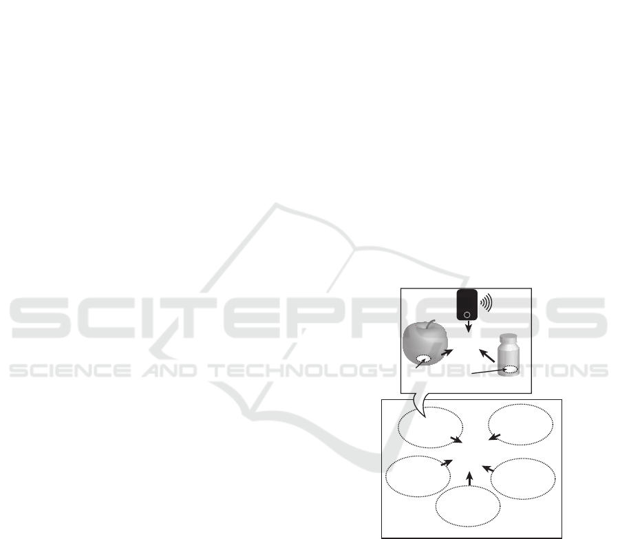
to-peer ad hoc communication. For example, let us
consider that there are a phone, a medicine bottle and
food, and RFID tags are embedded in a medicine bot-
tle and food. Imagine that this food and the medicine
have a harmful effect when eaten together. If all these
things are close to each other, a phone rings to in-
form a user to warn not eat them together. This phe-
nomenon is a federation. Indeed, we can also consider
federations related to other SOs and these federation
may be involved in each other. We call these fed-
eration “ubiquitous computing application scenarios
(UC scenario)” (see Fig.1).
Yuzuru Tanaka pointed out that the importance of
UC scenario analyses and discussions because this
liberates us from stereotyped UC scenarios such as
“location transparent service continuance” (i.e., a
Federation
...
Federation
Federation
Federation
Federation
Involved in
Each Other
Other
Federations
Embeded Chips
(e.g., RFID tags, etc.)
Close to
Each
Other
Ring!
Ring!
Food
Phone
Medicine
Bottle
Figure 1: Example of Ubiquitous Computing Application
Scenario.
user can use a service wherever the user goes) and
“context-aware service provision” (i.e., a user can use
different kinds of services depending on where the
user is) (Tanaka, 2010). Julia and Tanaka proposed
catalytic reaction network as a description model of
UC scenario (Julia and Tanaka, 2016).
In our previous work, we extended a catalytic re-
action network model to context catalytic reaction
network (CCRN) by adding a discrete structure called
“segment graph”. Using a CCRN model, we formal-
ized a UC scenario verification problem and proposed
Minoda, R. and Minato, S-i.
Efficient Scenario Verification of Proximity-based Federations among Smart Objects through Symbolic Model Checking.
DOI: 10.5220/0006429900130021
In Proceedings of the 7th International Joint Conference on Pervasive and Embedded Computing and Communication Systems (PECCS 2017), pages 13-21
ISBN: 978-989-758-266-0
Copyright © 2017 by SCITEPRESS – Science and Technology Publications, Lda. All rights reserved
13

a method to reduce UC scenario verification problems
to model checking problems (Minoda et al., 2016).
This method enabled us to discuss the properties of
UC scenarios. These properties are included as fol-
lows.
• Determining whether a property described in a
linear temporal logic (LTL) specification (e.g.,
a particular federation finally occurs after some
conditions) is satisfied or not in the given UC sce-
nario described by CCRN.
• Showing a counterexample if there are any cases
violating the properties described above.
Most important aspect of this kind of verification is
that these discussions about properties of a given UC
scenario can be done in the step of the design before
the implementation steps which may incur additional
costs.
However, this reduction method was a kind of
naive approach so there were challenges related to the
scalability during the verification. In this paper, we
propose a verification method using symbolic model
checking to improve the scalability. Symbolic model
checking is a one of model checking technique to ver-
ify very large scale of state transition systems (Burch
et al., 1992). We show the method how to take advan-
tage of symbolic model checking techniques when we
reduce UC scenario verification problems to model
checking problems. We also show experimentally that
our method can verify larger UC scenario verification
problems compared to our previous naive approach.
As a result, this method enables us to discuss more
practical UC scenario verification problems.
Additionally, if we establish a reduction method
using a symbolic model checking approach, we can
also take advantage of bounded model checking in
the same framework (Biere et al., 1999). Bounded
model checking can detect counterexamples from a
given model checking problem faster than symbolic
model checking in most cases (Note that bounded
model checking is not good at proving that there is
no counterexample of a given model checking prob-
lem). Bounded model checking is widely used for the
counterexample detection from model checking prob-
lems. In this paper, we also evaluate experimentally
how practical is bounded model checking for UC sce-
nario verification problems.
The rest of this paper is organized as follows. The
rest of this section introduces related works of our re-
search. Section 2 provides preliminaries of this pa-
per, such as basic definitions and notations including
CCRN, symbolic model checking and bounded model
checking. Using them, we propose the verification
method of CCRN using symbolic model checking in
section 3. In section 4, we evaluate our verification
method experimentally by using both symbolic model
checking and bounded model checking. Finally, we
conclude our contributions in section 5.
1.1 Related Works
In this section, we enumerate related researches in the
field of ubiquitous computing.
Formal Verification of Cyber Physical Systems.
Similarly to ubiquitous computing, a lot of
devices such as sensors measure physical
phenomena such as temperature, humidity, ac-
celeration and so on, while actuators manipulate
the physical world, like in automated robots.
The combination of an electronic system with a
physical process is called cyber physical system
(CPS). In the field of CPS, Drechsler and K
¨
uhne
use timed automata (Alur and Dill, 1994) as a
state transition model to conduct formal verifica-
tions of given systems’ properties (Drechsler and
K
¨
uhne, 2015).
Context Inconsistency Detection. In the field of
ambient computing, Xu and Cheung propose a
method of context inconsistency detection (Xu
and Cheung, 2005). This method detects incon-
sistencies from a series of gathered events such as
“a user entered a room” and “the temperature of
room is 30
◦
C” by logical deduction. Unlike a for-
mal verification, this method can be applied only
after the system begins to work. Instead, a formal
verification can find the failed cases from a given
system in advance.
2 PRELIMINARIES
In this section, we give definitions and notations
which is necessary for this paper.
2.1 Basic Definitions and Notation
Let X and Y be any two sets, we use X ∪Y , X ∩Y and
X \Y to denote the union, intersection and difference
of X and Y respectively. For a set X , we denote its
power set (i.e., all subsets) by 2
X
and its cardinality
by |X|. For a family M of sets (i.e., a set of sets), we
denote the union and the intersection of all sets in M
by
S
M and
T
M respectively.
2.2 Catalytic Reaction Network
A catalytic reaction network is originally proposed
by Stuart Kauffman in the field of biology to ana-
lyze protein metabolism (Kauffman, 2002). Based on
PEC 2017 - International Conference on Pervasive and Embedded Computing
14
Gate
Headset
Phone
IC card
Scope of
(iii) Phone and headset
are federated (denoted by ).
expressed as
makes and federated.
(ii)
(i) A user enters into
the scope of .
(This action is triggered by .)
Figure 2: Example of a Catalytic Reaction.
this model, Tanaka applied it to the field of ubiquitous
computing as the way to describe an application sce-
nario involving mutually related multiple federations
among SOs (Tanaka, 2010). In this paper, we mean
the latter by the term “catalytic reaction network”.
A catalytic reaction network is a set of catalytic
reactions. Each catalytic reaction takes input materi-
als and transforms them into output materials. And
each catalytic reaction has a catalyst which is called
context. It may be also possible to include a cata-
lyst in input materials. We call this kind of catalyst
stimulus. A catalytic reaction is occurred when all re-
quired SOs are in the proximity of each other. We use
the term “scope” to denote the inside of the proximity
area (we assume a range of Wi-Fi radiowave, and so
on). The scope of a SO o is represented as a set of SOs
which are accessible from the SO o. We assume that
only the scopes of contexts are considered instead. In
other words, we consider that the catalytic reaction is
occurred if all required SOs just enter into the scope
of the corresponding context.
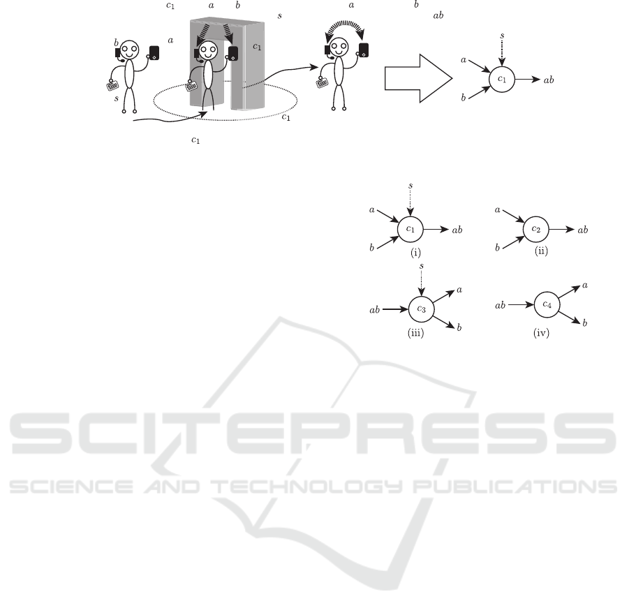
Figure 2 shows an example of single catalytic re-
action. In this example, there is a gate c
1
regarded as
a context and a user has three SOs i.e., a phone a, a
headset b and an IC card s. If the user enters into the
scope of c
1
, c
1
makes a and b federated. This action
is triggered by s. After that, phone a and headset b
are federated. We denote federated SOs such as a and
b by a concatenation of a and b, i.e., ab. During this
process, c
1
and s work as catalysts. In particular, s is
a stimulus in this reaction. We express this reaction
as the right hand side diagram of Fig. 2.
In catalytic reaction networks, there are four types
of catalytic reactions as we show in Fig. 3. We cate-
gorize these four types of reactions into two groups.
One group is the composition reaction group (Fig. 3
(i) and (ii) ), the other group is the decomposition re-
action group (i.e., Fig. 3 (iii) and (iv) ). A catalytic
reaction of Fig. 2 is a type (i) catalytic reaction. We
also consider the catalytic reaction without a stimulus
such as Fig. 3 (ii). In type (ii), if a user who has SO a
and SO b enters into the scope of context c
2
, c
2
makes
a and b federated without a stimulus. In a similar way,
Figure 3: Four Types of a Catalytic Reactions.
we consider the decomposition reactions such as Fig.
3 (iii) and (iv). In type (iii), if a user who has two
SOs that are federated into ab enters into the scope of
context c
3
, c
3
decomposes these SOs ab into a and b
triggered by SO s. Type (iv) is a decomposition reac-
tion without a stimulus.
The output SO of a reaction may promote other re-
actions as a stimulus or become an input SO of other
reactions. In this way, catalytic reactions form a net-
work of reactions.
Now we define a catalytic reaction network for-
mally. First, let O be a set of SOs, we give a definition
of a federated SO o
f
by o
f
∈ 2
O
\{
/
0} where |o
f
| > 1.
If |o
f
| = 1, we treat o
f
as a single SO. Next, we define
a catalytic reaction as follows:
Definition 1 (Catalytic Reaction). Let O and C be a
set of SOs and a set of contexts respectively, a cat-
alytic reaction is defined as a tuple (c, M, N) where
• c ∈ C, M ⊆ 2
O
\
/
0, N ⊆ 2
O
\
/
0
• ∀o
f
∀o
0
f
∈ M.(o
f
6= o
0
f
→ o
f
∩ o
0
f
=
/
0)
• ∀o
f
∀o
0
f
∈ N.(o
f
6= o
0
f
→ o
f
∩ o
0
f
=
/
0)
•
S
M =
S
N, and
• (|M ∩ N| + 1 = |N|, |M| > |N|) ∨
(|M ∩ N| + 1 = |M|, |M| < |N|) (∗)
The former of the last condition (signed by (∗))
and the latter of the last condition correspond to a nec-
essary condition for composition reaction and decom-
position reaction respectively.
We give some examples of catalytic reac-
tions. Given C = {c
1
, c
3
}, O = {a, b, s}, a cat-
Efficient Scenario Verification of Proximity-based Federations among Smart Objects through Symbolic Model Checking
15
Scope of
Scope of
Context
Context
A user can walk around a path .
Given Situation
Corresponding Segment Graph
Scope of
Scope of
Figure 4: Example of Segment Graph.
alytic reaction of Fig. 3 (i) and (iii) can be
defined by (c
1
, {{a}, {b}, {s}},{{a, b}, {s}}) and
(c
3
, {{a, b}, {s}},{{a}, {b}, {s}}) respectively.
Finally, a catalytic reaction network is defined as
follows:
Definition 2 (Catalytic Reaction Network). A cat-
alytic reaction network is a set of catalytic reactions.
2.3 Context Catalytic Reaction Network
This section describes a segment graph and a CCRN.
2.3.1 Segment Graph
As we discussed in previous section, a catalytic re-
action is occurred when required SOs enter into the
scope of the corresponding context. To analyze the
property of a given catalytic reaction network as a
state transition system, it is necessary to formalize the
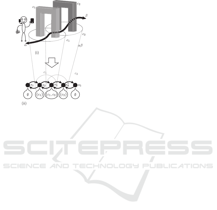
movement of SOs. For example, in Fig. 4 (i), there are
contexts c
1
and c
2
and these scopes have an overlap.
A user can walk around the path αβ shown in Fig.
4 (i). This situation can be represented as a segment
graph shown in Fig. 4 (ii). We consider that the user
walk around this segment graph and the user is always
located at one of the nodes of this segment graph.
Each node of a segment graph has a corresponding
set of scopes of contexts. In this way, the given sit-
uation like Fig. 4 (i) including overlaps of scopes of
contexts can be represented as a discrete structure.
Now we define a segment graph as follows.
Definition 3 (Segment Graph). Let C be a set of con-
texts, a segment graph G is a tuple (S, E, F), where
• S is a finite set of segments,
• E ⊆ S × S is a set of directed edges between two
segments, and
• F : S → 2
C
is a function returning scopes of con-
texts at corresponding segments.
2.3.2 Context Catalytic Reaction Network
A context catalytic reaction network (CCRN) is a dis-
crete structure of a situation involving SOs in a cat-
alytic reaction network. A CCRN is defined as a con-
bination of a segment graph and a catalytic reaction
network.
Definition 4 (Context Catalytic Reaction Network).
A context catalytic reaction network (CCRN) is a tu-
ple (O,C, R,G, L
FIX
, l
0
), where
• O is a set of smart objects,
• C is a set of contexts,
• R is a set of catalytic reactions,
• G is a segment graph (S, E, F),
• L
FIX
⊆ O × S is the locations of fixed SOs, and
• l
0
∈ S is the initial segment locating mobile SOs
(mobile SOs can be represented as O \ {o ∈ O |
∃s ∈ S.((o, s) ∈ L
FIX
)}).
2.4 Model Checking
A model checking is a method to verify a property
of a state transition system. It has been often used in
various fields, which ranges from electronic-circuit-
design verification (Burch et al., 1990) to secure-
network-protocol (e.g., Secure Sockets Layer (SSL)
protocol) design verification (Mitchell et al., 1998).
In the model checking, it is typically assumed to use
a Kripke structure as a state transition system. The
property of a Kripke structure is described by a modal
logic. There are two kind of commonly used modal
logics such as linear temporal logic (LTL) and com-
putational tree logic (CTL). In this paper, we use LTL
to describe the property of the Kripke structure.
2.4.1 Kripke Structure
Before we look on the detail of a model checking,
we give the definition of a Kripke structure (Kripke,
1963) which is necessary for a modal logic and a
model checking.
Definition 5 (Kripke Structure). Let AP be a set of
atomic propositions, a Kripke structrue M is a tuple
(S, I, R, L), where
PEC 2017 - International Conference on Pervasive and Embedded Computing
16

• S is a finite set of states,
• I ⊆ S is a set of initial states,
• R ⊆ S ×S is a set of transition relation such that R
is left-total, i.e., ∀s ∈ S, ∃s
0
∈ S such that (s, s
0
) ∈
R, and
• L : S → 2
AP
is a labeling function.
2.4.2 Linear Temporal Logic
Linear temporal logic (LTL) is one of the most well-
known modal logic. LTL was first proposed for the
formal verification of computer programs by Amir
Pnueil in 1977 (Pnueli, 1977). First, we give a def-
inition of LTL syntax.
Definition 6 (Linear Temporal Logic Syntax). Let
AP be a set of atomic propositions, a linear tempo-
ral logic formula φ is defined by the following syntax
recursively.
φ ::= > | ⊥ | p | ¬φ | φ∨φ | X φ | G φ | F φ | φ U φ (1)
where p ∈ AP.
These right-hand terms denote true, false, p, nega-
tion, disjunction, next time, always, eventually and
until respectively.
Next, we define a transition path π of a Kripke
structure M.
Definition 7 (Transition Path). Let M be a Kripke
structure, π = (π
0
, π
1
, π
2
, . . .) is a transition path
in M if it respects M’s transition relation, i.e.,
∀i.(π
i
, π
i+1
) ∈ R. π
i
denotes π’s ith suffix, i.e., π
i
=
(π
i
, π
i+1
, π
i+2
, . . .).
Also it can be shown that
(π
i
)
j
= (π
i
, π
i+1
, π
i+2
, . . .)
j
= (π
i+ j
, π
i+ j+1
, π
i+ j+2
, . . .)
= π
i+ j
. (2)
Now we focus on the semantics of linear temporal
logic. First, we define the binary satisfaction relation,
denoted by |=, for LTL formulae. This satisfaction is
with respect to a pair – hM, πi, a Kripke structure and
a transition path. Then we enumerate LTL semantics
as follows:
• M, π |= > (true is always satisfied)
• M, π 6|= ⊥ (false is never satisfied)
• (M, π |= p) iff (p ∈ L(π
0
)) (atomic propositions
are satisfied when they are members of the path’s
first element’s labels)
And there are two LTL semantics of boolean combi-
nations as follows:
• (M, π |= ¬φ) iff (M, π 6|= φ)
• (M, π |= φ ∨ ψ) iff [(M, π |= φ)∨ (M, π |= ψ)]
And there are four LTL semantics of temporal opera-
tors as follows:
• (M, π |= X φ) iff (M, π
1
|= φ)
• (M, π |= F φ) iff
∃i.(M, π
i
|= φ)
• (M, π |= G φ) iff
∀i.(M, π
i
|= φ)
• (M, π |= φ U ψ) iff
(∃i.(M, π
i
|= ψ)) ∧ (∀ j < i.(M, π
j
|= φ))
2.4.3 Model Checking Problem
Intuitively saying, a model checking problem is to
judge whether a given Kripke structure M satisfies a
given property described in a modal logic formula φ.
A model checking problem is formally stated as fol-
lows.
Definition 8 (Model Checking Problem). Given a de-
sired property described by a modal logic formula φ
(in this paper, we use LTL) and a Kripke structure
M, a model checking problem is a decision problem
whether the following formula
∀π.(M, π |= φ) (3)
is satisfied or not. Note that a set {π | (M, π 6|= φ)} is
particularly called a set of counterexamples.
It is known that a model checking problem can be
reduced to a graph search if M has finite states.
There are several implementations of the model
checking verifier such as Simple Promela INterpreter
(SPIN) (Holzmann, 1997) and Label Transition
System Analyzer (LTSA) (Magee and Kramer, 1999).
2.4.4 Symbolic Model Checking
If the number of states in a given Kripke structure
M becomes bigger, the cost of “a graph search” in-
creases exponentially. To ease this problem, McMil-
lan et al. proposed symbolic model checking (Burch
et al., 1992). Symbolic model checking does not
hold explicitly states and transitions of a given Kripke
structure. Instead, it holds symbolically them as
Boolean formulae. It uses a binary decision diagram
(BDD) (Bryant, 1986) to store these Boolean formu-
lae. By this, it can verify efficiently a very large
Kripke structure such as 10
20
states and more.
In symbolic model checking, a set of states S
in a Kripke structure are represented as a following
Boolean function S(s) using a variable vector s.
S(s) =
(
True if s ∈ S
False otherwise
(4)
Efficient Scenario Verification of Proximity-based Federations among Smart Objects through Symbolic Model Checking
17

A set of initial states I ⊆ S also can be represented as
the same way. To represent transition from s ∈ S to
s
0
∈ S and its relations R ⊆ S × S, we use following
Boolean function T (s,s
0
).
T (s,s
0
) =
(
True if (s, s
0
) ∈ R
False otherwise
(5)
S(s) and T (s, s
0
) are actually held as BDDs in
symbolic model checking verifiers but we do not need
give BDDs to them directly. Instead, we give a vari-
able vector s representing states and Boolean func-
tions of S(s), I(s) and T (s, s
0
) to symbolic model
checking verifiers. One of famous implementations
of symbolic model checking is New Symbolic Model
Verifier version 2 (NuSMV2) (Cimatti et al., 2002).
2.4.5 Bounded Model Checking
Using above the variable vector s, Boolean functions
I(s) and T (s,s
0
), we can introduce bounded model
checking proposed by Biere et al. (Biere et al., 1999).
Bounded model checking is a kind of symbolic model
checking. Most remarkable thing is that it reduces
a model checking problem to a satisfiability problem
(SAT) which can be solved by various SAT solvers. In
recent days, a lot of SAT solvers are developed day by
day and these SAT solvers’ capability of solving SATs
increases very rapidly (Jarvisalo et al., 2012). Basi-
cally, to conduct bounded model checking, we judge
whether following Boolean function
I(s
0
) ∧
k−1
^
i=0
T (s
i
, s
i+1
)
!
∧ ¬p(s
0
, . . ., s
k
) (6)
is satisfiable or not. Note that Boolean function
p(s
0
, . . ., s
k
) is generated from a given LTL formula
φ by a bounded model checking method, and k is
the number of steps from initial states to verify a
property φ. This is a reason why this method is
called “bounded” model checking. If above Boolean
formula is satisfiable, the corresponding assignments
s
0
, . . ., s
k
represents a counterexample of φ. Other-
wise it means that there is no counterexample of φ
at least k-steps from initial states. Most of modern
SAT solvers are good at finding satisfiable assign-
ments of a given Boolean function rather than proving
non-existence of satisfiable assignments of the func-
tion. This means that bounded model checking is suit-
able for detecting counterexamples of LTL formulae.
In fact, NuSMV2 can also conduct bounded model
checking.
3 CCRN VERIFICATION
THROUGH SYMBOLIC MODEL
CHECKING
In this section, we propose a method of reducing
a CCRN verification to a symbolic model checking
problem. Concretely, we propose a way to transform a
CCRN (O,C, R,(S, E, F), L
FIX
, l
0
) into a variable vec-
tor s and Boolean functions S(s), I(s) and T (s).
There are two types of states in a CCRN
(O,C, R,(S, E, F), L
FIX
, l
0
). One is a state of mobile
SOs’ location. A set of mobile SOs O
MOB
are de-
fined as O \ {o ∈ O | ∃s ∈ S.((o, s) ∈ L
FIX
}. O
MOB
are
carried together by a user and are located at segment
s ∈ S, so this kind of states has |S| states. The other
type of states is a state of existence of federated SOs
o
f
. Federated SOs o
f
are defined as o
f
∈ 2
O
\ {}, so
2
|O|
− 1 kinds of o
f
can be considered. As a result,
there are 2
2
|O|
−1
states of 2
|O|
− 1 kinds of o
f
s’ ex-
istence. Therefore, there are |S| × 2
2
|O|
−1
states of a
given CCRN if we count its states explicitly. Now we
deal with this large states by introducing a symbolic
approach for efficient verification.
At first, we define a variable vector s representing
states. Considering the above discussion, we repre-
sent a state that mobile SOs O
MOB
are located at seg-
ment s ∈ S as “segment = s”, and a state that federated
SOs o
f
are existing as “fed(o
f
) = True” respectively.
Using those, we define a variable vector s as follows.
s = (segment, fed(o
f
), fed(o
f
0
), ·· ·
| {z }
2
|O|
−1
) (7)
In this paper, Boolean function S(s) representing all
possible states are defined as a Boolean function that
returns True for all s. Instead, we define appropriate
T (s,s
0
) in the rest of this section. Boolean function
I(s) representing initial states are defined as follows.
I(s) =(segment = l
0
)
∧
^
o
f
∈2
O
\{},|o
f
|=1
fed(o
f
) = True
∧
^
o
f
∈2
O
\{},|o
f
|>1
fed(o
f
) = False
(8)
Next, we define T (s,s
0
). To make the representa-
tion of T (s, s
0
) simple, we define auxiliary variables.
We define transitions S
e
that mobile SOs S
MOB
move
from segment s to segment s
0
along the edge e of a
given segment graph as follows.
S
e
, (segment = s) ∧(segment
0
= s
0
) (9)
PEC 2017 - International Conference on Pervasive and Embedded Computing
18
(Room 1)
(Room 2)
Exhibit
Exhibit
Headset
Phone
Ticket
At first, a user locates at .
Catalytic Reactions:
, and are mobile SOs.
is fixed SOs located at .
: a scope of a context.
Figure 5: Museum Example of CCRN.
We also consider transitions of changing the state of
federated SOs’ existence. In the case of CCRN, this
kind of state changes are occurred when catalytic re-
actions are occurred. We define transitions R
/
0
that no
catalytic reaction was occurred as follows.
R
/
0
,
^
o
f
∈2
O
\{}
fed(o
f
) = fed
0
(o
f
)
(10)
Furthermore, we define transitions R
r
that catalytic re-
action r = (c, M, N) was occurred as follows.
R
r
,
^
o
f
∈N
fed
0
(o
f
) = True
∧
^
o
f
∈M
fed
0
(o
f
) = False
∧
^
o
f
∈(2
O
\{})\(M∪N)
fed(o
f
) = fed
0
(o
f
)
(11)
And we define the condition RC
r
which is necessary
for catalytic reaction r as follows.
RC
r
,
^
o
f
∈M
(fed(o
f
) = True) (12)
A set of catalytic reactions R
app
(e) that are occurred
when mobile SOs O
MOB
move from segment s ∈ S to
segment s
0
∈ S along the edge e in a given segment
graph, is defined as follows.
R
app
(e) , {(c, M, N) ∈ R | c ∈ F(s
0
), O(c) ⊇
[
M} where
O(c ∈ C) = O
MOB
∪ {o ∈ O | ∃s
00
∈ S.(c ∈ F(s
00
), (o, s
00
) ∈ L
FIX
} (13)
Then, we define transition relation T
e
of each edge
e ∈ E of a given segment graph as follows.
T
e
,
S
e
∧ R
/
0
if R
app
(e) =
/
0
_
r∈R
app(e)
S
e
∧ RC
r
∧ R
r
∨
S
e
∧ ¬
_
r∈R
app(e)
RC
r
∧ R
/
0
otherwise
(14)
Finally, using the definition of T
e
, we define T (s, s
0
)
as follows.
T (s,s
0
) =
_
e∈E
T
e
(15)
4 EXPERIMENTS AND
DISCUSSION
In this section, we report results of two kinds of ex-
periments. First one is intended to show the scalabil-
ity of the proposed method. Second one is aimed to
show the usefulness of bounded model checking.
4.1 Scalability of CCRN Verification
through Symbolic Model Checking
In this experiment, we evaluated the scalability of
our method. To conduct the experiment, we used a
CCRN such as Fig.5. Left hand side of Fig.5 repre-
sents the corresponding segment graph of the CCRN.
This CCRN assumes an UC scenario of a museum
that has n rooms and each room i has a exhibit d
(i)
.
We define reactions c
1
and c
2
to make a phone a and
a headset b federated for a museum guide service and
we also define reactions c
(i)
3
and c
(i)
4
to provide an ex-
planation of exhibit d
(i)
to the user in corresponding
room i. Directed edges (s
(i)
6
, s
(i+1)
2
) and (s
(i+1)
6
, s
(i)
2
) of
the segment graph represent stairs connected between
room i and room i + 1. We set properties of these
cases by following LTL formula.
G(segment = s
(1)
1
→ F(segment = s
(n)
4
→ fed({a, b, d
(n)
}) = True) )
(16)
This formula means that if the user once enters the
museum, the exhibit explanation of the highest floor
Efficient Scenario Verification of Proximity-based Federations among Smart Objects through Symbolic Model Checking
19
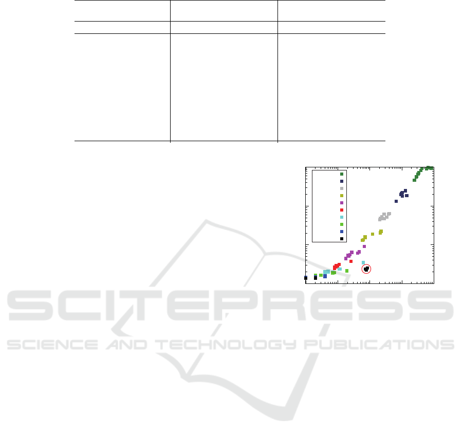
Table 1: Experiment Results of The Scalability Evaluation.
Problem Instance
Naive Method
(Minoda et al., 2016) Proposal Method
n |O| |C| |S| CPU (s) MEM (MB) CPU (s) MEM (MB)
1 4 4 6 0.01 13.81 0.01 13.41
2 5 6 11 0.04 16.50 0.02 15.24
3 6 8 16 0.41 48.46 0.04 19.61
4 7 10 21 8.69 656.75 0.09 31.64
5 8 12 26 273.56 13,088.76 0.24 67.85
6 9 14 31 N/A MEM. Out 0.78 188.54
7 10 16 36 — — 2.85 636.56
8 11 18 41 — — 10.93 2,349.27
9 12 20 46 — — 78.12 9,368.13
10 13 22 51 — — 455.73 13,075.79
11 14 24 56 — — N/A MEM. Out
Remarks: “MEM. Out” means that we abort the experiment due to the lack of memory.
is always provided to the user. And this museum ex-
ample satisfies this formula. So, in this case, we ver-
ified the CCRN to confirm this formula actually does
satisfy.
We conducted this experiment by using a Core i7
3820QM machine with 16GB memory. In this ex-
periment, we use NuSMV2 version 2.6.0 as a model
checking verifier. We also compared with our naive
method which is our previous work (Minoda et al.,
2016). The naive method enumerates all possible
states of a given CCRN explicitly. So even if we
use NuSMV2, this naive method do not take any ad-
vantage of symbolic model checking. Table. 1 indi-
cates the experiment results through the cases from
n = 1 to n = 11 The left-hand side, the middle and
the right-hand side of this table indicate the size of
model checking problems, the cost needed for solv-
ing them by our previous naive method and the cost
needed for solving them by our proposal method re-
spectively. On this machine used for this experiment,
the instance of n = 5 is a limit of our previous naive
method. However, our proposal method extended the
limit to n = 10. In the case of n = 10, there would
be about 2.78 × 10
2467
states if we enumerate those
states explicitly. It also can be said that our pro-
posed method reduced the double exponential scale of
problem into the single exponential scale of problem.
From these results, we illustrate that using symbolic
model checking enables us to verify more large scale
of UC scenarios in realistic time and costs.
4.2 Detecting Faults of CCRN through
Bounded Model Checking
We conducted another kind of experiment to show the
usefulness of bounded model checking. In this ex-
periment, we used the same example of the CCRN
as shown in Fig.5. However, to detect faults of the
given CCRN, we omitted randomly reactions c
(i)
3
and
10
100
1000
10000
0.01 0.1 1 10 100
MEM. Usage (MB)
CPU Time (sec)
n = 10
n = 9
n = 8
n = 7
n = 6
n = 5
n = 4
n = 3
n = 2
n = 1
Figure 6: Computational Costs for CCRN Fault Detection.
c
(i)
4
on purpose. By doing this, we generated differ-
ent 10 problem instances from each example of mu-
seum with n rooms through the cases from n = 1 to
n = 10. So, totally, we verified 100 problem instances
of “degraded” museum examples by bounded model
checking. We set properties of these cases by a LTL
formula as follows.
G
n
^
i=1
(¬(segment = s
(i)
4
) ∧ fed({a,b, d
(i)
}) = False)
∨ (segment = s
(i)
4
∧ fed({a, b, d
(i)
}) = True)
(17)
This means that all reactions for corresponding expla-
nation of exhibits in each room occurs properly. We
conducted this experiment by using the same machine
and same version of NuSMV2 as the scalability ex-
periment and we set the bound of verification k = 50.
In Fig.6, each dot’s color corresponds to the size
of the problem instance (i.e., the number of rooms)
and each dot’s coordinate indicates the computational
costs needed for the problem instance verification to
detect the faults. From this results, we can conclude
that most of cases are faster and less memory usage
than the cases of symbolic model checking when we
PEC 2017 - International Conference on Pervasive and Embedded Computing
20

are intended to detect faults of a given CCRN. For ex-
ample, there is a case of detecting a fault in 24.73 sec
from one of problem instances of n = 10. If we detect
a fault from this problem instance by using symbolic
model checking, it takes 318.87 sec.
Note that some cases of n = 1 enclosed with a cir-
cle in Fig.6 take more time and more memory space
because no reactions of these cases are omitted by
chance. An usual bounded model checking verifier
confirms the property inductively by changing the
bound through k = 1 to k = 50. The verifier aborts
the verification as soon as it detects any faults. How-
ever if there is no faults in cases which we remark
above, the verifier is forced to verify until k = 50 (in
this case of this experiment setting) and this causes
to take more time and more memory spaces. In other
words, we can expect that a bounded model checking
method detects faults very fast if they exists.
5 CONCLUSIONS
We proposed a method to reduce a CCRN verification
problem to a symbolic model checking problem. Our
proposal method enables us to verify more large scale
UC scenarios in realistic time and memory space.
To show that symbolic model checking is useful ap-
proach to verify UC scenarios, we conducted experi-
ments using a museum example of UC scenario as a
case study. Additionally, we also show that bounded
model checking is also useful approach especially to
detect faults of UC scenario. As our future work, we
continue to improve the scalability of our method. To
do so, we consider to reduce variables in variable vec-
tor s.
ACKNOWLEDGEMENTS
This work was partly supported by JSPS KAK-
ENHI (S) Grant Number 15H05711.
REFERENCES
Alur, R. and Dill, D. L. (1994). A theory of timed automata.
Theoretical Computer Science, 126(2):183–235.
Biere, A., Cimatti, A., Clarke, E., and Zhu, Y. (1999). Sym-
bolic model checking without BDDs. In Tools and
Algorithms for the Analysis and Constructions of Sys-
tems, number 97, pages 193–207.
Bryant, R. E. (1986). Graph-Based Algorithms for Boolean
Function Manipulation. IEEE Transactions on Com-
puters, C-35(8):677–691.
Burch, J., Clarke, E., McMillan, K., Dill, D., and Hwang,
L. (1992). Symbolic model checking: 10
20
States and
beyond. Information and Computation, 98(2):142–
170.
Burch, J. R., Clarke, E. M., McMillan, K. L., and Dill,
D. L. (1990). Sequential circuit verification using
symbolic model checking. In Proceedings of the 27th
ACM/IEEE Design Automation Conference, DAC ’90,
pages 46–51, New York, NY, USA. ACM.
Cimatti, A., Clarke, E., and Giunchiglia, E. (2002). Nusmv
2: An opensource tool for symbolic model checking.
Computer Aided Verification, 2404:359–364.
Drechsler, R. and K
¨
uhne, U., editors (2015). Formal
Modeling and Verification of Cyber-Physical Systems.
Springer Fachmedien Wiesbaden, Wiesbaden.
Holzmann, G. (1997). The model checker SPIN. IEEE
Transactions on Software Engineering, 23(5):279–
295.
Jarvisalo, M., Le Berre, D., Roussel, O., and Simon, L.
(2012). The International SAT Solver Competitions.
Ai Magazine, 33(1):89–94.
Julia, J. and Tanaka, Y. (2016). Proximity-based federation
of smart objects. Journal of Intelligent Information
Systems, 46(1):147–178.
Kauffman, S. (2002). Investigations. Oxford University
Press, Oxford New York.
Kripke, S. A. (1963). Semantical Analysis of Modal Logic
I Normal Modal Propositional Calculi. Zeitschrift
f
¨
ur Mathematische Logik und Grundlagen der Mathe-
matik, 9(5-6):67–96.
Magee, J. and Kramer, J. (1999). Concurrency State Models
and Java Programs. John Wiley and Sons, New York,
New York, USA.
Minoda, R., Tanaka, Y., and Minato, S.-i. (2016). Verify-
ing Scenarios of Proximity-based Federation among
Smart Objects through Model Checking. In Proceed-
ings of UBICOMM 2016 The Tenth International Con-
ference on Mobile Ubiquitous Computing, Systems,
Services and Technologies, number c, pages 65–71.
Mitchell, J. C., Shmatikov, V., and Stern, U. (1998). Finite-
state Analysis of SSL 3.0. In Proceedings of the 7th
Conference on USENIX Security Symposium - Volume
7, SSYM’98, page 16, Berkeley, CA, USA. USENIX
Association.
Pnueli, A. (1977). The temporal logic of programs. 18th
Annual Symposium on Foundations of Computer Sci-
ence (sfcs 1977), pages 46–57.
Tanaka, Y. (2010). Proximity-based federation of smart ob-
jects: liberating ubiquitous computing from stereo-
typed application scenarios. In Knowledge-Based
and Intelligent Information and Engineering Systems,
pages 14–30. Springer.
Xu, C. and Cheung, S. C. (2005). Inconsistency Detec-
tion and Resolution for Context-aware Middleware
Support. Proceedings of the 10th European Software
Engineering Conference Held Jointly with 13th ACM
SIGSOFT International Symposium on Foundations of
Software Engineering, pages 336–345.
Efficient Scenario Verification of Proximity-based Federations among Smart Objects through Symbolic Model Checking
21
