
Novel Pose Estimation System for Precise Robotic Manipulation in
Unstructured Environment
Mario di Castro
1,2
, Jorge Camarero Vera
1
, Alessandro Masi
2
and Manuel Ferre P´erez
1
1
Centre for Automation and Robotics UPM-CSIC, Madrid, Spain
2
CERN, European Organization for Nuclear Research, Meyrin, Switzerland
Keywords:
Mobile Robots and Intelligent Autonomous Systems, Virtual Environment, Virtual and Augmented Reality,
Perception and Awareness.
Abstract:
Intelligent robotic systems are becoming essential for industry and harsh environments, such as the CERN ac-
celerator complex. Aiming to increase safety and machine availability, robots can help perform repetitive and
dangerous tasks, which humans either prefer to avoid or are unable to do because of hazards, size constraints,
or the extreme environments in which they take place, such as outer space or radioactive experimental areas.
A fundamental part of intelligent robots is the perception of the environment that is possible to obtain only
knowing the 6D pose of the objects around the robotic system. In this paper, we present a novel algorithm
to estimate the 6D pose of an object that can be manipulated by a robot. The proposed algorithms works
consistently in unstructured and harsh environments presenting several constraints like variable luminosity,
difficult accessibility and light reflections. The algorithm detects the position and rotation of an object using
3D cameras. The procedure has been developed using Point Cloud Library to manage the point cloud created
with an RGBD Camera. The position and rotation of an object is useful in augmented reality systems to help
the tele-operator and for the realization of autonomous or semi-autonomous tasks.
1 INTRODUCTION
Remotely controlled and autonomous mobile robots,
able to carry out maintenance work and inspections
are nowadays considered in applications for hostile
and hazardous environments in order to reduce hu-
man interventions. The mission of tele-robotics at the
European Organizationfor Nuclear Research (CERN)
may be resumed in the following: Ensuring safety of
personnel improving availability of CERN’s accelera-
tors. The robots that are being developed in harsh and
unstructured environments should offer visual capaci-
ties, among them the capacity to estimate the 6D pose
of an object. CERN has identified this need, and is in
the process of developing several devices for remote
inspection, radiation monitoring and machinery main-
tenance in order to minimize the personnel exposure
to hazards.
There are several challenges to face in deploying
tele-operated semi-autonomous systems in harsh en-
vironments, as those found at CERN. Examples of
constraints at CERN can be the huge spaces or dis-
tances that a robot may have to travel, like the 27
km of the Large Hadron Collider (LHC), the presence
of unpredictable obstacles in the robot’s path, poor
light conditions, communication difficulties specially
in the underground areas, unknown environments in
areas that are not reachable by humans, radiation and
magnetic disturbances that may alter hardware com-
ponent behavior and so on.
Vision algorithms for 6D pose estimation is still
an open problem, despite the enormous advances in
recent years in the field of computer vision, due
to the introduction of Deep Learning techniques.
There are several state-of-the-art algorithms to esti-
mate 6D position: LSD-SLAM(Engel et al., 2014),
DSO(Engel et al., 2016), LINEMOD(Hinterstoisser
et al., 2011), PWP3D(Prisacariu and Reid, 2009),
Sliding Shapes(Song and Xiao, 2014). We have inten-
sively tested these mentioned solutions without posi-
tive results mainly due to light reflections caused by
metallic objects.
Modern deep learning provides a very powerful
framework for supervised learning. By adding more
layers and more units within a layer, a deep network
can represent functions of increasing complexity.
Deep learning algorithms for 6D pose estimation
have been used in the Amazon Picking Challenge
50
Castro, M., Vera, J., Masi, A. and Pérez, M.
Novel Pose Estimation System for Precise Robotic Manipulation in Unstructured Environment.
DOI: 10.5220/0006426700500055
In Proceedings of the 14th International Conference on Informatics in Control, Automation and Robotics (ICINCO 2017) - Volume 2, pages 50-55
ISBN: Not Available
Copyright © 2017 by SCITEPRESS – Science and Technology Publications, Lda. All rights reser ved
(APC) with very good results(Zeng et al., 2016). Also
it has been used to estimate the 6D pose of furni-
ture in rooms(Song and Xiao, 2016). For the training
phase, deep learning based solutions needs high com-
puting power that can’t be present on mobile compact
robots. In addition, these solutions need several train-
ing conditions that can’t be obtained in unstructured
and harsh environments.
State-of-the-art algorithms (LineMOD, PWP3D,
Sliding Shapes) were tested with negative results, the
algorithms were unable to detect the position of the
targets. due to noise and holes (reflections) in the
cloud point present specially in tests done with metal-
lic material.
In this paper we present a novel algorithm for 6D
pose estimation, using computer vision, of objects,
including metallic ones, that are going to be tele-
manipulated by robots. The algorithm works con-
sistently in unstructured and harsh environments pre-
senting several constraints like variable luminosity,
difficult accessibility and light reflections.
2 SYSTEM OVERVIEW
In the last years, the RGBD cameras have strongly
improved from the fist Kinect camera. We have tested
several RGDB cameras: Intel RealSense R200(Intel,
a), Intel RealSense SR300(Intel, b), Orbbec Astra
Pro(Orbbec, a), Kinect and Kinect V2(Microsoft, ).
Due to its low noise level that is suitable for metal-
lic objects and its dimensions that are appropriate for
a mechanical integration on a robotic gripper, for the
development of the proposed work we decide to use
the Orbbec Astra Pro(Orbbec, b).
As processing power, it was used an Intel Core i7-
3630QM, 4/8 cores at 2.4 Ghz, with 76.8 GFlops. The
proposed algorithm needs approximately120 MB a of
RAM and doesn’t need a graphic card power.
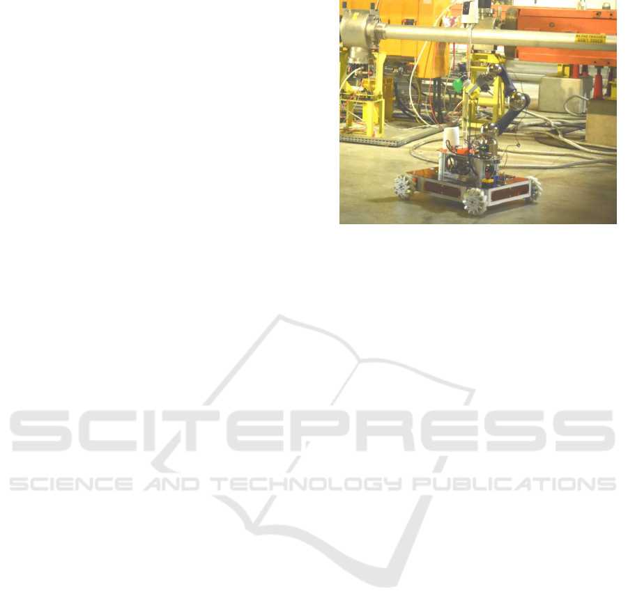
The vision system has been integrated on a robot
developed at CERN with a mobile base and a Schunk
Arm Powerball, Figure 1. For the management of the
robot and its multiple systems, a dedicated graphi-
cal user interface has been developed(Lunghi et al.,
2016).
3 PROPOSED ALGORITHM
The estimation of the position and the rotation of the
object has been solved developing the proposed al-
gorithm that is adaptable to different target objects,
Figure 2. The algorithm proposed uses mainly Point
Figure 1: Robot developed at CERN for surveying tasks.
Cloud Library, therefore the input will be a point
cloud, this is done in the first block of the flow chart.
The main problem of working with point clouds of
metallic objects is that these objects produce reflec-
tions that give an incomplete point cloud, Figure 3.
This cannot be avoided by modifying the lights, be-
cause the RGBD cameras work with their own light
projector. Therefore, the proposed algorithm must
work with miss information on the depth field and a
high noise.
The novel idea of the algorithm is the use of clus-
tering algorithms and segmentation to find a robust
point versus changes in the position of the camera,
this is done in the Filtering and FindCorners blocks
of the flow chart. As this point is robust, it will al-
ways be the same point even if the camera is in differ-
ent position. Once obtained the point, it can be known
the rest of the points of the object overlapping a Point
Cloud obtained from a CAD of the object, Figure 4.
To match this point cloud with the detected point in
the point cloud of the camera, the center of the CAD
point cloud is changed and it is located at the same
point that is going to be detected.
Finally, only the point cloud of the CAD should
be moved to the distance XYZ of the detected point.
In this way we can know the position of the object
and reconstruct it in 3D. The parts of the target lost
or occluded, appear reconstructed in the point cloud,
Figure 5.
To locate the robust points, a plane of the object
that contains them must be located. This is usually
given at the top of the objects. Therefore, a series of
point filtrations will have to be performed in order to
locate that plane. A general filtering algorithm has
been developed whose Flow Chart is in Figure 6. Fol-
lowing the steps of the flow chart, the algorithm gets
a surface from which it is easy to extract the robust
points through FindCorners.
Novel Pose Estimation System for Precise Robotic Manipulation in Unstructured Environment
51
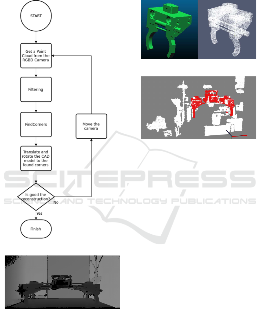
Figure 2: Flow Chart of the Algorithm.
Figure 3: The black zones are null data in the depth field
caused by reflections of the light of the projector.
Several methods have been developedfor the filtering:
DepthFilter: The target objects must be a bit near of
the camera, so we can filter distant points.
HeightFilter: This method has the same purpose of
Figure 4: Transformation from CAD mesh to Point Cloud.
Figure 5: Three-dimensional reconstruction of the object
using the algorithm of this paper.
DepthFilter and it allows remove points of the tar-
get object far from the plane that we want to find.
Clustering: This methods allows to filter parts of
less interest of the point cloud. We take the bigger
parts.
ExtractSlice: This is the main part of the algorithm,
it allows to find the plane, iteratively search planes
with a certain normal, between a intervals. We ap-
ply two times this method, one to detect a thick
plane, Figure 7, this allows us to filter a lot of
points, and don’t detect false planes, such as the
surface of small and useless parts. And after that
we apply again this method to extract the surface
of the detected thick plane, Figure 8.
FindCorners: Once the desired plane is found, it is
necessary to locate the corners, usually we search
for the top corners with this method.
A priori the CAD model of the object is taken and
its center is changed to the point that is searched with
the algorithm. This model then moves to the position
found and rotates to fit with both points, the left and
right points; this is done in the ”Translate and rotate
the CAD model to the found corners” block of the
flow chart in Figure 2. Thus finally one has the three-
dimensional reconstruction of the object.
Finally if the matching fails, autonomously the
robot can move the camera and try with a new one
point cloud.
ICINCO 2017 - 14th International Conference on Informatics in Control, Automation and Robotics
52
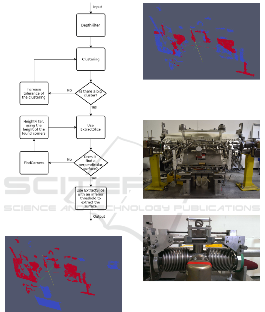
Figure 6: Flow Chart of the Filtering box in Figure 2.
Figure 7: Find the desired plane, filtering another planes of
lesser importance.
4 VALIDATION AND TESTS
The objects selected in this project correspond to a
collimator (Assmann et al., 2006), Figure 9. The col-
limators are of vital importance for the correct opera-
Figure 8: Extract the surface of the desired plane.
tion of the LHC and therefore have great importance
in technical inspections. In addition they are one of
the hot spots of radiation in the LHC.
Figure 9: Photography of a collimator.
Figure 10: Photography of a piece of the collimator system,
the separator.
This algorithm works because a few restrictions:
• The camera is in front of the target.
• The targets are always straight, it can not be lying
down.
• The targets are rigid.
It has been proven that the developed algorithm
works with position errors less than 1cm in the case
of the separator and between 2 and 3cm in the case
of the collimator. This shows that the error depends
Novel Pose Estimation System for Precise Robotic Manipulation in Unstructured Environment
53
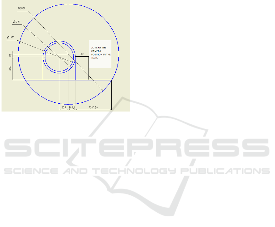
on the distance to which the camera is located, in the
case of the collimator being larger the camera was sit-
uated between 65cm and 75cm further,this distance is
because of the limited dimensions of the LHC tunnel,
Figure 11.
Figure 11: Schematic of a cross section of the LHC tunnel.
During the tests, Figure 12, it has been verified that
the processing time of the algorithm is between 5 and
10 seconds. This depends on the segmentation op-
eration, which must sometimes iterate over and over
again until it finds the right plane. The times are quite
acceptable, since the algorithm must be run only once,
because the global position is known.
The test point clouds were taken at distances to the
target between 50 cm and 136 cm, which is the maxi-
mum distance in the tunnel, Figure 11.
5 FUTURE DEVELOPMENT
As seen in the validation tests on large pieces, such
as the collimator, the error of the estimated position
increases, approaching levels that would cause prob-
lems in tele-operation. One way to reduce this error is
to make a second estimation of the position. Once the
first estimation is made, the camera in the robot arm
can be approached to a predetermined part, this could
be done automatically. Using the algorithm to detect
that part of the large piece, it is detected with minor
errors. And since the position of that part is known
a priori with respect to the rest, this allows to reduce
the error of the global piece.
6 CONCLUSION
In this paper, a novel algorithm to detect a 6D pose
of an object was presented. The novel solution has
been shown to be robust to be deployed in harsh and
unstructured environment, like the CERN accelera-
tors complexes. The proposed solution is time-wise
light and allows the three-dimensional reconstruction
of an object. This aspects are fundamental for robotic
inspections and telemanipulation, in the specific for
detecting collisions and performing path planning in
areas that the 2D cameras detect incompletely.
REFERENCES
Assmann, R., Magistris, M., Aberle, O., Mayer, M., Rug-
giero, F., Jim´enez, J., Calatroni, S., Ferrari, A., Bel-
lodi, G., Kurochkin, I., et al. (2006). The final colli-
mation system for the lhc. Technical report.
Engel, J., Koltun, V., and Cremers, D. (2016). Direct sparse
odometry. In arXiv:1607.02565.
Engel, J., Sch¨ops, T., and Cremers, D. (2014). LSD-
SLAM: Large-Scale Direct Monocular SLAM, pages
834–849. Springer International Publishing, Cham.
Hinterstoisser, S. Holzer, S., Cagniart, C., Ilic, S., Kono-
lige, K., Navab, N., and Lepetit, V. (2011). Multi-
modal templates for real-time detection of texture-less
objects in heavily cluttered scenes.
Intel. Intel realsense camera r200 datasheet. [online].
Intel. Intel realsense camera sr300 datasheet. [online].
Lunghi, G., Prades, R. M., and Castro, M. D. (2016). An ad-
vanced, adaptive and multimodal graphical user inter-
face for human-robot teleoperation in radioactive sce-
narios. In Proceedings of the 13th International Con-
ference on Informatics in Control, Automation and
Robotics (ICINCO 2016) - Volume 2, Lisbon, Portu-
gal, July 29-31, 2016., pages 224–231.
Microsoft. Kinect hardware. [online].
Orbbec. Orbbec astra pro. [online].
Orbbec. Orbbec. how our 3d camera works. [online].
Prisacariu, V. and Reid, I. (2009). Pwp3d: Real-time seg-
mentation and tracking of 3d objects. In Proceedings
of the 20th British Machine Vision Conference.
Song, S. and Xiao, J. (2014). Sliding Shapes for 3D Object
Detection in Depth Images, pages 634–651. Springer
International Publishing, Cham.
Song, S. and Xiao, J. (2016). Deep Sliding Shapes for
amodal 3D object detection in RGB-D images.
Zeng, A., Yu, K.-T., Song, S., Suo, D., Jr., E. W., Rodriguez,
A., and Xiao, J. (2016). Multi-view self-supervised
deep learning for 6d pose estimation in the amazon
picking challenge.
ICINCO 2017 - 14th International Conference on Informatics in Control, Automation and Robotics
54
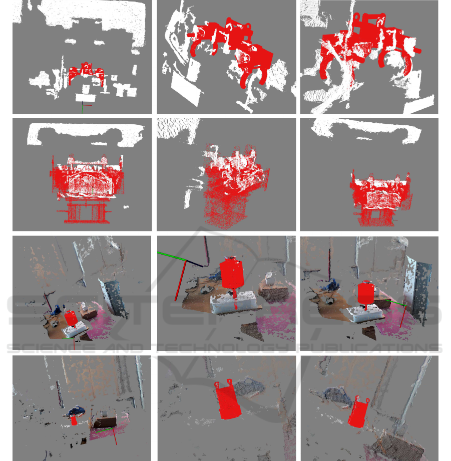
Figure 12: Reconstructions with different views of different point clouds of the separator (first row) and the collimator (second
row). And an oiler (third row) and a special socket (fourth row).
Novel Pose Estimation System for Precise Robotic Manipulation in Unstructured Environment
55
