
A Taxonomy and Systematic Approach for Automotive System
Architectures
From Functional Chains to Functional Networks
Johannes Bach, Stefan Otten and Eric Sax
FZI Research Center for Information Technology, Haid-und-Neu-Str. 10-14, 76131 Karlsruhe, Germany
Keywords:
Systems Engineering, System Architecture, Advanced Driving Assistance Systems, Automated Driving.
Abstract:
Technological advances enable realization of increasingly complex customer features in the automotive sector.
Traffic jam pilot or predictive energy management depict examples of recently introduced features that span
across different conventional vehicle domains. The increased interconnectivity and functional complexity im-
pose new requirements on the automotive systems engineering practice. The resulting challenge is to develop
integrated approaches that combine the established procedures with innovative techniques. To address this
challenge, we present a comprehensive taxonomy for existing automotive features. Based on this characteri-
zation, established industrial and new research approaches for logical system architectures are consolidated.
We introduce levels of hierarchy in the logical system architecture to facilitate systems engineering of inno-
vative functions and highly distributed features. The systematic approach provides a novel rationale for the
evolution from functional chains to functional networks in the automotive industry.
1 INTRODUCTION
Within the last decade a multitude of Advanced
Driver Assistant Systems (ADAS), such as Adap-
tive Cruise Control (ACC) and Lane Keeping Assist
(LKA) were introduced into the automotive market.
These features leading the way, automated driving be-
comes a reality (Becker et al., 2014). The new featu-
res are enabled by the steadily advancing technologi-
cal progress, which provides high-performance com-
puting in automotive environments. The new features
raise the functional complexity regarding utilized al-
gorithms, distribution of functions and the amount of
processed information, which has a considerable im-
pact on Electrics/Electronics (E/E) system architec-
tures. Current development methods and approached
are not sufficient to cope with the new complexity.
Several roles, teams and organizations participate
in the development of an automotive system. Scatte-
ring over different development locations leads to col-
laborative development (Weber and Weisbrod, 2002).
The development in automotive vehicles is histori-
cally structured into different domains (Reinhardt and
Kucera, 2013), such as powertrain, safety and chassis.
This modularization evolved from the product per-
spective and lead to corresponding organization struc-
tures to facilitate product engineering (Weber, 2009).
The domains originate from mechanical engineering
and were expanded with electrical and information
processing aspects. Within the different domains,
several approaches for development processes, met-
hods and tools are established and integrated into the
overall product development process. These methods
serve different needs and foci of the engineers, which
differ from domain to domain. As upcoming custo-
mer features lead to fuzzy system borders, the diffe-
rent domains’ development is moving closer together
(Haas and Langjahr, 2016). The integration and colla-
boration of domains is necessary without abandoning
methodological flexibility and individuality.
For Original Equipment Manufacturer (OEM),
well-established and long-existing systems such as
Electronic Stability Control (ESC) are iteratively op-
timized achieving a high-level of maturity. Supplier
structures and adjacent business units, such as pur-
chase or after sales, are shaped to the originated
needs. As new highly-integrated features partly col-
lude with the existing systems, the question of how to
use legacy systems during development poses a chal-
lenge. To foster the reuse of specific functionalities
of the established systems is a key issue for efficient
development.
Novel research and development approaches for
systems engineering focus on automated driving
90
Bach, J., Otten, S. and Sax, E.
A Taxonomy and Systematic Approach for Automotive System Architectures - From Functional Chains to Functional Networks.
DOI: 10.5220/0006307600900101
In Proceedings of the 3rd International Conference on Vehicle Technology and Intelligent Transport Systems (VEHITS 2017), pages 90-101
ISBN: 978-989-758-242-4
Copyright © 2017 by SCITEPRESS – Science and Technology Publications, Lda. All rights reserved
(Matthaei and Maurer, 2015), (Tas et al., 2016) do not
comprehensively cover the aspect of legacy systems.
The presented functional architectures mainly focus
on the automated driving or ADAS domain. There-
fore, focusing on assisting and automating functional
aspects and applying hierarchization without consi-
deration of the relevant conditions of adjacent dom-
ains. A comprehensive approach for the abstraction
and description of the functional architecture with re-
spect to different level of integration and complexity
of features is required.
To overcome these impediments, we present a
taxonomy for existing automotive customer features
across all domains, structuring them into different le-
vel of complexity. The taxonomy forms a basis to
provide a systematic approach for systems engineer-
ing with a focus on functional aspects. This systema-
tic approach can be further elaborated to consider the
impact on development processes.
The paper is structured as followed: Section 2
presents the state-of-the-art of systems engineering
and automotive architectures. Our cross-domain taxo-
nomy for current and upcoming electric/electronic fe-
atures is elaborated in Section 3. Our proposed ap-
proach for logical architectures and hierarchization is
given in Section 4. Section 5 demonstrates the appli-
cability of the approach on exemplary automotive fe-
atures. A conclusion and outlook on further activities
is presented in Section 6.
2 STATE OF THE ART
Systems engineering is a discipline to ”guide the engi-
neering of complex systems” (Korsiakoff et al., 2011).
The term ”System” is widely spread across different
fields and application domains and several approaches
for development are established. Within the automo-
tive area, the system ”Vehicle” is partitioned into dif-
ferent domains structuring the mechanical key com-
ponents of the vehicle (Weber, 2009). In the con-
text of this paper, we focus on automotive E/E sys-
tems engineering, which consists of several different
fields such as architectures, management, modeling
and operation research (Korsiakoff et al., 2011). In
the automotive domain, the management of develop-
ment processes if commonly based on the V-Model.
The AutomotiveSPICE (Automotive-SIG, 2015) spe-
cifies an established process reference that integrates
the V-Model approach. In this contribution, we fo-
cus on the architecture and structuring of automotive
embedded systems to facilitate the process of systems
engineering.
2.1 System Architecture
Several approaches and methods for the structural
description of system architectures (ATESST2 Con-
sortium, 2013), (Pohl et al., 2012), (Vector Informatik
GmbH, 2016) follow a model-based approach. The
principle of abstraction contributes to reduced com-
plexity (Korsiakoff et al., 2011) and facilitate system
understanding (Bhave et al., 2011). It enables the
structured analysis of specific topics, such as functi-
onal safety (Adler et al., 2012). Common abstraction
layers of automotive embedded systems are Logi-
cal Architecture, Software Architecture and Technical
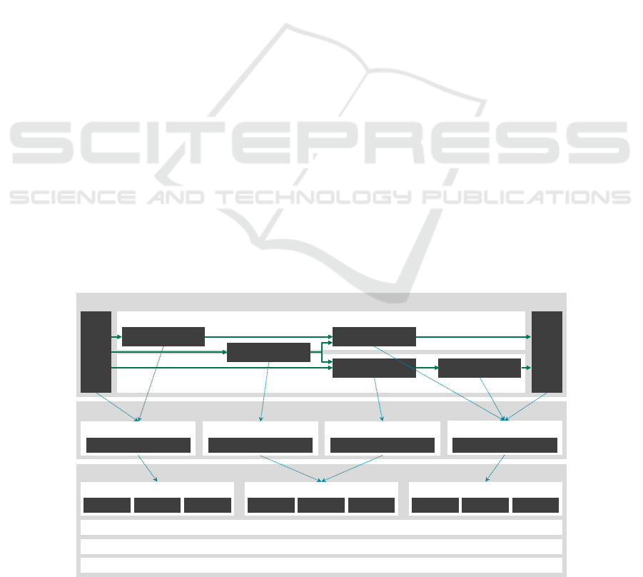
Architecture. A basic overview is given in Figure 1.
The abstraction layers provide a partial descrip-
tion of the system based on different perspectives
Logical Architecture
Software Architecture
Technical Architecture
Chain of Effects - Feature A
Chain of Effects - Feature B
Perception
Action
Function 2
Function 3
Function 4 Function 5
Function 1
Software Component A
Implementation
Software Component B
Implementation
Software Component C
Implementation
Software Component D
Implementation
Electronic Control Unit 1
ADC/DAC CPU Memory
Electronic Control Unit 2
CPU 1 CPU 2 Memory
Electronic Control Unit 3
ADC/DAC CPU Memory
Communication Network
Electric Circuits
Wiring Harness
Figure 1: Three abstraction levels of the automotive system architecture and mapping of functional behavior to software
components and electronic control units. Depiction referring to (Broy et al., 2009) and (Sch
¨
auffele and Zurawka, 2012).
A Taxonomy and Systematic Approach for Automotive System Architectures - From Functional Chains to Functional Networks
91

(Zhan and Krishnan, 2011), using the principle of
modularization of blocks and connections. Also hier-
archization and encapsulation of artifacts to describe
different levels of detail is intended. Between the arti-
facts of different abstraction layers, interconnections
and relations with distinct semantic are present (Pohl
et al., 2012). The example in Figure 1 depicts relati-
ons, which describe the partitioning of functional en-
tities into software components for integration on dis-
tinct Electronic Control Unit (ECU)s.
2.1.1 Logical Architecture
The logical architecture is a breakdown of a feature
”into interacting functional components” (Pretschner
et al., 2007). It represents the functional decomposi-
tion of a system into functional elements, which pro-
vide the functionality described in the corresponding
requirements. The logical architecture focuses on the
functional aspects, the logical interfaces and the co-
herence between the functional elements. It is com-
pletely independent from technical considerations or
software specific issues. A common approach in the
automotive area for the structuring of logical archi-
tectures is the usage of chains of effect to describe an
overall approach from sensing to acting (Sch
¨
auffele
and Zurawka, 2012). Demands for more elabora-
ted concepts to improve the structuring of increasing
complex features are initially addressed in (Holder
et al., 2012) and (Pretschner et al., 2007). Descrip-
tion of the functional element’s internal behavior is
highly depending on the associated domain and not in
scope of this contribution.
2.1.2 Software Architecture
The software architecture describes the different
software components and the partitioning of the
functional elements, including basic software (ope-
rating system and middleware) and communication
(Sch
¨
auffele and Zurawka, 2012). A standardized
middleware for software components allows reuse of
the basic elements, for automotive embedded sys-
tems this is given by the AUTomotive Open System
ARchitecture (AUTOSAR) (AUTOSAR development
cooperation, 2015). It specifies a software frame-
work and architecture consisting of basic software
elements, a run-time environment (RTE) and appli-
cation software components to enable reuse and sca-
lability.
Improvements and extensions for AUTOSAR in-
troduce adaptive deployment, service-oriented com-
munication and dynamic scheduling and applica-
tion execution as well as integration in new high-
performance processor architectures. The related spe-
cification under the term ”AUTOSAR adaptive” is
currently under development within the AUTOSAR
partnership (Fuerst, 2015).
2.1.3 Technical Architecture
The technical architecture specifies the integration le-
vel, which contains the hardware units to execute
the defined software components (Pretschner et al.,
2007). This comprises the ECU, actuators and sensors
and their interconnections. In automotive systems
engineering, the technical architecture is commonly
further refined to represent specific E/E aspects, such
as electric circuits and the wiring harness. The techni-
cal system architecture is based on a comprehensive
E/E topology containing a segmentation into previ-
ously introduced domains, such as body, chassis and
comfort. The current E/E architectures often reflect
the organizational structure introduced by segmenta-
tion of the car’s mechanical structure. Historically,
single ECUs were introduced to perform indepen-
dent functionality (Leen and Heffernan, 2002), con-
nected with a single centralized gateway (Streichert
and Traub, 2012) .
With increasing complexity and an increasing
number of ECUs, domain-controlled E/E architectu-
res with centralized domain-controllers were introdu-
ced (Reinhardt and Kucera, 2013), (Stolz et al., 2010).
This trend was an initial reflection to expanding sy-
stem boundaries, more complex functional chains and
higher integration of features. For each domain, mas-
ter controllers were introduced to facilitate domain-
comprehensive features. The evolution of technical
system architectures is thus tightly coupled with the
increasing interaction and networking of the logical
architecture. The current development leads to centra-
lized cross-domain E/E architectures based on high-
performance computing units (Navale et al., 2015),
(Haas and Langjahr, 2016).
2.2 Architecture Concepts for
Automated Driving
Research in the field of automated driving provides
various approaches to describe the system architec-
ture of research concepts. Stiller (Stiller et al., 2007)
provides a cognitive oriented approach of percep-
tion, planning and action tasks. Different layers clas-
sify the abstract representation of functional elements.
The architecture concept provided by Bauer (Bauer
et al., 2012) is categorized into a mission layer, a
coordination layer and a behavior layer. Each layer
consists of elements of the world model class, the
planning class and the HMI class. The utilized sen-
VEHITS 2017 - 3rd International Conference on Vehicle Technology and Intelligent Transport Systems
92

sors, actuators and the driver form the system envi-
ronment. The influence of human-machine interacti-
ons on system architecture is discussed by Flemisch
(Flemisch et al., 2014). Based on the psychological
categorization of the Dynamic Driving Task (DDT)
into navigation, guidance and control, the automation
system provides an interface on each level. Matt-
haei (Matthaei and Maurer, 2015) proposes a ”functi-
onal system architecture for an autonomous on-road
motor vehicle”. It applies a similar categorization
into a strategic level, a tactical level and an operati-
onal level and a further distinction between localiza-
tion, perception and mission accomplishment. An im-
plemented system architecture for automated driving,
using production vehicle sensors and additional pro-
totyping sensors, was presented by Aeberhard (Ae-
berhard et al., 2015). Buechel (Buechel et al., 2015)
presents the prototype of an automated electric vehi-
cle. The proposed software architecture consists of
the three components data fusion, trajectory planning
and trajectory controller, which is mapped to a cen-
tralized E/E architecture.
3 TAXONOMY FOR CURRENT
AND UPCOMING
ELECTRIC/ELECTRONIC
FEATURES
Todays technical compendiums of carmakers are
crammed with a high variety of customizable featu-
res. A significant proportion of those features is based
on E/E functionality. With rising complexity of and
dependencies between features, the established auto-
motive systems engineering methods and abstraction
concepts are reaching the limits of their capability. To
identify boundaries and necessary extensions of cur-
rent systems engineering methods we start with es-
tablishing a comprehensive overview of current and
upcoming E/E features. Our goal is to integrate well-
established features of the automotive industry and
current concepts of research groups within one con-
sistent taxonomy.
Our proposed taxonomy distinguishes features by
three main categories. Integrated features are closely
related to a specific mechanical domain of the vehi-
cle. They represent the E/E content necessary to ac-
complish the targeted operation of physical compo-
nents of the vehicle. Distributed features combine in-
dividual components of different domains to enable
additional capabilities. These features do not neces-
sarily require additional mechanical hardware com-
ponents. Their functional behavior can be expres-
sed as the sequential combination of available infor-
mation and usable actuators to provide added value.
Cross-linked features connect various functional ele-
ments and depend on the joined manipulation of the
behavior of independent and domain separated com-
ponents. They conflate various sources of informa-
tion to achieve a comprehensive representation of the
vehicle’s state and surroundings. This representation
forms the basis for cognitive and predictive features,
including but not limited to high automation levels.
Figure 2 depicts our proposed taxonomy. It classi-
fies and combines vehicular features of existing series
cars and features of current research. The taxonomy’s
features available in series cars represent an abstrac-
ted set of the offered features of major car companies.
We analyzed the online presence of BMW
1
, Daim-
ler
2
, Ford
3
, Peugeot
4
, Toyota
5
and VW
6
to select the
most common features. Research features were se-
lected to cover a range as wide as possible.
3.1 Integrated Features
As stated above, the integrated feature level subsumes
the E/E content to operate the physical components of
the vehicle. This entails a close proximity to specific
mechanical units and commonly involves the usage
of a dedicated ECU. Most sensors and actuators re-
quired for the assigned task of the feature are directly
attached to the dedicated ECU. Integrated features are
mainly based on proprioceptive sensors. Propriocep-
tive sensors obtain information about the internal state
of the vehicle (Bengler et al., 2014).
Our taxonomy differentiates the integrated featu-
res into the established vehicle domains. Weber (We-
ber, 2009) defines five of the six domains we ap-
ply. The powertrain domain contains ”all functions
controlling the generation of driving power and its
conversion into propulsion”. The taxonomy includes
the features automatic transmission, engine control,
1
BMW Technology Guide, Bayeris-
che Motoren Werke Aktiengesellschaft,
http://www.bmw.com/com/en/insights/technology/
technology guide/index.html
2
Welcome to the Mercedes-Benz TechCenter, Daimler
AG, https://techcenter.mercedes-benz.com/en/index.html
3
Advanced technology at your fingertips, Ford Motor
Company, http://www.ford.com/cars/focus/features/#page=
FeatureCategory4
4
Technologies & Innovations, Automobiles Peugeot,
http://www.peugeot.com/en/technology
5
Toyota Technology, Toyota Motor Sales, U.S.A., Inc.,
http://www.toyota.com/technology/
6
Technik auf den Punkt gebracht., Volkswagen
AG, http://www.volkswagen.de/de/technologie/technik-
lexikon.html
A Taxonomy and Systematic Approach for Automotive System Architectures - From Functional Chains to Functional Networks
93

Cross-Linked Features
Automating
Advisory
Assisting
Distributed Features
Advisory
Supporting
Assisting
Integrated Features
Infotainment
PowertrainBody
Safety
Chassis
Anti-lock braking
Traction
Control
Automatic
Transmission
Airbag Control
Engine
Control
Hill Assist
Stability Control
Automated Valet
Parking
Traffic Jam Pilot
Highway Pilot
Adaptive Cruise
Control
Lane Keeping
Assist
Blind Spot
Monitor
Adaptive High
Beam
Eco-Drive
Advice
Navigation
Full Driving
Automation
Park Assist
Range
Estimation
Power Steering
Audio and Video
Communication
HMI
Access Management
Anti-Theft System
Air Conditioning and
Heating
Seat Belt Tensioner
Windows and Wipers
Seats and Comfort
Rear Axle Steering
Power Grid
Battery Management
Converter Control
Damping and
Suspension Control
Lights and Interieur
Adaptive Bend
Lighting
Lane Departure
Warning
Collision
Warning
Speed Limit
Warning
Adaptive
Aerodynamics
Trailer Assistant
Traffic Adaptive
Routing
Start-Stop
System
Park Distance
Warning
Road Condition
Warning
Green Light Speed
Advisory
Predictive Cruise
Control
Lane Change Assist
Rear Impact
Protection
Supporting
Emergency Call
Collision Mitigation
Range Optimization
Recuperation
Control
Figure 2: Taxonomy of current and upcoming E/E features. Integrated features are grouped by vehicle domains, distributed
and cross-linked features by level of interference.
traction control and hill assist as a representative fea-
ture set of the powertrain domain. The safety domain
on integrated feature level includes the passive safety
features airbag control and seat belt tensioner. More
sophisticated active safety features are classified as
distributed features. The chassis domain includes fea-
tures to control the vehicle dynamics, providing a safe
and attractive driving experience. Stability control,
anti-lock breaking and power steering describe featu-
res that mainly support safe and comfortable driving.
Rear axle steering, damping and suspension control
and adaptive aerodynamics particularly support agi-
lity. The body domain encompasses all features atta-
ched to the vehicle body, like lights, windows, wipers,
seats and air conditioning as well as the car’s access
management and anti-theft system. The infotainment
domain is the fifth vehicle domain based on Weber’s
definition. It summarizes the features for navigation,
communication, audio and video entertainment and
Human Machine Interface (HMI). To take advancing
electrification into account, the power grid domain
completes the integrated features. Battery manage-
ment and converter control represent features that are
part of 48 volt grids of hybrid electric vehicles as well
as high voltage grids of fully electric vehicles.
3.2 Distributed Features
Most of the currently available ADAS are represen-
ted by the distributed features class. The functio-
nal behavior of distributed features resembles a chain
of effects, the aforementioned sequential combination
of available information and usable actuators. The
functionality of distributed features is based on the
connection of different domains. They often intro-
duce and utilize exteroceptive sensors that provide
information about the surroundings of the vehicle
(Bengler et al., 2014).
The taxonomy categorizes distributed features by
level of interference into the three classes advisory,
supporting and assisting features. Assisting features
are specified by SAE automation level 1 (SAE inter-
national, 2016) as features that ”perform either lon-
gitudinal or lateral vehicle motion control [...]”. To
allow distinction between passive advisory and active
supporting features on level 0, we introduce the dis-
tinctive classes.
The advisory class contains features that utilize
information of integrated features and exteroceptive
sensors to provide additional information for safe and
comfortable driving and potentially to influence the
driver’s behavior. Collision warning, lane departure
warning, blind spot monitor and park distance war-
ning depict advisory features to gain additional safety.
Speed limit warning helps to stick to regulations and
eco-drive advice intends to influence the driver’s be-
havior to achieve a sustainable driving style. Range
estimation and traffic adaptive routing support the dri-
ver’s decisions regarding the selected route and stopo-
vers.
The supporting class covers all features that acti-
vely influence the vehicle’s state, but do not perform
longitudinal or lateral vehicle motion control. It en-
compasses features such as adaptive high beam and
adaptive bend light as well as automated start-stop.
Rear impact protection represents an active safety fe-
ature that aims to decrease the damage induced to pas-
sengers during standstill, rear-end collisions. Bogen-
rieder (Bogenrieder et al., 2009) describes an appro-
ach that utilizes a backwards oriented radar sensor to
detect an imminent rear-end collision.
The park assist and trailer assistant feature per-
VEHITS 2017 - 3rd International Conference on Vehicle Technology and Intelligent Transport Systems
94

form lateral control of the vehicle, while longitudi-
nal control always remains with the driver. Therefore,
these are automation level 1 features and part of the
assisting features class. The ACC feature performs
longitudinal control and the LKA feature performs la-
teral control. While operated individually, both fea-
tures represent automation level 1. If both systems
are activated simultaneously, the feature combination
represents automation level 2, ”Partial Driving Auto-
mation”. Consequentially, level 2 automation features
are included in the assisting features class.
3.3 Cross-linked Features
In the presented taxonomy, cross-linked features uti-
lize sensor networks to derive information or to influ-
ence several actuators. These features span functio-
nal networks in distinction to the sequential functio-
nal chains of distributed features. They are based on
the fusion of proprioceptive and exteroceptive sensor
information to obtain a realistic and complete model
of the vehicle’s internal state and surroundings. Si-
milar to distributed features, cross-linked features are
grouped into advisory, supporting and assisting clas-
ses with the addition of the automating class. It com-
prises features from automation level 3 upwards. By
SAE definition, these features perform the complete
DDT with or without fallback and within or without a
specific Operational Design Domain (ODD).
The road condition warning feature in the advis-
ory class is described in the Car2Car communication
consortium manifesto (Baldessari et al., 2007). Se-
vere road conditions are propagated via Car2Car com-
munication or back end service between road users.
The green light speed advisory feature is also defined
by the Car2Car consortium. It interacts with the road
infrastructure and provides an optimal speed advice,
averting an otherwise necessary red light stop. Both
features require lane accurate positioning and access
to various internal states and the communication plat-
form of the vehicle. Therefore, they are classified into
the cross-linked feature class.
The supporting class contains two energy mana-
gement related features, the range optimization and
the recuperation control. The range optimization cal-
culates the remaining energy of the vehicle and pre-
dicts the required energy to reach the desired des-
tination. If necessary, it shuts down power hungry
comfort features like heating and air conditioning and
limits the propulsion power. The recuperation con-
trol predicts the vehicle’s energy flows and for ex-
ample reduces battery load before long recuperation
phases, to prevent waste of energy due to battery heat
protection (Woestman et al., 2002). As these featu-
res influence various actuators and require predictive
map data, traffic flow information and internal sta-
tes for optimal performance, they are classified into
the cross-linked category. Emergency call and colli-
sion mitigation round out the supporting feature class.
These are active safety features that take action before
an imminent collision and automatically call help af-
ter an accident.
Equivalent to the distributed features, the assisting
class covers features of SAE automation level 1 and
2. The predictive cruise control feature controls the
longitudinal motion of the vehicle (Wahl, 2015). It
calculates an energy optimal velocity trajectory based
on predictive map data and proprioceptive and extero-
ceptive sensor information. The included lane change
assist feature guides the driver’s lane change maneu-
ver (Cramer et al., 2015). It requires various sensors
and predicts the surrounding traffic to calculate a safe
lane change trajectory (Nilsson et al., 2016). Both
feature’s depend on several sensing, processing and
acting primitive elements and, therefore, are classified
as cross-linked features.
All features from SAE automation level 3 up-
wards belong to the automating class of cross-linked
features. The example features traffic jam pilot,
highway pilot, automated valet parking (Nordbruch
et al., 2015) and full driving automation (Ziegler
et al., 2014) perform the complete DDT. The former
three features are designed for a specific operational
domain. Depending on their characteristics and im-
plementation, all automating features utilize more or
less comprehensive environmental perception and in-
terpretation. Beside the longitudinal and lateral con-
trol of the vehicle, the features must control several
actuators to perform the complete DDT. Automating
features comprise the highest level of cross-linking.
4 COMPREHENSIVE
HIERARCHIZATION FOR
LOGICAL SYSTEM
ARCHITECTURES
As stated in Section 2.1, based on established system
architecture modeling concepts, all functional beha-
vior of the introduced features is modeled within one
level of logical system architectures. Thereby, the
differing character and integration depth of the in-
dividual functional elements is not considered. The
representation resolves the complexity of the under-
lying functional dependencies and multiple usage sce-
narios of particular functional elements only to a limi-
ted degree. Hence, the systems engineering principles
A Taxonomy and Systematic Approach for Automotive System Architectures - From Functional Chains to Functional Networks
95

Operation Control
Fusion and Modeling
Vehicle State
Model
Static Environment
Model
Dynamic
Environment
Model
Lateral Motion
Control
Longitudinal
Motion Control
Power
Management
Driving Mode
Management
Driver State Model
Actuators
Lights
Active
Suspension
Engine Breaks HMI
Air
Conditioning
Flaps &
Spoilers
Gearbox and
Differentials
Steering
Motor
Wipers and
Windows
Cooling
Electronic
Converters
Battery Doors Speakers
Sensors
GNSS
Odometer
Gyroscope
Accelero-
meter
Camera
Lidar
Ultrasonic
Radar
Thermo-
meter
Barometer
Rain Sensor
Force and
Torque
Interfaces
Cellular
Network
Car2X
Steering
Wheel
Pedals
HMI
Raw Information Level
Physics Level
Filtered Information Level
Interpreted Information Level
Peripheral SystemsTrafficDriver Road WeatherVehicle Dynamics
Actuation ControlPerception
Stability
Control
Body
Control
Power Grid
Control
Engine Control
Coarse Positioning
Powertrain
Control
Object
Tracking
Electronic
Horizon
Lane Tracking &
Sign Recognition
Primitive
Motion
Power Steering
Control
Internal States &
Driver Actions
Interpretation, Prediction and Planning
Scene
Understanding
Traffic Object
Prediction
Longitudinal
Motion Planning
Lateral Motion
Planning
Driver PredictionPose Prediction
Mission Control
Energy
Optimization
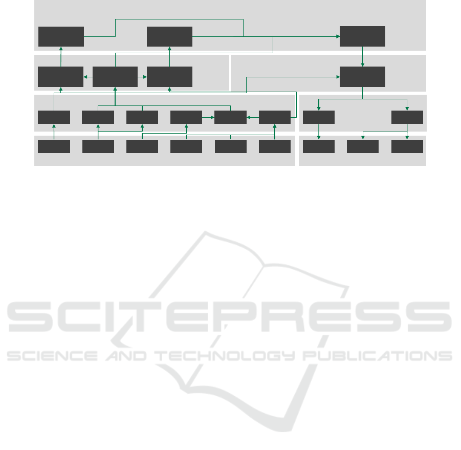
Figure 3: The proposed holistic hierarchization approach for the logical system architecture in the automotive domain.
of modularization, abstraction and hierarchization are
not employed to the full extent.
Section 2.2 outlines the approaches utilized by re-
searchers in the field of automated driving. The utili-
zation of psychological concepts offers a sound cha-
racterization for the functional components of auto-
mating features. This supports the structuring of fun-
damental sub-tasks of the DDT, but does not necessa-
rily support the entire systems engineering process.
Existing and established E/E systems were mostly
neglected by the described architecture representati-
ons. For an holistic approach we need a hierarchical
structure that supports a clear representation of the de-
pendencies between functional elements and includes
all automotive E/E features. It concurrently provides
an abstraction that facilitates adaption and association
of different shapes of systems engineering activities.
The aim of the proposed hierarchization of
functional elements is to introduce a comprehensive
domain-crossing functional architecture. The intro-
duced hierachization is based on the integration level
and the character of the processed information. This
enables a flexible description of the existing chain of
effects and their interaction with associated elements
within one systematic approach and simplifies precise
specification of interfaces. It facilitates the definition
of tailored templates for activities, such as verifica-
tion and validation, functional safety and release plan-
ning. These templates could guide developers, testers,
project and quality managers during the configuration
of function specific process implementations and the
selection of a balanced set of suitable methods and
tools.
Figure 3 depicts our newly introduced hierachiza-
tion for the logical system architecture. The classified
features of Section 3 were broken down into principal
functional elements and arranged to represent a cloc-
kwise flow of information. The layered approach pro-
vided by Stiller (Stiller et al., 2007) served as basis for
the development of the logical system architecture.
The type of information that is processed by the
respective element, is the major discrimination crite-
rion we apply to assign the elements to a particular
level. The physics level contains the functional ele-
ments to gain information from physical principles
and vice versa to influence the physics. On the raw
information level the derived raw information is filte-
red and actuation requests are processed. The filtered
information of different functional elements is combi-
ned via information fusion techniques within the fil-
tered information level and interpreted information is
used to operate the actuators. On the highest level
of the hierarchization, the interpreted information is
used to predict and abstract the state and behavior of
the system environment and the upcoming course and
actions of the vehicle are planned. In the following,
we explain these different levels, their characteristics
and possible consequences for future systems engi-
neering.
4.1 Physics Level
The physics level of the logical system architecture
is composed of sensors, interfaces and actuators and
comprises all interfaces to the system environment.
Sensors utilize physical measurement principles and
VEHITS 2017 - 3rd International Conference on Vehicle Technology and Intelligent Transport Systems
96

provide basis perception functions. They provide
raw information in form of discrete, unfiltered sam-
ple data. The type of supplied information ranges
from sampled physical quantities like force and tor-
que, acceleration and velocity to the raw image provi-
ded by a camera and the point cloud of a lidar sensor.
The sensors class also contains the control interfaces
of the driver and the Global Navigation Satellite Sy-
stem (GNSS) receiver.
The interfaces class enables the interaction with
affiliated technical systems. It provides access to cel-
lular networks and communication entities such as
Car2X, representing a bidirectional flow of informa-
tion.
The actuators encompass all functional elements
to affect the vehicle state and its environment as a
physical system. The powertrain elements engine, ge-
arbox and differentials influence the propulsion and
the flow of energy of the vehicle. By application of
steering torque, the steering motor affects the lateral
movement of the vehicle, but also acts as an interface
towards the driver. Active suspension and flaps and
spoilers alter the properties of aero- and vehicle dyn-
amics. Further functional elements serve a supporting
purpose (e.g. cooling, wipers or lights) and to influ-
ence the driver (e.g. HMI, speakers).
4.2 Raw Information Level
This level contains the functional elements required
for filtering and processing of raw signals and to drive
the actuators. The functions within the perception
class process the physical sensor’s raw data to derive
tangible information about the vehicle’s primitive mo-
tion and internal states. Coarse positioning is achie-
ved by interpretation of the pseudoranges in the na-
vigation satellite receiver and the electronic horizon
provides information about the upcoming road seg-
ment from an internal data storage. Images and point
clouds are processed to extract surrounding objects,
lanes and traffic signs.
The actuation control class drives and controls the
mechanical components of the vehicle via the physi-
cal actuators. It represents the basic functional com-
ponents of the integrated features that are essential
for the vehicle’s operability. The software implemen-
tation of functions on this level is subjected to hard
real-time constraints.
While the elements of the physics level represent
the functional share of mechanical and electrical har-
dware components, the raw information level contains
the functional part of the embedded software asso-
ciated with those elements. Its development should
be coupled with the processes of the physical level.
On this level, the development of components is com-
monly carried out by Tier 1 suppliers. Validation and
verification of the functional elements can mostly be
done independent of other elements. The obtained
information is commonly shared within the related
domain of the vehicle’s communication network.
4.3 Filtered Information Level
Functions on the filtered signal level perform fusion
and abstraction of the various detached information
sources and control the vehicle operation. The infor-
mation of the proprioceptive and exteroceptive sen-
sors is accumulated in the interpretation class. The
static and dynamic environment model provide a con-
densed and consistent representation of the vehicles
surroundings. The vehicle state model consolidates
all internal vehicle states and the driver state model
describes the driver’s features, such as level of atten-
tion and driving style.
The functions to control the lateral and the longi-
tudinal motion of the vehicle are the most important
items of the operation control class. Their task is to
achieve the targeted velocity and vehicle pose within
the operational limits. The driving mode management
coordinates the underlying functions to attain a well-
attuned driving experience. The power management
approves and limits power consumption of the vari-
ous components and coordinates the recuperation of
electrified vehicles.
The functions of the filtered information level are
not essential for the operability of the vehicle, but
enable distributed features. The included longitudi-
nal and lateral control elements are part of the assis-
ting and automating features. The functions on this
level are subjected to soft real-time constraints. Ve-
rification and validation of these functions is perfor-
med on the interface level. Simulation based techni-
ques require modeling of not only the vehicle physics
and environment, but also modeling of all underlying
functional elements implemented in software.
4.4 Interpreted Information Level
The interpreted information level contains cognitive
functions for interpretation, prediction and planning.
Stochastic models enable the prediction of the beha-
vior of traffic objects and driver intentions. The infor-
mation of the vehicle state model facilitates the pre-
diction of the vehicle’s pose. The functional element
scene understanding represents the interpretation of
the aggregated information. The longitudinal and la-
teral motion planning functions are based on the inter-
preted information and act on the underlying control
A Taxonomy and Systematic Approach for Automotive System Architectures - From Functional Chains to Functional Networks
97

functions. A dedicated element for energy optimiza-
tion enables the range optimization and the recupera-
tion control features. The mission control function is
an essential part of all automation features. It coor-
dinates the individual elements to accomplish the dri-
ving task.
The functional elements of the interpreted infor-
mation level are best suited for implementation on
a centralized, high-performance control unit, as the
amount of data necessary to provide the described in-
formation exceeds the capability of established com-
munication networks. The functional elements of
the interpreted information level resemble a service-
oriented approach. Therefore, no guarantees for real-
time constraints are given. Simulation models for ve-
rification and validation of these high level functions
do not need detailed models of the vehicle mecha-
nics or the physical background of the utilized sen-
sors. Emulation of the model based environment re-
presentation and the control behavior of the filtered
information level is sufficient.
5 REPRESENTATION OF
SELECTED FEATURES
WITHIN THE PROPOSED
LOGICAL SYSTEM
ARCHITECTURE
The elements within our proposed logical system ar-
chitecture were derived from the analysis and taxo-
nomy of existing and conceptual automotive features
in Section 3. In the following, we demonstrate the ap-
plicability by modeling selected features of all three
main categories of the taxonomy. The modeling of
established features shows the ability of our approach
to maintain legacy content. The representation of re-
search concepts proofs the ability to cope with future
demands.
5.1 Integrated Features
Of the integrated feature class, the ESC and the po-
wer steering control are modeled within our proposed
logical architecture.
5.1.1 Power Steering Control
The power steering control feature serves as an actu-
ator to influence the lateral movement of the vehicle.
It applies a torque to the steering wheel to support the
driver actuation or to achieve a given target steering
position. The power steering described by Kim (Kim
et al., 2015) supports the driver’s steering intention.
It provides a detailed description of the architecture
of a power steering control feature for driver support.
The torque applied by the driver is sensed and ampli-
fied depended on the vehicle velocity. Naranjo (Na-
ranjo et al., 2005) describes a power steering feature
for automated control of the vehicle. It applies steer-
ing torque to control the steering position. To obtain
a satisfactory control behavior, the control is operated
with a duty cycle of 10 ms.
Therefore, the power steering feature consists of
the odometer and steering wheel elements of the sen-
sors class, the power steering control function and the
steering motor of the actuators class.
5.1.2 Electronic Stability Control
The ESC feature ”is an active safety technology that
assists the driver to keep the vehicle on the intended
path and thereby helps to prevent accidents” (Liebe-
mann et al., 2004). The yaw movement of the vehicle
is stabilized by individually controlling the tire slip
of each wheel. To avoid counteracting the driver, ”it
needs to accurately interpret what the driver intends
for the vehicle motion in order to provide added di-
rectional control” (Tseng et al., 1999).
Actuation Control
ActuatorsSensors
Engine
Breaks
Gearbox and
Differentials
Odometer
Stability Control
Pedals
Steering
Wheel
Gyroscope
Accelero-
meter
Powertrain Control
Figure 4: The chain of effects of an electronic stability con-
trol feature (Liebemann et al., 2004) described, using our
newly introduced logical system architecture abstraction.
Figure 4 depicts the logical system architecture of
the ESC. The current yaw rate and vehicle movement
is read in from a gyroscope, an odometer and an acce-
lerometer. The driver intention is derived from the
information of the steering wheel and the pedals. The
stability control functional element calculates the in-
dividual tire slips necessary to obtain a stable mo-
vement. Actuation of the brakes is directly applied,
the engine, gearbox and differentials are actuated via
the powertrain control function.
5.2 Distributed Features
To represent the distributed features class, we selected
the ACC feature as a longitudinal control feature and
the LKA feature as a lateral control feature.
VEHITS 2017 - 3rd International Conference on Vehicle Technology and Intelligent Transport Systems
98

5.2.1 Adaptive Cruise Control
The ACC feature depicts an assisting feature that con-
trols the vehicles longitudinal velocity and adapts it
to the velocity of leading traffic. Winner (Winner
et al., 2012) provides a comprehensive overview of
the ACC feature. The radar based perception of the
area in front of the vehicle is used to calculate and
control the vehicle’s velocity. The driver inputs are
monitored to detect an override by throttle actuation
and a deactivation by brake actuation. Moon (Moon
et al., 2008) describes a two-level control structure,
where the upper level controls the vehicles speed by
requesting accelerations and the lower level controls
the acceleration by throttle and brake actuation.
Actuation Control
Perception
ActuatorsSensors
Engine
Breaks
Gearbox and
Differentials
Odometer
Stability Control
Gyroscope
Accelerometer
Powertrain
Control
Primitive Motion
Object Tracking
Radar
Operation Control
Longitudinal
Motion Control
Figure 5: The core elements of the ACC logical system ar-
chitecture.
Figure 5 depicts the logical system architecture of
an ACC feature. For comprehensibility, the elements
for driver interaction, like activation and override, are
removed and only the core elements are represented.
The primitive motion of the vehicle is estimated ba-
sed on internal sensors information. The radar sig-
nal is processed by the object tracking function and
used to calculate and control the desired time-gap in
the longitudinal motion control function. Actuation is
performed via the stability control and the powertrain
control elements.
5.2.2 Lane Keeping Assist
The lane keeping assist feature assists the driver in the
lateral control task without without assuming control
of the complete DDT. Following Ishida (Ishida and
Gayko, 2004), ”The lane keeping assistance system
consists of a camera-equipped lane recognition unit,
the LKAS control unit, and the Electric Power Steer-
ing (EPS).” The lane tracking functions extracts the
lane markings in the camera image and calculates the
lateral deviation, orientation and curvature. This in-
formation is used as control variables in the lateral
motion control function. The actuation is a steering
torque applied via the power steering control and the
steering motor.
5.3 Cross-linked Features
Of the cross-linked feature class we selected the Pre-
dictive Cruise Control (PCC) feature of the assisting
class. Wahl (Wahl, 2015) describes the PCC as a fea-
ture for optimal longitudinal control. The ACC is ex-
tended to adapt the velocity to the road topology and
speed limits besides leading traffic. Figure 6 depicts
the logical architecture of the PCC feature.
The environmental perception of the ACC is ex-
tended by a camera system for lane tracking and
traffic sign recognition. A GNSS receiver provi-
des coarse positioning, which is used to provide the
upcoming road topology via the electronic horizon
function. A consistent model of the static environ-
ment, the vehicle state and the dynamic environment
is formed on the interpretation level.
The feature implements a model predictive cont-
rol strategy. Therefore, the pose of the vehicle and
the movement of the traffic object are predicted and
passed on. Bauer (Bauer and Gauterin, 2016) splits
up the control task of the PCC into two levels. This
approach maps to the longitudinal motion planning
element and the longitudinal motion control.
6 CONCLUSIONS
In this contribution, we presented a taxonomy for ex-
isting and upcoming automotive customer features. It
provides a broad overview of the current automotive
cosmos and facilitates the analysis of current challen-
ges to systems engineering practice.
To handle increasing functional complexity, we
introduced an hierarchical structure to the logical sy-
stem architecture. The classification is designed to
cover all vehicle domains and enable representation
of functional chains and networks. The structure pro-
vides a neat general view and simplifies assignment of
properties and interface specification. The systematic
approach allows combination of new and legacy ele-
ments to derive innovative features. Following on the
presented approach, future work involves the analysis
of the influence and potential benefit to product deve-
lopment. The structured representation of functional
elements allows a level-specific allocation of process
quality gates. Adaption of the subsequential align-
ment of process actions to the different hierarchy le-
vels fosters a harmonic feature ramp-up and enables
introduction of agile practices. Association of aligned
strategies for verification and validation and functio-
nal safety with the structured and holistic view on the
logical system architecture should provide a substan-
tial benefit.
A Taxonomy and Systematic Approach for Automotive System Architectures - From Functional Chains to Functional Networks
99
Actuation Control
Operation Control
Fusion and Modeling
Vehicle State
Model
Dynamic
Environment
Model
Static Environment
Model
Longitudinal
Motion Control
Interpretation, Prediction and Planning
Traffic Object
Prediction
Longitudinal
Motion Planning
Pose Prediction
Actuators
Breaks Engine
Gearbox and
Differentials
Sensors
GNSS Odometer Gyroscope
Accelero-
meter
CameraRadar
Basis Perception and Actuation
Stability
Control
Powertrain
Control
Coarse
Positioning
Object
Tracking
Electronic
Horizon
Traffic Sign
Recognition
Lane
Tracking
Primitive
Motion
Figure 6: The chain of effects of a predictive cruise control feature described, using our newly introduced logical system
architecture abstraction.
REFERENCES
Adler, N., Hillenbrand, M., M
¨
uller-Glaser, K. D., Metzker,
E., and Reichmann, C. (2012). Graphically notated
fault modeling and safety analysis in the context of
electric and electronic architecture development and
functional safety. In 2012 23rd IEEE International
Symposium on Rapid System Prototyping (RSP), pa-
ges 36–42.
Aeberhard, M., Rauch, S., Bahram, M., Tanzmeister, G.,
Thomas, J., Pilat, Y., Homm, F., Huber, W., and Ka-
empchen, N. (2015). Experience, results and les-
sons learned from automated driving on germany’s
highways. IEEE Intelligent Transportation Systems
Magazine, 7(1):42–57.
ATESST2 Consortium (2013). EAST-ADL Domain Model
Specification, 2.1.12 edition.
Automotive-SIG (2015). Automotive SPICE Process Asses-
sment / Reference Model. VDA QMC, Berlin, Ger-
many, 3.0 edition.
AUTOSAR development cooperation (2015). Specification
of RTE. Munich, 4.2.1 edition.
Baldessari, R., B
¨
odekker, B., Brakemeier, A., Deegener,
M., Festag, A., Franz, W., Hiller, A., Kellum, C.,
Kosch, T., Kovacs, A., Lenardi, M., L
¨
ubke, A., Me-
nig, C., Peichl, T., Roeckl, M., Dieter, S., Markus,
S., Stratil, H., V
¨
ogel, H.-J., Weyl, B., and Zhang, W.
(2007). CAR 2 CAR Communication Consortium Ma-
nifesto. CAR 2 CAR Communication Consortium,
Brussels, 1.1 edition.
Bauer, E., Lotz, F., Pfromm, M., Schreier, M., Cieler, S.,
Eckert, A., Hohm, A., L
¨
uke, S., Rieth, P., Abendroth,
B., Willert, V., Adamy, J., Bruder, R., Konigorski, U.,
and Winner, H. (2012). Proreta 3: An integrated ap-
proach to collision avoidance and vehicle automation.
at - Automatisierungstechnik, 60:755–765.
Bauer, K.-L. and Gauterin, F. (2016). A two-layer approach
for predictive optimal cruise control. In SAE Technical
Paper 2016-01-0634.
Becker, J., Aranda Colas, M., Nordbruch, S., and Fausten,
M. (2014). Bosch’s vision and roadmap toward fully
autonomous driving. Road Vehicle Automation, Lec-
ture Notes in Mobility, pages 49–59.
Bengler, K., Dietmayer, K., F
¨
arber, B., Maurer, M., Stiller,
C., and Winner, H. (2014). Three decades of driver
assistance systems. IEEE Intelligent Transportation
Systems Magazine, 6(4):6–22.
Bhave, A., Krogh, B. H., Garlan, D., and Schmerl,
B. (2011). View consistency in architectures for
cyber-physical systems. In Cyber-Physical Systems
(ICCPS), 2011 IEEE/ACM International Conference
on, pages 151–160.
Bogenrieder, R., Fehring, M., and Bachmann, R. (2009).
Pre-safe in rear-end collision situations. In Procee-
dings 21st International Technical Conferrence on the
Enhanced Safety of Vehicles, Stuttgart.
Broy, M., Gleirscher, M., Kluge, P., Krenzer, W., Merenda,
S., and Wild, D. (2009). Automotive architecture fra-
mework: Towards holistic and standardised system ar-
chitecture description. Technical report, Technische
Universit
¨
at M
¨
unchen.
Buechel, M., Frtunikj, J., Becker, K., Sommer, S., Buckl,
C., Armbruster, M., Marek, A., Zirkler, A., Klein, C.,
and Knoll, A. (2015). An automated electric vehicle
prototype showing new trends in automotive architec-
tures. In 2015 IEEE 18th International Conference on
Intelligent Transportation Systems, pages 1274–1279.
Cramer, S., Lange, A., and Bengler, K. (2015). Path plan-
ning and steering control concept for a cooperative
lane change maneuver according to the h-mode con-
cept. In 7. Tagung Fahrerassistenzsysteme.
Flemisch, F. O., Bengler, K., Bubb, H., Winner, H., and
Bruder, R. (2014). Towards cooperative guidance
and control of highly automated vehicles: H-mode
and conduct-by-wire. Ergonomics, 57(3):343–360.
PMID: 24559139.
Fuerst, S. (2015). Autosar the next generation - the adaptive
platform. In CARS Critical Automotive applications:
Robustness & Safety in 11th EDCC European Depen-
dable Computing Conference.
VEHITS 2017 - 3rd International Conference on Vehicle Technology and Intelligent Transport Systems
100

Haas, W. and Langjahr, P. (2016). Cross-domain vehicle
control units in modern e/e architectures. In 16. Inter-
nationales Stuttgarter Symposium, pages 1619–1627.
Holder, S., Hoerwick, M., and Gentner, H. (2012). Funk-
tionsbergreifende szeneninterpretation zur vernetzung
von fahrerassistenzsystemen. In AAET - Automatisier-
tes und vernetztes Fahren.
Ishida, S. and Gayko, J. E. (2004). Development, evaluation
and introduction of a lane keeping assistance system.
In Intelligent Vehicles Symposium, 2004 IEEE, pages
943–944.
Kim, J.-W., Lee, K.-J., and Ahn, H.-S. (2015). Development
of software component architecture for motor-driven
power steering control system using autosar methodo-
logy. In Control, Automation and Systems (ICCAS),
2015 15th International Conference on, pages 1995–
1998.
Korsiakoff, A., Sweet, W. N., Seymour, S. J., and Biemer,
S. M. (2011). Systems Engineering Principles and
Practice. John Wiley & Sons, Inc.
Leen, G. and Heffernan, D. (2002). Expanding automotive
electronic systems. Computer, 35(1):88–93.
Liebemann, E. K., Meder, K., Schuh, J., and Nenninger, G.
(2004). Safety and performance enhancement: The
bosch electronic stability control (esp). SAE Paper,
20004:21–0060.
Matthaei, R. and Maurer, M. (2015). Autonomous driving
- a top-down-approach. at - Automatisierungstechnik,
63(3):155–167.
Moon, S., Yi, K., and Moon, I. (2008). Design, tuning and
evaluation of integrated acc/ca systems. In 17th World
Congress of the International Federation of Automatic
Control (IFAC 2008), volume 41 of IFAC Proceedings
Volumes, pages 8546–8551.
Naranjo, J. E., Gonzalez, C., Garcia, R., de Pedro, T., and
Haber, R. E. (2005). Power-steering control architec-
ture for automatic driving. IEEE Transactions on In-
telligent Transportation Systems, 6(4):406–415.
Navale, V. M., Williams, K., Lagospiris, A., Schaffert, M.,
and Schweiker, M.-A. (2015). (r)evolution of e/e
architectures. SAE Int. J. Passeng. Cars Electron.
Electr. Syst., 8(2):282–288.
Nilsson, J., Br
¨
annstr
¨
om, M., Coelingh, E., and Fredriksson,
J. (2016). Lane change maneuvers for automated vehi-
cles. IEEE Transactions on Intelligent Transportation
Systems, PP(99):1–10.
Nordbruch, S., Quast, G., Nicodemus, R., and Scheiger, R.
(2015). Automated valet parking. In 7. Tagung Fahre-
rassistenzsysteme.
Pohl, K., Hoenninger, H., Achatz, R., , and Broy, M. (2012).
Model-Based Engineering of Embedded Systems - The
SPES 2020 Methodology. Springer-Verlag Berlin Hei-
delberg.
Pretschner, A., Broy, M., Krueger, I. H., and Stauner, T.
(2007). Software engineering for automotive systems:
A roadmap. In FOSE Future of Software Engineering.
Reinhardt, D. and Kucera, M. (2013). Domain controlled
architecture - a new approach for large scale software
integrated automotive systems. In 3rd International
Conference on Pervasive Embedded Computing and
Communication Systems, pages 221–226.
SAE international (2016). Taxonomy and definitions for
terms related to driving automation systems for on-
road motor vehicles.
Sch
¨
auffele, J. and Zurawka, T. (2012). Automotive Soft-
ware Engineering - Grundlagen, Prozesse, Methoden
und Werzeuge effizient einsetzen. Springer Fachme-
dien Wiesbaden GmbH, 5 edition.
Stiller, C., F
¨
arber, G., and Kammel, S. (2007). Coopera-
tive cognitive automobiles. In Proceedings of the 2007
IEEE Intelligent Vehicles Symposium, pages 215–220.
Stolz, W., Kornhaas, R., and Sommer, T. (2010). Dom-
ain control units the solution for future e/e architec-
tures? In SAE Technical Paper 2010-01-0686, pages
221–226.
Streichert, T. and Traub, M. (2012). Elektrik/Elektronik-
Architekturen im Kraftfahrzeug - Modellierung und
Bewertung von Echtzeitsystemen. Springer Berlin
Heidelberg.
Tas,
¨
O. S., Kuhnt, F., Z
¨
ollner, J. M., and Stiller, C. (2016).
Functional system architectures towards fully automa-
ted driving. In 2016 IEEE Intelligent Vehicles Sympo-
sium (IV).
Tseng, H. E., Ashrafi, B., Madau, D., Brown, T. A., and
Recker, D. (1999). The development of vehicle sta-
bility control at ford. IEEE/ASME Transactions on
Mechatronics, 4(3):223–234.
Vector Informatik GmbH (2016). PREEvision User Manual
Version 8.0. Stuttgart.
Wahl, H.-G. (2015). Optimale Regelung eines pr
¨
adiktiven
Energiemanagements von Hybridfahrzeugen. PhD
thesis, Karlsruher Institut fr Technologie.
Weber, J. (2009). Automotive Development Process.
Springer-Verlag.
Weber, M. and Weisbrod, J. (2002). Requirements engi-
neering in automotive development - experience and
challenges. In IEEE Joint International Conference
on Requirements Engineering (RE’02).
Winner, H., Danner, B., and Steinle, J. (2012). Hand-
buch Fahrerassistenzsysteme, chapter Adaptive Cruise
Control, pages 478–521. Vieweg+Teubner Verlag,
Wiesbaden.
Woestman, J., Patil, P., Stunz, R., and Pilutti, T. (2002).
Strategy to use an on-board navigation system for
electric and hybrid electric vehicle energy manage-
ment. US Patent 6,487,477.
Zhan, R. and Krishnan, A. (2011). Using delta model for
collaborative work of industrial large-scaled e/e archi-
tecture models. Model Driven Engineering Langua-
ges and Systems, 14th International Conference, MO-
DELS 2011, pages 16–21.
Ziegler, J., Bender, P., Schreiber, M., Lategahn, H., Strauss,
T., Stiller, C., Dang, T., Franke, U., Appenrodt, N.,
Keller, C., Kaus, E., Herrtwich, R., Rabe, C., Pfeif-
fer, D., Lindner, F., Stein, F., Erbs, F., Enzweiler, M.,
Knoppel, C., Hipp, J., Haueis, M., Trepte, M., Brenk,
C., Tamke, A., Ghanaat, M., Braun, m., Joos, A., Fritz,
H., Mock, H., Hein, M., and Zeeb, E. (2014). Ma-
king bertha drive - an autonomous journey on a his-
toric route. IEEE Intelligent Transportation Systems
Magazine, 6(2):8–20.
A Taxonomy and Systematic Approach for Automotive System Architectures - From Functional Chains to Functional Networks
101
