
DataFlow Analysis in BPMN Models
Anass Rachdi, Abdeslam En-Nouaary and Mohamed Dahchour
Institut National des Postes et T
´
el
´
ecommunications, 2, av ALLal EL Fassi Madinat AL Irfane, Rabat, Morocco
Keywords:
BPMN, Business Process Modeling, Formal Verification, Dataflow Anti-patterns, Information Systems.
Abstract:
Business Process Management and Notation (BPMN) is the defacto standard used in enterprises for model-
ing business processes.However, this standard was not provided with a formal semantics, which makes the
possibility of analysis limited to informal approaches such as observation. While most of the existing formal
approaches for BPMN models verification focus on the control-flow, only few has treated the data-flow angle.
The latter is important since the correct execution of activities in BPMN models is based on data’s availability
and correctness. In this paper, we present a new approach that uses the DataRecord concept, adapted for the
BPMN standard. The main advantage of our approach is that it locates the stage where the data flow anomaly
has taken place as well as the source of data flow problem. Therefore the designer can easily correct the data
flow anomaly.The model’s data flow problems are detected using an algorithm specific for the BPMN standard.
1 INTRODUCTION
Business Process Management (BPM), is a manage-
rial approach that enables an organization to ensure
that its processes are implemented effectively and ef-
ficiently. Therefore, it brings an additional value to
organizations by improving their performance, pro-
ductivity and customer services quality. One of the
most important phases that constitutes the life cycle
of Business Process Management is Business Pro-
cess Modeling. The latter is considered essential
for designing and analyzing business process mod-
els that compose information systems. It involves
the use of simple and intuitive modeling languages
that makes models understandable by all business ac-
tors (Business analysts, Technical developers, final
users. . .). One of the latest languages that verifies
these criteria is Business Process Modeling and No-
tation (BPMN 2.0) (OMG, 2011). It is an adopted
standard in both academia and industry that was de-
signed to provide a graphical notation for XML-based
business process languages, like Business Process Ex-
ecution Language (BPEL) (OASIS, 2007). However,
BPMN defines the execution semantics of flow ele-
ments with their data needs and data results only in-
formally, in a textual representation (Stackelberg et
al., 2014), which limits verification to using solely
informal techniques such observation and inspection.
Formal methods help us avoid flow control anomalies
as well as data flow errors. Since several approaches
have addressed the control flow problems (deadlock,
livelock . . .) (Dijkman et al., 2007),(PYH. Wong,
2008),(J.Ye et al., 2008),(Rachdi et al., 2016), we
will focus in this paper on formal methods that deal
with dataflow anomalies (Missing, lost, redundant
and inconsistent data. . .). In order to analyze formally
dataflow in BPMN, we usually define a mapping from
the graphical notation to a formal language such as
Petri Nets (PN). If we adopt the Petri net approach ex-
plained in (Stackelberg et al., 2014), we would have
to go through several and complex steps (Definition
of mapping & Unfolding rules, BPMN to PN trans-
formation, Process-specific anti-patterns generation,
Model checking . . .) before we get the dataflow er-
rors made in the BPMN model. Therefore, we have
taken a different approach that can detect the anti-
patterns representing dataflow anomalies using data
record concept (Kabbaj et al., 2015). The latter is di-
rect and simple and explains to the designer the origin
of the anomaly so he/she can fix it easily in remodel-
ing phase.In addition, this concept does not need sev-
eral operations to complete the desired analysis.
The remainder of this paper is structured as fol-
lows: The next section proposes the work related
to our approach. Section 3 introduces the technical
background needed for the rest of the paper; it is di-
vided into three major parts. The first one presents
BPMN elements as well as their main properties. The
second one presents the dataflow anti-patterns that
have to be avoided during the design phase and the
last one introduces the datarecord concept (Kabbaj et
al., 2015). Section 4 presents our contribution for the
Rachdi, A., En-Nouaary, A. and Dahchour, M.
DataFlow Analysis in BPMN Models.
DOI: 10.5220/0006271202290237
In Proceedings of the 19th International Conference on Enterprise Information Systems (ICEIS 2017) - Volume 2, pages 229-237
ISBN: 978-989-758-248-6
Copyright © 2017 by SCITEPRESS – Science and Technology Publications, Lda. All rights reserved
229

analysis and the verification of BPMN models by in-
troducing a formalization of the dataflow anti-patterns
as well as proposing an algorithm that detects these
dataflow errors.Section 5 concludes the paper and
presents future work. An example is used throughout
the paper to illustrate the proposed method.
2 RELATED WORK
Most approaches that deals with business process
analysis focus on the control flow perspective and ig-
nore the equally important data flow angle. Few work
has focused on the data flow verification in business
processes in general and in BPMN in particular.
Sadiq et al. (Sadiq et al., 2008) have highlighted
the importance of dataflow analysis in business pro-
cesses and identified seven types of data flow anoma-
lies: redundant data, lost data, missing data, mis-
matched data, inconsistent data, misdirected data, and
insufficient data. However, they have proposed no
formal solution to detect these anomalies.
In (Trcka et al., 2009), Trcka et al. formalized the
data flow errors using computational temporal logic
CTL*. The latter helps us detect dataflow errors in
WFD-nets (a variante of Petri-Net) by using some
standard model-checking techniques (Clarke et al.,
1999). However these techniques were not elaborated
explicity in this proposal.
Another approach was proposed in (Kabbaj et al.,
2015), where Kabbaj et al. have tried to anticipate
the data-flow errors during the modeling phase. This
is accomplished by providing a tool for real-time
analysis that triggered the verification process when-
ever a model fragment is added. Unfortunately, the
proposition has only covered the exclusive paths (i.e,
XOR branches) and not parallel paths (i.e, And-Split),
which leaves the inconsistent data anomaly uncovered
during the verification process.
To the best of our knowledge, (Stackelberg et al.,
2014) is the only approach that has treated the data
flow angle in BPMN Process models, in which Stack-
elberg et al. have used an extension of the BPMN-
Petri-net mapping to include the data dimension in
their analysis. The data flow errors were formal-
ized using CTL and detected using a specific model
checker. However, this proposal is complex and
has to go through several steps (Definition of map-
ping & Unfolding rules, BPMN to PN transforma-
tion, Process-specific anti-patterns generation, Model
checking . . .) in order to detect the data flow errors.
In our paper, we take a different approach that can
detect the anti-patterns representing dataflow anoma-
lies using data record concept (Kabbaj et al., 2015).
The latter is clear and simple and proposes some so-
lutions to the designer so he can avoid these data flow
errors. In addition, this concept is used conjointly
with a specific algorithm (one Procedure) to detect the
maximum of data flow errors while exploring the ex-
clusive and parallel paths of a business process.
3 BACKGROUND
This section presents the different concepts and spec-
ifications used in this paper namely, BPMN, Dataflow
anti-patterns and DataRecord.
3.1 Business Process Management &
Notation (BPMN)
Figure 1: BPMN elements.
BPMN is a recent notation standardized by OMG
and BPMI (OMG, 2011). It is considered user-
friendly to all company stakeholders (business ana-
lysts, technical developers, final users . . . ). It has re-
ceived a lot of interest and support from academia,
industry. BPMN provides users with a range of di-
verse components. They are divided into four sets:
flow objects (activities, events and gateways), con-
nection objects (control flow, message flow and as-
sociations), artifact objects (data stores, data objects,
data input and data output) and swim lanes (pools and
lanes within pools) as illustrated by figure 1.
Events can be partitioned into disjoint sets of start
events, intermediate events (intermediate message,
time and error events) and end events. A start event
indicates the start of a process while an end event rep-
resents the end of a process. An intermediate event is
used to indicate that something might happen during
the execution of a process. An activity is either a task
or a subprocess that can be used to provide some busi-
ness service, wait for a message from another partici-
ICEIS 2017 - 19th International Conference on Enterprise Information Systems
230
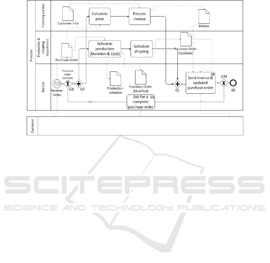
Figure 2: A Simple Order processing modeled in BPMN.
pant, or send a message to another participant. A gate-
way is a connector used to control sequence flows.
We distinguish between multiple types of gateways:
an AND-split gateway is used to create parallel flows
and an AND-join gateway is used to synchronize in-
coming parallel flows (Prandi et al., 2008). A XOR
data-based gateway defines a set of alternative paths;
each of them is associated with a conditional expres-
sion. Based on this condition, only one path can be
taken during the execution of the process.Conditions
can be based either on data-base entries or on exter-
nal events. An exclusive merge gateway is used as
a merge for alternative sequence flows (Prandi et al.,
2008).
In BPMN, we use artifacts objects (especially data
objects) to model documents (OMG, 2011), data, and
other objects that are read, created or updated dur-
ing the process flow. They can be mandatory or op-
tional (Stackelberg et al., 2014) but in case of they are
mandatory, they do interfere in the correct execution
of tasks or events. Therefore, in the rest of the paper,
we focus only on the mandatory data objects and not
on the optional ones.
An example of BP is shown in Figure 2. It rep-
resents a simple order processing, with four partici-
pants namely: the Customer, the Front-office Service,
The Production department and the Invoicing. This
model was elaborated based on the following scope
statements:
• The provider service receives a purchase order
from the customer
• If the purchase order is not complete, the service
asks for a complete one and the process is com-
pleted.
• If it is complete, the provider’s production depart-
ment generates the production schedule (cost &
duration) based on which we update the purchase
order.
• In parallel, the invoicing service starts calculating
the total price that will be included in the invoice
in addition to the customer infos.
• Once the production schedule is produced, the
production’s department starts preparing the ship-
ping schedule.
• The service can not send the invoice and the
updated purchase order (containing informations
about the shipping and production schedule) to
the customer unless the invoice and the shipping
schedule are both generated by their related activ-
ities.
Hereafter, we give BPMN a formal definition that
takes into consideration the data and control flow
components that are highlighted in this paper;
Definition 1 (Core BPMN Process): A core
BPMN process is a tuple P=(O
P
, F
P
, Data
P
, Indata
P
,
Outdata
P
) where :
• O
P
is a set of flow objects, which can be parti-
tioned into disjoint sets of activities A
P
, events E
P
,
and gateways G
P
,(Dijkman et al., 2007)
• E
P
can be partitioned into disjoint sets of start
events E
S
P
, intermediate events E
I
P
, and end events
DataFlow Analysis in BPMN Models
231

E
E
P
(Dijkman et al., 2007). Intermediate events E
I
P
may be partitioned into catch events (e.g., receive
message event) and throw events (e.g., send mes-
sage event) (OMG, 2011).
• G
P
can be partitioned into disjoint sets of paral-
lel fork gateways G
F
P
, parallel joint gateways G
J
P
, data-based XOR decision gateways G
X
P
, event-
based XOR decision gateways G
V
P
, and XOR
merge gateways G
M
P
(Dijkman et al., 2007),
• Data
P
is a set of Data types which can be par-
titioned into disjoint sets of Data objects DO
P
,
Messages Mess
P
and Flow objects properties
PR
P
.
• F
P
⊆ O
P
× O
P
is a set of sequence flows.
• Indata
P
: A
P
∪ E
P
→ P (DO
P
) is the function that
assigns to each activity or event a set of input data
objects that is defined in the activity’s InputOut-
putspecification or in the End and Intermediate
throw events properties.(OMG, 2011).(P (DO
P
) is
the powerset of DO
P
)
• Outdata
P
: A
P
∪ E
P
→ P (DO
P
) is the function
that assigns to each activity or event a set of out-
put data objects defined in the activity’s InputOut-
putspecification or in the Start and Intermediate
Catch events properties.(OMG, 2011).
F
∗
P
is a reflexive transitive closure of F
P
, i.e. xF
∗
P
y
if there is a path from x to y and by definition xF
∗
P
x
(Dijkman et al., 2007).
A core BPMN process P is a directed graph with
nodes (objects) O
P
and arcs (sequence flows) F
P
. Out-
put nodes of x are given by out(x) = { y ∈ O
P
| xF
P
y
}(Dijkman et al., 2007).
In the rest of the paper, we assume the BPMN pro-
cess has only one start event e
s
and one end event e
e
.
On one hand, processes with multiple start events are
not considered a good practice since their semantics
are ambiguous and not clear in the BPMN specifi-
cation. On the other hand we can always transform
BPMN processes with multiple end events to a one
with single one end event (Vanhatalo et al., 2008).
We define Pa=(e
s
, SO, e
e
) ∈ (E
S
P
× P (O
P
\(E
S
P
∪
E
E
P
)) ×E
E
P
) as a path in P if :
• SO =
/
0 and e
s
F
P
e
e
OR
• ∃n ∈ N
∗
, ∃(o
1
, . . . , o
n
) ∈ (O
P
\(E
S
P
∪ E
E
P
))
n
such
as SO = {o
1
, . . . , o
n
} and e
s
F
P
o
1
, . . . ,o
n
F
P
e
e
. A
start event is linked to an end event through flow
objects that are connected to each other by means
of directed sequence flows.
e.g., Pa
1
=(Receive Order,GX,GF,Calculate
price,Process invoice,GJ,Send invoice & up-
dated purchase order,GM,EE), Pa
2
=(Receive
Order,GX,Ask for a complete purchase or-
der,GM,EE) are two paths in the Order Processing
example presented in Figure 2.
A trace Tr is an ordered finite set of flow objects
that exist on the same path Pa.We call SPa
P
⊆ (E
S
P
×
P (O
P
\(E
S
P
∪ E
E
P
)) × E
E
P
)) the set of paths in process
P.
We define the operation ”And” between paths
as follows : ∀i ∈ [1, n] Pa
i
= (e
s
, SO
i
, e
e
) ∈ SPa
P
:
(Pa
1
And . . . AndPa
n
) = (e
s
, ∪
i=n
i=1
SO
i
, e
e
)
An instance Γ in a Business process ”P” is a set of
activities and events that are executed from the start
event e
s
to the end event e
e
. These activities and
events are not necessarly connected to each other via
sequence flows. This is due to the existence of paral-
lel activities and events. These latter are not linked to
each other via sequence flows.
An instance Γ of a process ”P” can be a simple
path Pa or a set of parallel paths (Pa
1
, Pa
2
, . . . Pa
n
)
linked to each other via the operation ”And”. This
proposition states that all activities and events that ex-
ist on the path Pa or on the paths (Pa
1
, Pa
2
, . . . Pa
n
)
have to be executed in order to reach the completion
state of the BPMN process.Formally, we write:
Γ = Pa with Pa ∈ SPa
P
OR
Γ = (Pa
1
AndPa
2
, . . . AndPa
n
) = (e
s
, ∪
i=n
i=1
SO
i
, e
e
)
with (Pa
1
, . . . , Pa
n
) ∈ SPa
n
P
with Pa = (e
s
, SO, e
e
) and ∀i ∈ [1, n]
Pa
i
= (e
s
, SO
i
, e
e
).
e.g., Γ
1
=(Receive Order,GX,GF,Calculate
price,Process invoice,Schedule production,schedule
shipping,GJ,Send invoice & updated purchase or-
der,GM,EE) and Γ
2
=(Receive Order,GX,Ask for a
complete purchase order,GM,EE) are both instances
in the order processing example.However, Γ
2
is a
path and Γ
1
is not.
We call Γ
P
the set of instances of a Process ”P”.
We define A
Γ
P
(resp E
Γ
P
) the activities (resp the events)
that take place during an instance Γ of a process ”P” .
We present below a DFS (Depth-First-Search) al-
gorithm, adapted for the BPMN standard to calculate
all instances of a process ”P”. The result of the algo-
rithm will be as the following :Γ
1
XOR Γ
2
. . . XOR
Γ
n
. Γ
i
are exclusive instances of P, i.e, ∀(i, j) ∈ [1, n]
2
A
Γ
i
P
∪ E
Γ
i
P
6= A
Γ
j
P
∪ E
Γ
j
P
It remains to be noted that in
instance Γ of a process ”P”, the flow object that are
connected via sequence flows, are ordered, however,
the order of the activities that are parallel is not known
until runtime.
ICEIS 2017 - 19th International Conference on Enterprise Information Systems
232

Algorithm 1: Algorithm for the calculation of BPMN
Model instances.
Data: A
P
,E
P
,G
P
,F
P
Result: Γ
1
,Γ
2
. . . Γ
n
1 Tracehistory ←
/
0 // keeps track of all
traces,it is used to avoid loops and
store different traces that took
place in the algorithm
2 Add e
s
to Tr and Tr to Tracehistory // e
s
:
start event of P
3 endeventreached=false // a boolean
variable to indicate that we have
reached the end of a path
4 CalculateBPMNModelPaths(e
s
, Tr)// Main
function that generates an expression
’’Ex’’ contaning a different
combinations of paths using the
operators ’’XOR’’ and ’’AND’’ :
e.g, Ex=(Pa
1
XOR Pa
2
) AND (Pa
3
XOR
Pa
4
)
5 Transform
paths into instances // develop
the generated expression Ex into the
form Γ
1
XOR Γ
2
...XOR Γ
n
Function: CalculateBPMNModelPaths(flow object
F
O
,trace Tr).
1 forall the i ∈ Out(F
O
) do
2 if endeventreached then
3 Save the path (tr) to an array then add
the ”XOR” or ”AND” operator
according to the F
O
’s type (F
O
∈ G
P
if
this IF clause is verified))
4 Tr’ = Gettrace (F
O
, Tr) // returns a new
trace Tr’ = Tr− all flowobjects
that came after F
O
if the latter
exists in the trace, otherwise it
returns Tr
b = contains (Gettrace(i, Tr’ ∪
i),Tracehistory) // verifies if the
trace ’’Gettrace(i, Tr’ ∪ i)’’ has
taken place in the algorithm
if b then
5 go to the next iteration in for loop
6 add i to Tr’ and Tr’ to Tracehistory
if i ∈ E
E
P
then
7 endeventreached ← true
8 else
9 endeventreached ← false
10 CalculateBPMNModelinstances(i,Tr’)
3.2 Dataflow Anti-patterns
In this subsection, we present data-flow anti-patterns
(DAP).
• DAP 1 (Missing Data) : This anti-pattern takes
place when we try to access, ( i.e. read ) some
data object d that has never been created (i.e writ-
ten) before by any activity or event in the process
(Trcka et al., 2009).
• DAP 2 (Inconsistent Data) : A data object d is
considered inconsistent if an activity T1 (or an
event E1) is using d while some other activity T2
(event E2) is writing to d in parallel (Trcka et al.,
2009).
• DAP 3 (Weakly (resp Strongly) Redundant Data)
: A data object d is considered weakly (resp
strongly) redundant if there exists a certain in-
stance of ”P” in which (resp, for each instance
of ”P” ) d is written by an activity T or an event
E and never gets read by any activity that follows
T or E in this instance (Trcka et al., 2009).
• DAP 4 (Weakly (resp Strongly) Lost Data) : A
data object d is considered weakly (resp strongly)
lost if there exists a certain instance of ”P” in
which (resp, for each instance of ”P” ) d is writ-
ten by an activity T1 (or event E1) and is overwrit-
ten by an activity T2 (or an event E2) and never
gets read between these two activities (two events)
(Trcka et al., 2009)..
3.3 Data Record
The concept we adopted to detect dataflow anti-
patterns in BPMN process models is “Data Record”.
It is explained as follows : For each data object (Data
object references are not included) we specify its state
which is a couple (x, y) where x, y denote respectively
the activity (event) reading, creating/updating the data
object. This state is updated after each completion of
an activity or an event that exists on a certain path. If
x, or y is 0 it respectively means that the data object is
not read nor written by any activity otherwise we put
the activity (event) that has respectively read, written
the data object.In BPMN example shown in Figure
2, the invoice‘state after completion of the process is
(Send invoice,Process invoice).
4 OUR APPROACH FOR BPMN
ANALYSIS
As mentioned so far, BPMN has a great success in
the industrial world; However it has not been pro-
DataFlow Analysis in BPMN Models
233

vided with a formal semantics, which limits business
process verification to using informal techniques such
as observation. Therefore, we need to define seman-
tics for BPMN in order to analyze business processes
properly. Our analysis will be focused on the dataflow
anomalies mentioned above. We will use the data
record concept to formalize the four dataflow anti-
patterns mentioned in the previous section as well as
to detect the data flow errors using a specific algo-
rithm adapted for the BPMN standard .
4.1 Dataflow Anti-patterns
Formalization
In order to express formally the dataflow anti-
patterns, we will need to define the following func-
tions (Γ is an instance of the process ”P”):
DOstate
Γ
P
: DO
P
× O
P
∪ {begin} 7→ (A
Γ
P
∪ E
Γ
P
∪ {0})
2
: (d, F
O
) 7→ (x, y).
where couple (x,y) reflects the state of a data object d
after passing through the flow object F
O
in an instance
Γ.
We note the event ”begin” before the begining of
the process (before start event) such as : ∀Γ ∈ Γ
P
,
∀d ∈ DO
P
DOstate
Γ
P
(d, {begin}) = (0, 0)
Parallel
Γ
: A
Γ
P
∪ E
Γ
P
7→ P (A
Γ
P
∪ E
Γ
P
)
: a
p
7→ S.
where S is a set of activities and events that are exe-
cuted in parallel to a
p
in instance Γ.
• if ∃Pa ∈ SPa
P
such as Γ = Pa, ∀a
p
∈ A
Γ
P
∪ E
Γ
P
Parallel
Γ
(a
p
) =
/
0
• if ∃(Pa
1
, . . . , Pa
n
) ∈ SPa
n
P
such as Γ =
(Pa
1
AndPa
2
. . . AndPa
n
) = (e
s
, ∪
k=n
k=1
SO
k
, e
e
)
∃i ∈ [1, n] such as a
p
∈ SO
i
and
Parallel
Γ
(a
p
) = ∪
j=n
j=1, j6=i
(SO
j
\Onpath(a
p
))
with Onpath(a
p
) = {F
O
∈ O
P
| F
O
F
∗
P
a
p
OR
a
p
F
∗
P
F
O
}
RE : (A
P
∪ E
P
∪ {0})
2
7→ (A
P
∪ E
P
∪ {0})
: (x, y) 7→ x.
W R : (A
P
∪ E
P
∪ {0})
2
7→ (A
P
∪ E
P
∪ {0})
: (x, y) 7→ y.
where x (resp y) is the activity or the event that read
(resp created or updated) the data object whose state
equals to (x,y).
The Data errors formalization is expressed regard-
less of the execution order existing between the par-
allel actvities of a certain instance Γ
• DAP 1 (Missing Data) : A data object d is con-
sidered missing if ∃Γ ∈ Γ
P
, ∃(F
O
1
, F
O
2
) ∈ O
P
×
(A
Γ
P
∪ E
Γ
P
) that satisfy these conditions :
– DOstate
Γ
P
(d, F
O
2
) = (F
O
2
, 0)
DOstate
Γ
P
(d, F
O
1
)) = (0, 0) and (F
O
1
, F
O
2
) ∈ F
P
– ∀a
p
∈ Parallel
Γ
(F
O
2
) d 6∈ Outdata
P
(a
p
)
The first condition guarantees that no preceding
flow object has initialized the data object d while
the second condition verifies that no other parallel
activity or event creates the object d.
• DAP 2 (Inconsistent Data) : A data object d is
considered inconsistent if ∃Γ ∈ Γ
P
,∃F
O
∈ (A
Γ
P
∪
E
Γ
P
) ∃a
p
∈ Parallel
Γ
(F
O
) that satisfy one of these
conditions :
– d ∈ Indata
P
(a
p
) ∩Outdata
P
(F
O
) OR
– d ∈ Outdata
P
(a
p
) ∩Indata
P
(F
O
) OR
– d ∈ Outdata
P
(a
p
) ∩Outdata
P
(F
O
)
• DAP 3 (Weakly (resp Strongly) Redundant Data)
: A data object d is considered weakly (resp
strongly) redundant if ∃(resp ∀)Γ ∈ Γ
P
,
∃F
O
∈ (A
Γ
P
∪ E
Γ
P
) such as :
– DOstate
Γ
P
(d, F
O
) = (x, F
O
) and
DOstate
Γ
P
(d, e
e
) = (x, F
O
)
– ∀a
p
∈ Parallel
Γ
(F
O
) d 6∈ Indata
P
(a
p
) ∪
Outdata
P
(a
p
)
The first condition guarantees that no activity
or event will read the data object d after going
through F
O
and its parallel activities. While the
second condition verifies the consistency of d, i.e,
no other parallel activity of F
O
reads or writes to
d while it is being written by F
O
• DAP 4 (Weakly (resp Strongly) Lost Data) : A
data object d is considered weakly (resp strongly)
lost if ∃(resp ∀)Γ ∈ Γ
P
,∃(F
O
1
, F
O
2
) ∈ (A
Γ
P
∪ E
Γ
P
)
2
such as :
– DOstate
Γ
P
(d, F
O
1
) = (x, F
O
1
),
DOstate
Γ
P
(d, F
O
2
) = (x, F
O
2
) and F
O
1
F
∗
P
F
O
2
– ∀a
p
∈ Parallel
Γ
(F
O
1
) ∪ Parallel
Γ
(F
O
2
) d 6∈
Indata
P
(a
p
) ∪Outdata
P
(a
p
)
The first condition guarantees that no activity or
event reads the data object d after being written
by F
O
1
and before being updated by F
O
2
.While the
second condition verifies the consistency of d, i.e,
no other parallel activity of F
O
1
(resp F
O
2
) reads or
writes to d while it is being written by F
O
1
(resp
F
O
2
).
ICEIS 2017 - 19th International Conference on Enterprise Information Systems
234

4.2 Running Dataflow Analysis
Algorithm
The algorithm used to detect dataflow anomalies is
shown below. We start executing the algorithm by
initializing all data objects state to the couple (0,0).
Then, for each instance Γ in Γ
P
(already calculated
by Algorithm 1), and for each new flow object en-
countered in this instance, the algorithm updates the
data objects states, then checks if the DAPs have taken
place or not.The ”Verifyinconsistency” subfunction
verifies the consistency of a dataobject d before we
checked it against the other three DAP.
Algorithm 2: Dataflow analysis of BPMN models.
Data: A
P
,E
P
,G
P
,F
P
,DO
P
,Γ
P
Result: Dataflow errors
1 Data anomalies ←
/
0 // Data
anomaly=(DataObject d ,Flow Object F
O
, Trace Tr, Data anomaly)
2 forall the Γ ∈ Γ
P
do
3 Tr ←
/
0
4 forall the d ∈ DO
P
do
5 (x
d
, y
d
) ← (0,0)
6 forall the F
O
∈ Γ do
7 add F
O
to Tr
UpdateSaveDatastate(F
O
,Tr) // It
updates the data objects state
after passing throw F
O
in a
trace Tr (x
d
← F
O
if d ∈
Indata(F
O
) ,y
d
← F
O
if d ∈
Outdata(F
O
)))) then save it in
a DO state store
Verifydataanomalies(F
O
,Tr)
Function: Verifyinconsistency(Dataobject d, flow
object F
O
, trace Tr).
1 forall the a
p
∈ Parallel(F
O
) do
2 if (d ∈ Indata
P
(a
p
)&&Outdata
P
(F
O
)) ||
(d ∈ Outdata
P
(a
p
)&&Indata
P
(F
O
)) ||
(d ∈ Outdata
P
(a
p
)&&Outdata
P
(F
O
)) then
3 we add (d,F
O
,Tr,”Inconsistent data”) to
Data anomalies
4 Problem : d is written and read
simultaneously by F
O
and a
p
Function: Verifydataanomalies(flow object F
O
, trace
Tr).
1 forall the d ∈ DO
P
do
2 if Verifyinconsistency(d,F
O
,Tr) then
3 go to another iteration
// Missing Data
4 if DOstate(d,F
O
,Tr))=(F
O
,0) &&
DOstate(d,in(F
O
,Tr),Gettrace(in(F
O
,Tr),Tr))
5 =(0,0) // In(F
O
,Tr) returns the
input flow object F
0
O
of F
O
in a
trace Tr
// DOstate(d,F
O
,Tr) returns the
state of d (x
d
, y
d
) after passing F
O
in a trace Tr
6 then
7 we add (d,F
O
,Tr,”Missing data”) to
Data anomalies
8 Problem : d is never created before F
O
// Lost Data
9 if WR(DOstate(d,F
O
,Tr)))=F
O
then
10 forall the i ∈ Tr-{F
O
} do
11 if
WR(DOstate(d,i,Gettrace(i,Tr))))=
i &&
RE(DOstate(d,i,Gettrace(i,Tr))))=
RE(DOstate(d,F
O
,Tr)) &&
(!Verifyinconsistency(d,i,
12 Gettrace(i,Tr))) then
13 we add (d,F
O
,Tr,”Lost data”) to
Data anomalies.
Problem : d is never read or
accessed between F
O
and i
// Redundant Data
14 if F
O
∈ E
E
P
then
15 WR(DOstate(d,F
O
,Tr))) = y if
RE(DOstate(d,y,Gettrace(y,Tr)))= &&
RE(DOstate(d,F
O
,Tr))) &&
(!Verifyinconsistency(d,y,
16 Gettrace(y,Tr))) then
17 we add (d,F
O
,Tr,”Redundant data”)
to Data anomalies.
Problem : d is never read after the
execution of F
O
To illustrate the advantages of our approach, we
consider again the example of Figure 2.We consider
only the instance Γ
1
(purchase order complete), Γ
2
is irrelevant to our case.A simple investigation of the
model makes it easy to notice that several dataobjects
were subject to dataflow anomalies (Section 3.2).
To make this analysis formal, we will base our
study on the aformentioned Data record concept, we
DataFlow Analysis in BPMN Models
235

Table 1: Data flow errors occured in the Order processing model.
Flowobject Trace Tr DOstates Data Anomalies
begin
/
0 Purchase order={0,0},
CustomerInfo={0,0}, Invoice={0,0},
Production schedule={0,0}
/
0
Receive
order
Tr ∪{Receive order} Purchase order={0,Receive order},
CustomerInfo={0,0}, Invoice={0,0},
Production schedule={0,0}
/
0
GX Tr ∪ {GX} Purchase order={0,Receive order},
CustomerInfo={0,0}, Invoice={0,0},
Production schedule={0,0}
/
0
GF Tr ∪ {GF} Purchase order={0,Receive order},
CustomerInfo={0,0}, Invoice={0,0},
Production schedule={0,0}
/
0
Calculate
price
Tr ∪ {Calculate
price}
Purchase order={Calculate price,Receive
order},CustomerInfo={0,0}, Invoice={0,0},
Production schedule={0,0}
{(Purchase order,
”Inconsistent data”)}
Process
invoice
Tr ∪ {Process
invoice}
Purchase order={Calculate price,Receive
order}, CustomerInfo={Process invoice,0},
Invoice={0,Process invoice}, Production
schedule={0,0}
{(Purchase or-
der, ”Inconsistent
data”),(Customer
Info, ”Missing
data”)}
Schedule
produc-
tion
Tr ∪ {Schedule
production}
Purchase order={Schedule
production,Schedule production},
CustomerInfo={Process invoice,0},
Invoice={0,Process invoice},Production
schedule={0,Schedule production}
{(Purchase or-
der, ”Inconsistent
data”),(Customer
Info, ”Missing
data”)}
Schedule
shipping
Tr ∪ {Schedule
shipping}
Purchase order={Schedule
production,Schedule shipping},
CustomerInfo={Process invoice,0},
Invoice={0,Process invoice},Production
schedule={0,Schedule production}
{(Purchase or-
der, ”Inconsistent
data”),(Customer
Info, ”Missing
data”)}
GJ Tr ∪ {GJ} Purchase order={Schedule
production,Schedule shipping},
CustomerInfo={Process invoice,0},
Invoice={0,Process invoice},Production
schedule={0,Schedule production}
{(Purchase or-
der, ”Inconsistent
data”),(Customer
Info, ”Missing
data”)}
Send
invoice &
updated
purchase
order
Tr ∪ {Send invoice &
updated purchase
order}
Purchase order={Send invoice & updated
purchase order,Schedule shipping},
CustomerInfo={Process invoice,0},
Invoice={Send invoice & updated purchase
order,Process invoice},Production
schedule={0,Schedule production}
{(Purchase or-
der, ”Inconsistent
data”),(Customer
Info, ”Missing
data”)}
GM Tr ∪ {GM} Purchase order={Send invoice & updated
purchase order,Schedule shipping},
CustomerInfo={Process invoice,0},
Invoice={Send invoice & updated purchase
order,Process invoice},Production
schedule={0,Schedule production}
{(Purchase or-
der, ”Inconsistent
data”),(Customer
Info, ”Missing
data”)}
End event Tr ∪ {End event} Purchase order={Send invoice & updated
purchase order,Schedule shipping},
CustomerInfo={Process invoice,0},
Invoice={Send invoice & updated purchase
order,Process invoice},Production
schedule={0,Schedule production}
{(Purchase or-
der, ”Inconsistent
data”),(Customer
Info, ”Missing
data”),(Production
schedule, ”Redundant
data”)}
ICEIS 2017 - 19th International Conference on Enterprise Information Systems
236

can verify the made errors by executing the Algorithm
detailed above. In the previous table we have the ob-
tained results. ”Purchase order”, ”Customer Info”,
”Production schedule”, were subject to many errors
at different stages of the analysis. Consequently,
some modifications related these dataobjects have to
be made in order to guarantee a safe dataflow through
the process:
• ”Customer Info” : It has to be created by an activ-
ity that preceeds the ”process invoice” task, (e.g,
the start event after receiving a message from the
customer).
• ”Purchase order” : It should not be used by tasks
(or events) that are in parallel. we would rather es-
tablish an sequential order (instead between activ-
ities that write and read simultaneously this data
object.
• ”Production schedule” : It should not figure in the
”schedule production” task if it is not used in the
process nor send to another participant.
5 CONCLUSION
In this paper, we proposed a formal dataflow analysis
of BPMN models based on Data Record concept. The
suggested approach allows us to detect four dataflow
anti-patterns. The Order processing was taken as an
example to illustrate the advantages brought by this
method. In our future work, we intend to include
the OR-join and OR-split semantics in our analysis,
which will extend the area of covered business pro-
cesses.We are working also on the implementation of
this method into an Eclipse Plugin called the ”BPMN
process Analysis”.
REFERENCES
Clarke et al. (1999). Model Checking. The MIT Press, Cam-
bridge, Massachusetts and London, UK.
Dijkman et al. (2007). Formal semantics and analysis of
BPMN process models using petri nets. Technical Re-
port 7115, Tech Univ QLD, Brisbane.
J.Ye et al. (2008). Transformation of BPMN to yawl. In
International Conference on Computer Science and
Software Engineering, pages 354–359, Wuhan, China.
Kabbaj et al. (2015). Towards an active help on detecting
data flow errors in business process models. Interna-
tional Journal of Computer Science and Applications,
12:16–25.
OASIS (2007). Web Services Business Process Execution
Language. Burlington, USA.
OMG (2011). Business Process Management and Notation
(BPMN 2.0). Needham,USA.
Prandi et al. (2008). Formal analysis of bpmn via a trans-
lation into cows. In 10th COORDINATION Intenrna-
tional Conference ICFEM, pages 249–263, Oslo, Nor-
way.
PYH. Wong, J. G. (2008). A process semantics for BPMN.
In 10th Formal Engineering Methods ICFEM, pages
355–374, Kitakyushu, Japan.
Rachdi et al. (2016). Liveness and reachability analysis of
BPMN process models. CIT. Journal of Computing
and Information Technology, 24:195–207.
Sadiq et al. (2008). Data flow and validation in workflow
modelling. In 15th Australasian database conference,
pages 207–214, Dunedin, New Zealand.
Stackelberg et al. (2014). Detecting data-flow errors in
BPMN 2.0. Open Journal of Information Systems,
1:1–19.
Trcka et al. (2009). Data-flow anti-patterns: Discovering
data-flow errors in workflows. In Advanced Infor-
mation Systems Engineering (21st International Con-
ference, CAiSE), pages 425–439, Amsterdam, The
Netherlands.
Vanhatalo et al. (2008). Automatic workflow graph refac-
toring and completion. In 6th International Confer-
ence on Service-Oriented Computing, pages 100–115,
Sydney, Australia.
DataFlow Analysis in BPMN Models
237
