
Recovering 3D Structure of Multilayer Transparent Objects from
Multi-view Ray Tracing
Atsunori Maeda, Fumihiko Sakaue and Jun Sato
Department of Computer Science and Engineering, Nagoya Institute of Technology,
Gokiso, Showa, 466-8555, Nagoya, Japan
maeda@cv.nitech.ac.jp, {sakaue, junsato}@nitech.ac.jp
Keywords:
Transparent Objects, Ray Tracing, Multilayer, 3D Reconstruction.
Abstract:
3D reconstruction of object shape is one of the most important problems in the field of computer vision.
Although many methods have been proposed up to now, the 3D reconstruction of transparent objects is still
a very difficult unsolved problem. In particular, if the transparent objects have multiple layers with different
refraction properties, the recovery of the 3D structure of transparent objects is quite difficult. In this paper,
we propose a method for recovering the 3D structure of multilayer transparent objects. For this objective we
introduce a new representation of 3D space by using a boxel with refraction properties, and recovering the
refraction properties of each boxel by using the ray tracing. The efficiency of the proposed method is shown
by some preliminary experiments.
1 INTRODUCTION
3D reconstruction of object shape is very important
topic in computer vision, and vast amount of meth-
ods have been proposed up to now. Although the 3D
shape of ordinary objects can be recovered accurately
by the state of the art methods (Agarwal et al., 2009;
Heinly et al., 2015), the reconstruction of transpar-
ent objects is still a difficult problem. In particular,
the recovery of 3D structures of multilayer transpar-
ent objects is quite difficult and is still an unsolved
problem.
The ray tracing technique is often used for recov-
ering transparent objects (Wetzstein et al., 2011; Shan
et al., 2012; Qian et al., 2016). The light rays are re-
fracted at the boundary of two matters, whose refrac-
tion coefficients are different from each other. As a re-
sult, the images observed through transparent objects
are distorted. Since the image distortions depend on
the 3D structure of transparent objects, we can obtain
useful information on the 3D structure of transparent
objects from the image distortions.
Many methods have been proposed for recon-
structing transparent objects by using their refractive
properties. However,most of the methods assume that
the refraction of light rays occur just once before ob-
serving the light rays (Shan et al., 2012; Wetzstein
et al., 2011; Ding et al., 2011; Miyazaki and Ikeuchi,
2007; Tsai et al., 2015). Recently Qian et al. (Qian
et al., 2016) proposed a method for recovering more
complex 3D structures of transparent object by using
the ray tracing method. However, the number of re-
fractions is limited to two, and if the transparent ob-
ject has multiple layers, their method cannot be ap-
plied.
In this paper, we propose a method for recovering
3D structure of multilayer objects, where the number
of light ray refractions can be arbitrary. For recov-
ering multilayer structures of transparent objects, we
introduce a novel method for representing the refrac-
tion properties of the 3D space. In our method, we
consider that the 3D space consists of a set of boxels,
and each boxel has a refraction coefficient as shown in
Fig. 1. Furthermore, each boundary of two adjacent
boxels has a surface normal. If two adjacent boxels
have different refraction coefficients, the light ray is
refracted at the boundary of these two boxels accord-
ing to their refraction coefficients and the surface nor-
mal. Thus, we in this paper estimate the refraction
coefficient of each boxel and the surface normal of
each boundary in the boxel space. By obtaining the
refraction coefficients of all the boxels in the boxel
space, we can recover the whole 3D structure of the
transparent objects, since the boundaries of refraction
coefficients can be considered as the boundaries of
transparent objects as shown in Fig. 1.
Maeda A., Sakaue F. and Sato J.
Recovering 3D Structure of Multilayer Transparent Objects from Multi-view Ray Tracing.
DOI: 10.5220/0006265905230527
In Proceedings of the 12th International Joint Conference on Computer Vision, Imaging and Computer Graphics Theory and Applications (VISIGRAPP 2017), pages 523-527
ISBN: 978-989-758-227-1
Copyright
c
2017 by SCITEPRESS – Science and Technology Publications, Lda. All rights reserved
523
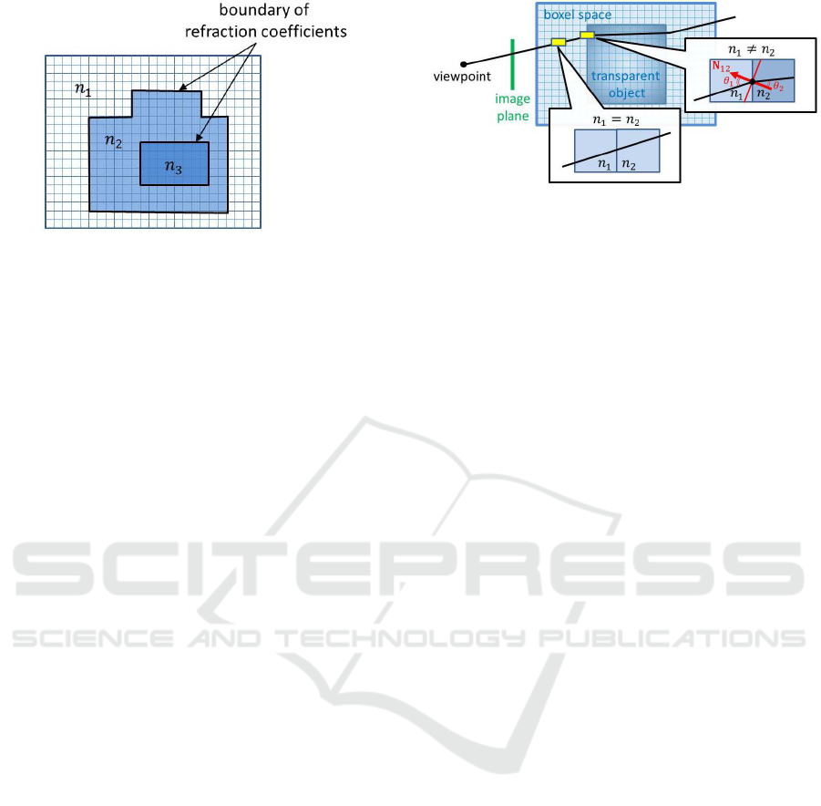
Figure 1: Boxel space and the boundary of transparent ob-
jects. All the boxels in the boxel space have their own re-
fraction coefficients, such as n
1
, n
2
and n
3
. The bound-
aries of these refraction coefficients can be considered as
the boundaries of transparent objects.
2 BOXEL SPACE FOR
TRANSPARENT OBJECTS
For recovering multilayer transparent objects, we in
this paper consider a boxel space with transparent
coefficients and surface normals. Each boxel in the
boxel space has a refraction coefficient n, and each
boundary of a pair of adjacent boxels has a surface
normal N.
Suppose we have a 3D boxel space, which con-
sists of N boxels b
i
(i = 1, ··· , N). Since each boxel is
a cube, there exist boundaries in X,Y and Z directions
at each boxel. The total number of boundaries is de-
noted by M. Let n
i
be a refraction coefficient of boxel
b
i
, and Let N
ij
be a surface normal at the boundary of
two boxels, b
i
and b
j
.
If we have a set of boxels which have homoge-
neous refraction coefficients and are connecting to
each other, the set of boxels can be considered as a
single transparent object, and the boundary of two ho-
mogeneous sets of boxels can be considered as the
boundary of two transparent objects.
Even if we have a multilayer transparent object,
it can be represented by a multilayer structure of ho-
mogeneous refraction coefficients in the boxel space.
Thus, this new representation of transparent objects is
very useful for representing complex multilayer struc-
tures of transparent objects.
3 REFRACTION OF LIGHT RAYS
IN THE BOXELS SPACE
We next consider refraction of light rays in the boxel
space. Since the boxel space is the quantization of
Figure 2: Refraction of light ray in the boxel space.
a 3D space, the refraction of light rays in the boxel
space is also quantized according to the boxel.
Suppose a light ray comes into a boxel b
2
from a
boxel b
1
as shown in Fig. 2. If the refraction coeffi-
cients of these two boxels are identical to each other,
i.e. n
1
= n
2
, then the light ray is not refracted at the
boundary of these two boxels.
However, if n
1
and n
2
are different from each
other, i.e. n
1
6= n
2
, the light ray is refracted at the
boundary of these two boxels according to the refrac-
tion coefficients, n
1
and n
2
, and the surface normal
N
12
as shown in Fig. 2.
This refraction can be described by the Snell’s law
as follows:
n
1
sinθ
1
= n
2
sinθ
2
(1)
where, θ
1
and θ
2
denote angles between the sur-
face normal N
12
and light rays before and after the
refraction.
Since these light rays and the surface normal are
coplanar in the 3D space, Eq.(1) can be rewritten as
follows:
n
1
(V
1
× N
12
) = n
2
(V
2
× N
12
) (2)
where, V
1
and V
2
denote unit vectors, which rep-
resent the direction of light rays before and after the
refraction respectively.
In this research we consider Eq.(2) at all the
boundary of boxels in the boxel space. Hence, all the
boxels have possibilities to refract light rays depend-
ing on the difference of refraction coefficients with
adjacent boxels. In the next section, we describe a
method for estimating the refraction coefficient and
the surface normal of these boxels.
4 ESTIMATING REFRACTION
COEFFICIENT AND SURFACE
NORMAL OF BOXELS
We next consider a method for estimating the refrac-
tion coefficient of each boxel and the surface normal
at each boundary in the boxel space. Our method is
VISAPP 2017 - International Conference on Computer Vision Theory and Applications
524
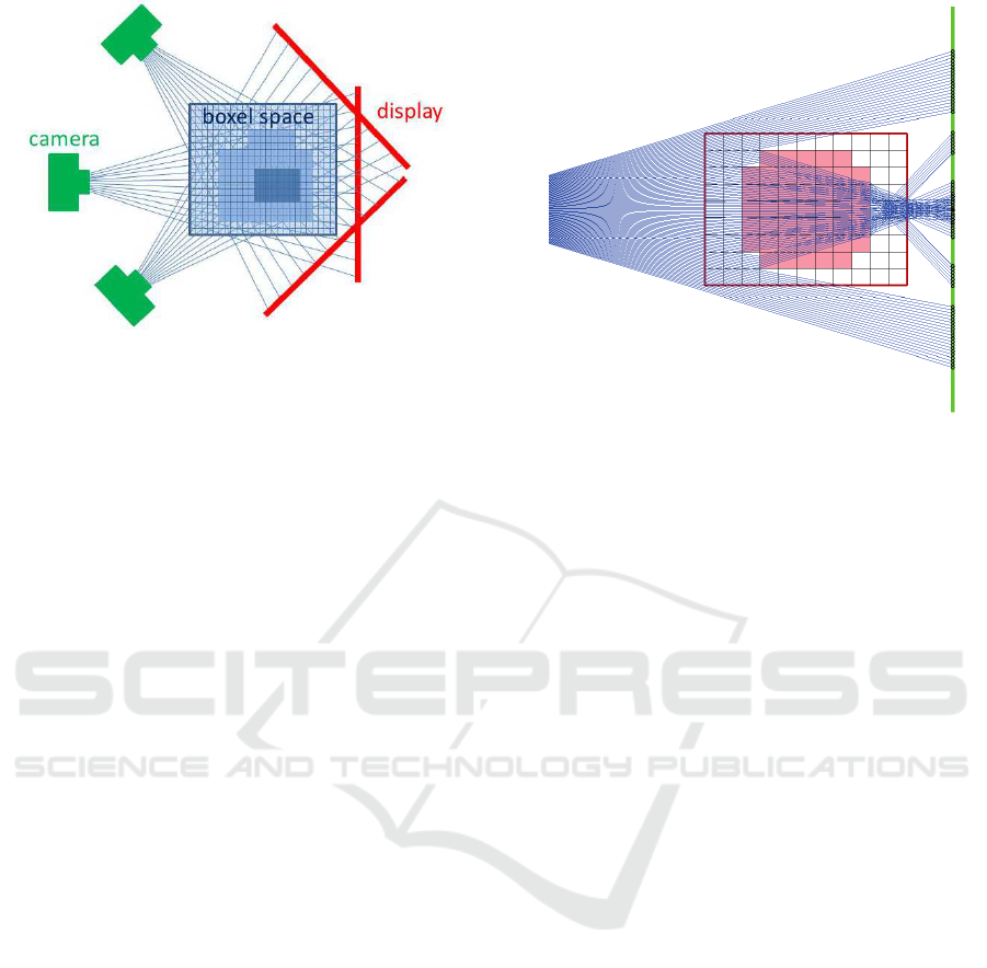
Figure 3: Multiple observations of the boxel space.
based on the rendering of hypothetic images and their
comparison with real observations.
The image D is shown by a display and is ob-
served by a camera through the transparent objects in
the boxel space. The image intensity of ith pixel of
the observed image I is denoted by I
i
. Now, we ren-
der a hypotheticimage R(n, S) from the display image
D based on the estimated refraction coefficients n =
[n
1
, ··· , n
N
] and surface normals S = [N
1
, ··· , N
M
],
where N
j
denotes the jth surface normal. We use the
ray tracing method for rendering images. The image
intensity of ith pixel of the rendered image R(n, S)
is denoted by R
i
(n, S). Then, we can define the fol-
lowing cost function E
1
for evaluating the accuracy of
rendered images.
E
1
=
P
∑
i=1
(R
i
(n, S) − I
i
)
2
(3)
where, P is the number of image pixels. If the es-
timated refraction coefficients n and the surface nor-
mals S are correct, the cost function E
1
is equal to zero
except the quantization error of boxel space. Thus, by
estimating n and S which minimize E
1
, we can obtain
the refraction coefficients and the surface normals of
the boxel space.
For obtaining the coefficients and normals of all
the boxels from Eq.(3), we need at least N + 2M mea-
surements, since we have N coefficients and M nor-
mals with 2 DOF. Thus the following inequality must
hold:
P ≥ N + 2M (4)
However, N + 2M is quite large in general, and it is
not easy to satisfy Eq.(4) just from a single image ob-
servation. Furthermore, the light rays observed at a
single viewpoint do not pass all the boxels in gen-
eral, while the light rays must pass all the boxels for
estimating the coefficients of all boxels. Thus, we
observe the boxel space from several different view-
points.
Figure 4: Our experimental set up. A single transparent
object exists in a 11 × 9 boxel space. The light rays are
refracted at the boundary of boxels according to refraction
coefficients n
i
and surface normals N
j
.
To make the observation more efficient, we rotate
the boxel space, i.e. transparent object, which is put
between the display and the camera, or rotate the dis-
play with a camera around the boxel space as shown
in Fig. 3. By rotating the boxel space relative to the
camera, and observing the boxel space from V dif-
ferent viewpoints, we can define the following cost
function:
E
2
=
V
∑
k=1
P
∑
i=1
(R
k
i
(n, S) − I
k
i
)
2
(5)
where, R
k
i
denotes the image intensity of ith pixel of
the rendered image at kth viewpoint, and I
k
i
denotes
the image intensity of ith pixel of the observed im-
age at kth viewpoint. By estimating n and S which
minimize E
2
, we can obtain the refraction coefficients
and the surface normals of all the boxels in the boxel
space.
In this case, the coefficients and normals of all the
boxels can be estimated, if the following inequality
holds:
PV ≥ N + 2M (6)
For raising the stability of estimation, we also intro-
duce a regularization term on the smoothness of ob-
ject shape as follows:
E
3
=
V
∑
k=1
P
∑
i=1
(R
k
i
(n, S) − I
k
i
)
2
+ λ
M
∑
j=1
|∆N
j
|
2
(7)
where, ∆N
j
denotes the variation of N
j
in X, Y
and Z directions in the boxel space, and | · |
2
denotes
an L
2
norm. In the end, we estimate n and S which
minimize E
3
.
Recovering 3D Structure of Multilayer Transparent Objects from Multi-view Ray Tracing
525
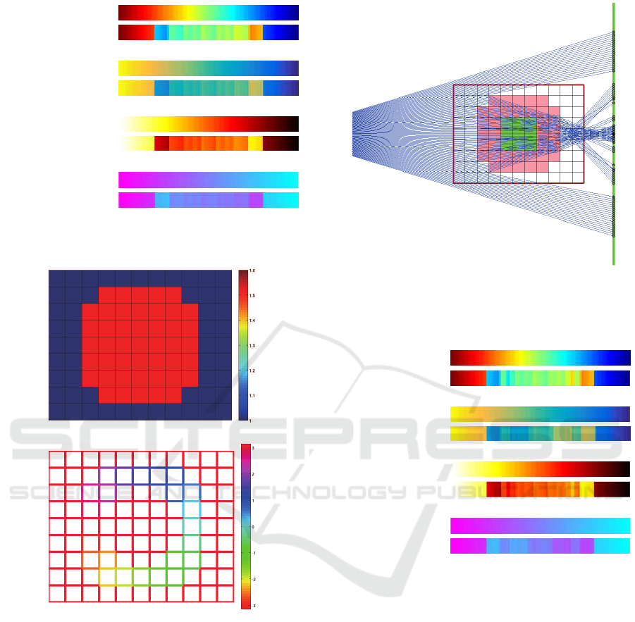
displayed image
observed image
(a) 1st viewpoint
displayed image
observed image
(b) 2nd viewpoint
displayed image
observed image
(c) 3rd viewpoint
displayed image
observed image
(d) 4th viewpoint
Figure 5: Displayed images and observed images through a
transparent object at 4 different viewpoints.
(a) refraction coefficients
(b) surface normals
Figure 6: The refraction coefficients and surface normals
estimated from the proposed method. The color bars on
the right show the measures of refraction coefficients and
surface normals. The unit of the surface normals is radian.
Since the proposed method enables us to estimate
all the refraction coefficients in the 3D space, com-
plex transparent objects with multiple layers can be
reconstructed.
5 EXPERIMENTS
We next show the efficiency of the proposed method
from synthetic image experiments. In this experi-
ment, we synthesized camera images of multilayer
Figure 7: Our experimental set up. Multilayer transparent
objects exist in a 11 × 9 boxel space. The light rays are
refracted at the boundary of boxels according to refraction
coefficients n
i
and surface normals N
j
.
displayed image
observed image
(a) 1st viewpoint
displayed image
observed image
(b) 2nd viewpoint
displayed image
observed image
(c) 3rd viewpoint
displayed image
observed image
(d) 4th viewpoint
Figure 8: Displayed images and observed images through a
transparent object at 4 different viewpoints.
transparent objects as well as a single transparent ob-
ject viewed from several different viewpoints, and
used these images for recovering the structure of the
transparent objects by using the proposed method.
For simplifying our experiments, we in this paper
consider a 2D space, and project the 2D space into
a 1D camera.
Fig. 4 shows our experimental setup, in which a
transparent disk exists in a 11×9boxel space. The 1D
image on a display is observed through the transpar-
ent disk by a 1D camera with 100 pixels. The object is
rotated and observed from 4 different viewpoints. The
displayed image and an observed image are shown in
Fig. 5. The refraction coefficients and the surface nor-
mal of the boxel space are computed from these ob-
served images by using the proposed method. The
VISAPP 2017 - International Conference on Computer Vision Theory and Applications
526
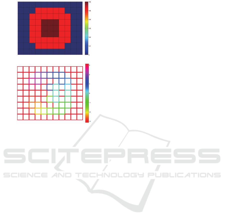
(a) refraction coefficients
(b) surface normals
Figure 9: The refraction coefficients and surface normals
estimated from the proposed method. The color bars on
the right show the measures of refraction coefficients and
surface normals. The unit of the surface normals is radian.
estimated refraction coefficients and the surface nor-
mals of all the boxels are shown in Fig. 6. As shown
in this figure, the boundary of the refraction coeffi-
cients in the boxel space coincide with the original
shape of the transparent object shown in Fig. 4, and
we find that the structure of the transparent object can
be recovered by using the proposed method.
We next show the results from multilayer trans-
parent objects shown in Fig. 7. The observed images
are shown in Fig. 8, and the refraction coefficientsand
surface normals recovered from the proposed method
is shown in Fig. 9. As shown in Fig. 9, the estimated
refraction coefficients represent the complex structure
of the original multilayer transparent object shown in
Fig. 7.
Although the experimental results are still limited,
they show that the proposed method can recover com-
plex multilayer structure of transparent objects.
6 CONCLUSION
In this paper, we proposed a method for recovering
the 3D structure of multilayer transparent objects. For
this objective we introduced a new representation of
3D space by using boxel space with refraction prop-
erties and surface normals. Based on the new repre-
sentation of 3D space, we proposed a method for re-
covering the refraction properties and surface normals
of all the boxels in the boxel space. The efficiency of
the proposed method was shown by some preliminary
experiments.
REFERENCES
Agarwal, S., Snavely, N., Simon, I., Seitz, S., and Szeliski,
R. (2009). Building rome in a day. In Proc. ICCV.
Ding, Y., Li, F., Ji, Y., and Yu, J. (2011). Dynamic fluid sur-
face acquisition using a camera array. In Proc. ICCV.
Heinly, J., Schonberger, J., Dunn, E., and Frahm, J. (2015).
Reconstructing the world in six days. In Proc. Con-
ference on Computer Vision and Pattern Recognition,
pages 3287–3295.
Miyazaki, D. and Ikeuchi, K. (2007). Shape estimation of
transparent objects by using inverse polarization ray
tracing. Trans. PAMI, pages 2018?–2030.
Qian, Y., Gong, G., and Yang, Y. (2016). 3d reconstruc-
tion of transparent objects with position-normal con-
sistency. In Proc. Conference on Computer Vision and
Pattern Recognition.
Shan, Q., Agarwal, S., and Curless, B. (2012). Refractive
height fields from single and multiple images. In Proc.
Conference on Computer Vision and Pattern Recogni-
tion.
Tsai, C., Veeraraghavan, A., and Sankaranarayanan, A.
(2015). What does a light ray reveal about a trans-
parent object? In Proc. ICIP.
Wetzstein, G., Roodnick, D., Heidrich, W., and Raskar, R.
(2011). Refractive shape from light field distortion. In
Proc. ICCV.
Recovering 3D Structure of Multilayer Transparent Objects from Multi-view Ray Tracing
527
