
High Brightness Multi-Mode Fiber Lasers
A Novel Sources for in-Band Cladding Pumping of Singlemode Fiber Lasers
Leonid V. Kotov
1*
, Oleg I. Medvedkov
1
, Mikhail M. Bubnov
1
, Denis S. Lipatov
2
,
Aleksei N. Guryanov
2
and Mikhail E. Likhachev
1
1
Fiber Optics Research Center of the Russian Academy of Science, 38 Vavilov Street, Moscow 119333, Russia
*
Now with College of Optical Sciences, University of Arizona, 1630 East University Blvd., Tucson, Arizona 85721, U.S.A.
2
Institute of Chemistry of High Purity Substances RAS, 49 Tropinina street, Nizhny Novgorod 603950, Russia
Keywords: Multi-Mode Laser, Er-doped Fiber, in-Band Pumping, High-Power Laser, High-Brightness Pump.
Abstract: A novel design of multi-mode Er-doped fiber lasers operated in the spectral region of 1530-1600 nm have
been proposed and realized. The lasers efficiency exceed 35-42% (depending on the wavelength), while
maximum output power is limited on the level of 60 W only by pump power available in the experiment. The
developed multi-mode laser can be used as an efficient high-power and high-brightness pump source for Er-
doped (pump at 1530-1535 nm) and Tm-doped (pump at 1560-1600 nm) singlemode fiber lasers. Utilization
of the same concept to the Yb-doped lasers could strongly accelerate output power growth of single-mode
lasers in the 1 µm region as well.
1 INTRODUCTION
Resonant pumping is a promising approach in a
development of kW-level single-mode fiber lasers. A
small quantum defect allows one to obtain a high
pump-to-signal conversion efficiency and, thus, to
reduce a thermal load on an active fiber. There is a
strong need in efficient and high-power sources at
1010-1040 nm for in-band pumping of Yb-doped
lasers; at 1530-1535 nm – for pumping of Er-doped
and at 1560-1600 nm – for Tm-doped fiber lasers
(Zhang J., 2011; Jebali M.A., 2014).
However development of such sources is a
challenging task by itself. For 1530-1535 nm spectral
region (pump of Er-doped fiber lasers) a multi-mode
semiconductor diode can be used. However, to the
moment price, available power and electrical-to-
optical efficiency of multimode diodes at 1532 nm
significantly inferior to that of well-developed pump
diodes at 980 nm. Another problem of such diodes is
a thermal drift of central wavelength. The thing is in
rather small (several nm) width of erbium absorption
peak near 1532 nm. So, wavelength change with
power can lead to decrease of pump absorption and
efficiency rollover. Moreover, high power
semiconductor diodes for longer wavelengths (1560-
1600 nm) are not available at all.
Another option to build 1530-1600 nm pump laser
is combining of several single-mode Er-Yb fiber
lasers which in turn are pumped by 9XX diodes
(Jebali M.A., 2014). However, output power of lasers
based on commercially available single-mode Er-Yb
fibers is limited by Yb emission near 1 µm at ~10 W
level (Sobon G., 2014). So, although such pump
source provides great wavelength stability and
efficiency, it requires huge number of Er-Yb lasers
(36 in ref. (Jebali M.A., 2014)) that significantly
increase cost of the laser.
Development of pump sources operated in the
spectral region near 1010-1040 nm is also not an easy
task. Absence of efficient pump diodes in this region
requires utilization of Yb-fiber lasers operated at this
wavelength. However a specially developed large
core-to-cladding ratio fibers are required to achieve a
high inversion (to get a non-zero gain) and reasonable
efficiency (Aleshkina S.S., Likhachev M.E., 2016).
The goal of our work is the development of
compact and cheap pump source for in-band pumping
of single-mode fiber lasers. The current
communication is focused on the development of
multi-mode Er-doped lasers for 1.5 µm region.
However, we suggest that the same principles could
be used for building of multi-mode pump source near
1 µm spectral range for in-band pumping of Yb-
doped lasers.
Kotov L., Medvedkov O., Bubnov M., Lipatov D., Guryanov A. and Likhachev M.
High Brightness Multi-Mode Fiber Lasers - A Novel Sources for in-Band Cladding Pumping of Singlemode Fiber Lasers.
DOI: 10.5220/0006166800990105
In Proceedings of the 5th International Conference on Photonics, Optics and Laser Technology (PHOTOPTICS 2017), pages 99-105
ISBN: 978-989-758-223-3
Copyright
c
2017 by SCITEPRESS – Science and Technology Publications, Lda. All rights reserved
99
2 DESIGN OF THE PUMP LASER
2.1 Er-doped Multimode Fiber
As mentioned above, the output power of a laser at
15XX nm based on commercially available single-
mode Er-Yb co-doped fiber is limited by parasitic
lasing near 1 µm. A solution to this problem could be
the utilization of Yb-free Er-doped double clad fiber
as the active media for high power pump lasers near
1532-1535 nm (for Er-doped fiber lasers) or 1560-
1600 nm (for Tm-doped fiber lasers). It was shown
recently that such fibers are able to demonstrate
optical-to-optical efficiencies up to 40% when
pumped at 980 nm (Kotov L.V., 2013. Opt. Lett.).
However, special design of these fibers is required.
This design includes a large core diameter to provide
high pump absorption, an optimized core
composition (including low concentration of Er
3+
ions) to suppress clustering. A fiber with a core
diameter of 35 µm was proposed and realized in
(Kotov L.V., 2013. Opt. Lett.). This core size was
limited by the requirements of single mode operation
and reasonably low bending loss. The maximum
slope efficiency demonstrated with this fiber was
40 % and was achieved at an operation wavelength of
1585 nm. This source is suitable for pumping Tm-
doped fiber lasers, but the long fiber length (~40 m)
and a relatively high bend sensitivity (fiber should be
wounded on a spool with 30 cm diameter) makes it
rather cumbersome. Moreover the influence of
clustering became much stronger for shorter
wavelengths and results in a reduction of the
efficiency down to 15 % near 1532 nm
(ICONO/LAT). Thus, such lasers are not applicable
for efficient pumping of the Er-doped single-mode
fiber lasers.
On the other hand, there is no need for a high
beam quality of the cladding pump for singlemode
fiber lasers. The parameters of the fiber core are
limited only by the requirement to match them to the
pump ports of standard pump combiners:
core/cladding diameters of 105/125 µm and
numerical apertures (NA) of 0.15. Therefore, the
active fiber core could be multimode and has
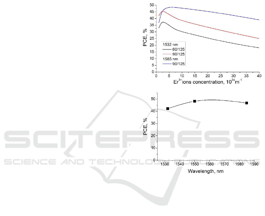
diameter up to 105 µm. We performed a numerical
analysis similar to (Kotov L.V., 2013. Opt. Lett.) to
define the optimum erbium concentration. The signal
grey loss was taken to be about 5 dB/km, pump loss
– to be about 20 dB/km. The pump-to-signal slope
conversion efficiency (PCE) of the amplifier based on
co-propagating pump and signal power based on
60/125 µm and 90/125 double-clad Er-doped fibers
operating at 1535 nm and 1585 nm were computed
(Fig 1a). An efficiency of about 45% for signal at
1532 nm and 47% for signal at 1585 nm could be
achieved. Wavelength dependence of maximum
pump-to-signal conversion efficiency (PCE) is rather
weak near the optimal concentration (see Fig.1b) and
its maximum lies near 1565 nm wavelength.
Figure 1: a - Computed pump-to-signal slope conversion
efficiency (PCE) of the amplifier at 1532 nm and at 1585
nm for different Er
3+
ions concentration and core/clad ratio;
b – PCE dependence on wavelength for Er concentration
about 710
24
m
-3
and core/clad ratio as 105/125 µm.
Based on the simulation results, a fiber preform
with aluminosilicate core and ~4∙10
24
m
-3
Er
3+
ions
concentration was produced using the Modified
Chemical Vapor Deposition (MCVD) technique. The
preform was polished to an octagonal shape and
double clad fiber was drawn down from it. The
resulting fiber has core/cladding diameters
of95/125 µm and was coated with polymer providing
a pump NA of 0.46. Microscope image of the fiber
facet is presented in Fig.2a. The refractive index
profile (RIP) of the fabricated MCVD preform is
presented in Fig. 2b. The core grey loss at 1200 nm
was measured to be about 35 dB/km.
a
b
PHOTOPTICS 2017 - 5th International Conference on Photonics, Optics and Laser Technology
100
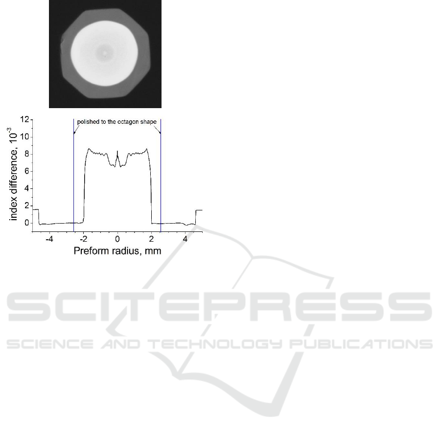
Figure 2: a - Microscope image of the fiber facet; b -
Refractive index profile of the fabricated Er-doped preform.
2.2 Multi-mode Er-doped Fiber
Amplifier at 1565 nm
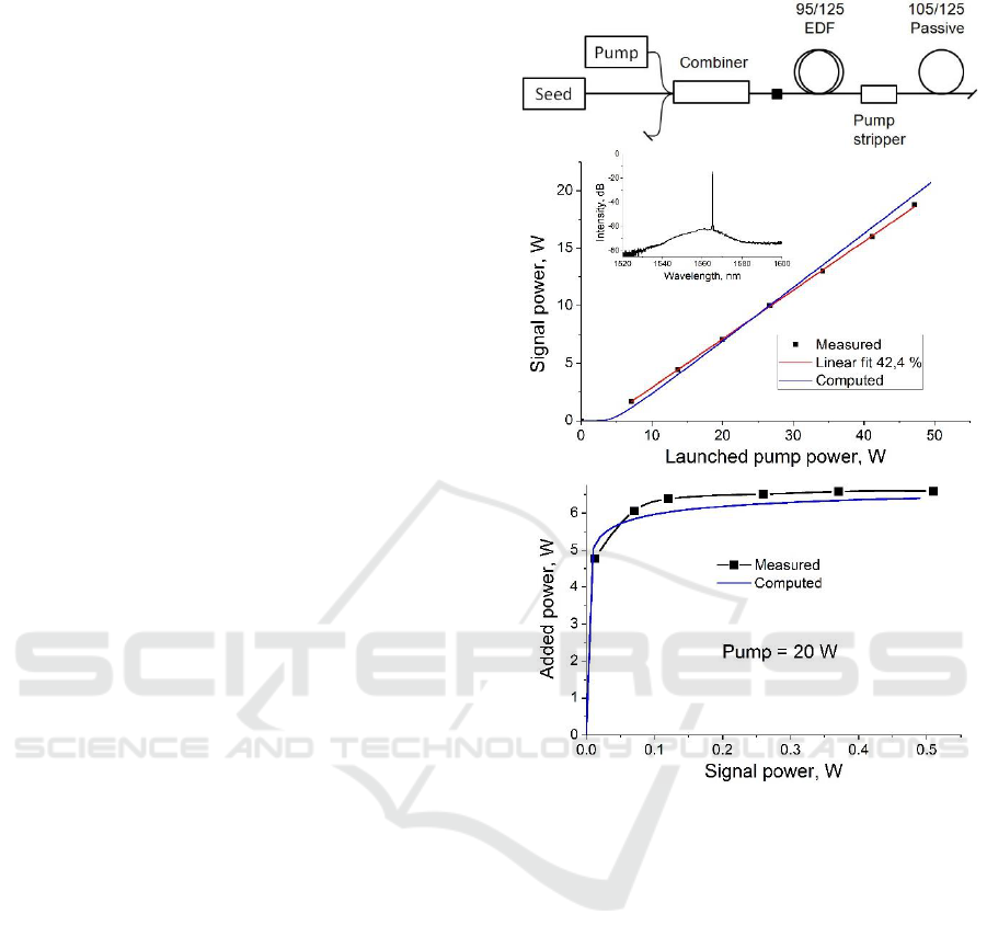
At first the developed multi-mode Er-doped fiber was
tested in a simple amplifier scheme, shown in Fig.3a.
The standard 2+1-to-1 pump and signal combiner was
used to deliver signal and pump into the Er-doped
fiber. Signal fiber was standard single-mode 8/125
µm double clad fiber. The pump ports were based on
standard 105/125 µm fiber. The pump module has
maximum pump power of 50 W and it wavelength
was stabilized at 976±0.5 nm by an internal volume
Bragg grating. The pump combiner output was
spliced to the developed multi-mode Er-doped fiber.
The multi-mode fiber output was spliced to a standard
multi-mode 105/125 µm fiber. A pump stripper
similar to the described in (Aleshkina S., Kochergina
T.A., 2016) was built at the splice point.
Our calculations has shown that the developed
amplifier has the maximum efficiency when operates
near 1565 nm. An Er-Yb laser with maximum output
power of 0.5 W (limited by available isolator) was
used as a seed source. The length of multi-mode Er-
doped fiber was about 16.7 m that is close to the
optimal one (according to our calculations).
Dependence of output power at 1565 nm on pump
power at 976nm is shown in Fig.3b. The dependence
of output power on input signal (see Fig.3c) shows
that the multi-mode fiber operated in saturation
regime. Both dependences are fairly close to those,
calculated using model and data (i.e. clustering level)
from (Kotov L.V., 2013. Opt. Lett.) and actual
parameters of the developed multi-mode fiber
(core/clad diameters, Er-concentration and grey loss).
The slope pump-to signal conversion efficiency was
found to be as high as 42.4%, which is the highest
ever reported value for high-power Er-doped fiber
lasers pumped at 980 nm. It is still below the
predicted maximum PCE (see Fig.1), which is caused
by increase of grey loss from 5 to 35 dB/km. We
suggest that improvement in preform production
process would result in further increase for the PCE
in the developed multi-mode fiber amplifier.
2.3 Multi-mode Pump Laser at 1535
nm
In addition to a high efficiency, there are other
important demands for the pump source:
compactness, high long-term stability, small size and
low cost. The amplifier scheme presented in previous
paragraph is quite efficient, but it requires operation
of additional seed laser. Presence of the seed laser that
is powerful enough to saturate the amplifier increases
the cost and footprint of the system and makes it more
cumbersome. Moreover, even in saturated regime the
back-reflected signal can strongly affect the amplifier
– a significant signal power might propagate in the
backward direction in this case. Thus, it is preferable
to keep power of the seed laser to be on the level of
4-10% of the output power to ensure a safe operation
regime. When output power would grows to the level
of 100 and even 200 W (see discussion section) the
required seed laser power would exceed limit that is
possible to achieve with Er-Yb lasers. By this reason
in this section we propose a new laser design, free
from aforementioned drawbacks.
The simplest and, therefore, the cheapest scheme
for a fiber laser consists of a gain fiber spliced
between two fiber Bragg gratings (FBGs). However,
it is known that different modes have different
reflection spectra from FBG written in multimode
fiber. As a result, the spectrum of such a multimode
laser has several peaks (Kurkov A.S., 2007), leading
to effective spectral broadening. In addition, this
effect could result in unstable operation because of
mode competition. To ensure a narrow spectrum of a
multimode laser, a master oscillator power amplifier
(MOPA) scheme could be used.
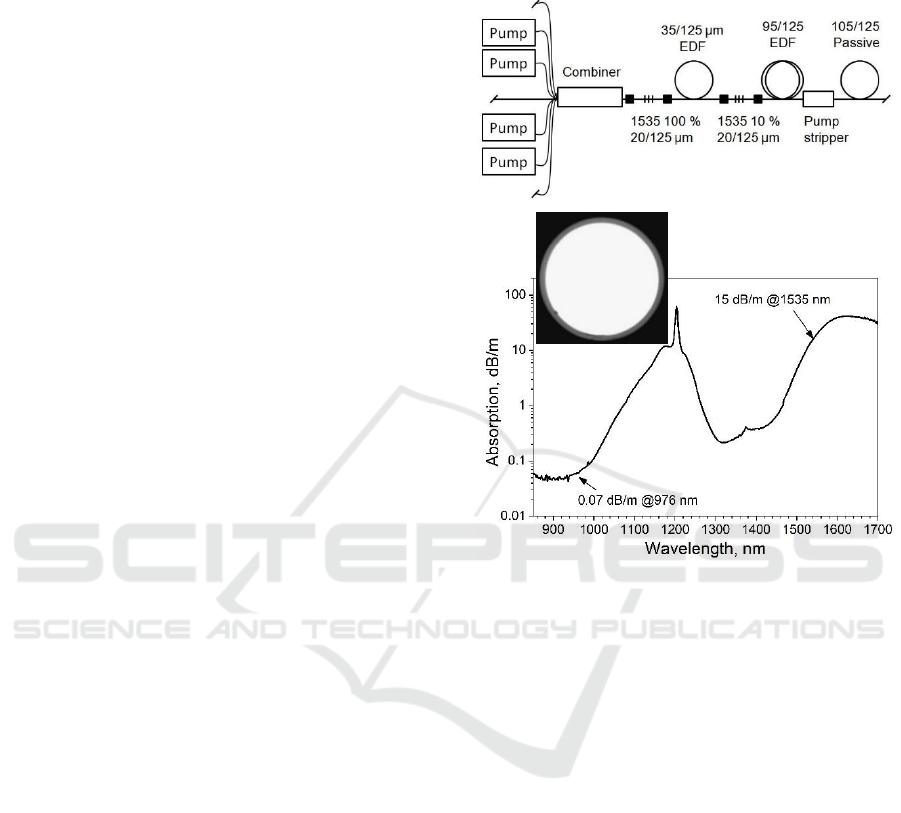
In this work, we propose the new, simple
multimode laser scheme shown in Fig. 4 a. A pump at
a
b
High Brightness Multi-Mode Fiber Lasers - A Novel Sources for in-Band Cladding Pumping of Singlemode Fiber Lasers
101
980 nm was launched into the cavity formed by 1.5 m
of the single-mode double clad EDF developed in
(Kotov L.V., 2013. Opt. Lett.) and a pair of FBGs.
Four multimode pump diodes with an operation
wavelength stabilized at 976 nm and overall
maximum power of 173 W were coupled through a
commercially available 7x1 pump combiner into the
laser resonator. The FBGs were written in 20/125
passive fiber (NA~0.08/0.45) and had reflections of
~100 % and 10 % at 1535 nm with bandwidths <0.8
nm. The small-signal absorption from the cladding
near 980 nm of the single-mode EDF is ~0.6 dB/m
(Kotov L.V., 2013. Opt. Lett.), so only ~5 % of the
overall pump power was absorbed in the single-mode
laser cavity. It generated light at 1535 nm with a slope
efficiency of ~45 % with respect to the absorbed
power. This signal was used as the seed radiation for
the 12 m piece of multimode EDF described above
that was spliced to the 10 % FBG of the single-mode
cavity. Commercially available 105/125 µm
multimode fiber was spliced at the output of the laser,
and a cladding pump stripper similar to that described
in (Aleshkina S., Kochergina T.A., 2016) was built at
the splice point. Therefore, the seed laser and
amplifier were both pumped by the same pump
diodes at 976 nm, and the spectral width of the laser
was locked by the FBGs written in the single mode
fiber, resulting in a relatively narrow output spectrum.
A specially developed multimode Tm-doped fiber
was produced using the MCVD technique in order to
protect the pump diodes from possible backward
radiation near 1.5 µm. The fiber had a Tm-doped
germanosilicate core and pure silica cladding with
diameters of 105/125 µm and NA~0.22 (see insert to
Fig4b). Thus, this fiber was matched to standard
multimode pump fibers. The fiber loss was measured
to be ~15 dB/m at 1535 nm and <70 dB/km at 976 nm
(see Fog.4b). Two meter pieces of the Tm-doped fiber
were spliced to each pump diode (not shown in Fig. 4
a). Due to the low feedback, large core diameter and
long length of the Tm-doped fibers, the threshold for
2 µm lasing was orders of magnitude higher than the
power of the potential back-propagating signal.
Therefore, this signal would only be absorbed by the
Tm ions and converted into spontaneous
luminescence and heat. Thus, the developed Tm-
doped fiber is an efficient pump protector for high
power systems operating near 1.55 µm and pumped
at 980 nm.
Fig. 5 a shows the output power of the developed
multimode laser; 60 W of output power, which was
limited by the available pump power, was achieved.
The slope efficiency of the laser was estimated to be
35 %. The output spectrum measured over all spectral
Figure 3: a - Scheme of the multi-mode Er-doped fiber
amplifier; b – Dependence of the output power at 1565 nm
on pump power, insert – output spectrum; c - Dependence
of output power on input signal power at 1565 nm (pump
power was fixed at 20 W). Blue lines – calculations,
symbols – measurements.
range with 0.5 nm resolution is presented in the Fig.
5 b. A small part (~8 % relative to the output power
of the laser) of unabsorbed pump at 976 nm was
propagated in the multimode laser core together with
the signal near 1535 nm. No active cooling was
applied to the EDF during operation. Short-term
temporal stability was investigated using a
photodetector. A stable cw operation without self-
pulsing was found (see Fig.5 c). Typical for all CW
lasers noise on the time trace was caused by
interference of different modes within 0.5 nm spectral
bandwidth.
b
c
a
PHOTOPTICS 2017 - 5th International Conference on Photonics, Optics and Laser Technology
102
3 DISCUSSION
This work is devoted to a new concept of a multimode
pump laser which could be used for in-band pumping
of single-mode fiber lasers. Highly efficient operation
is demonstrated for 1565 nm signal wavelength
(suitable for pumping of Tm-doped fiber lasers) and
for 1535 nm signal wavelength (suitable for pumping
of Er-doped fiber lasers). An output power of 60 W at
1535 nm was achieved with a slope efficiency of 35
% with respect to the launched pump power at 976
nm. Taking into account the electrical-to-optical
efficiency of the diodes at 980 nm (50 %), the overall
"wall-plug" efficiency of the developed laser is ~17.5
%, which is fairly close to that of multimode diodes
operating in this spectral region (25 %). Meanwhile,
there are two serious advantages of the developed
source over semiconductor pump diodes:
First, it has perfect output wavelength
stabilization. The laser scheme includes FBGs written
into single-mode fiber as a wavelength-stabilizing
element. For this reason, the multimode fiber laser
operates with a narrow bandwidth (~0.5 nm) at the
chosen central wavelength independent of the output
power. At the same time, thermal drift and a broad
output spectrum are well-known problems of high
power semiconductor diodes.
Second, the demonstrated power of 60 W is
already higher than the values that could be found
from commercially available multimode diodes at
1535 nm with 105/125 µm output fibers (typically ~
30 W). The demonstrated output power is guided by
the core with diameter of 105 µm and NA of 0.15. To
the best of our knowledge obtained brightness of
7.6610
4
W/mm
2
sr is the highest ever reported
brightness for this spectral region.
Also it should be stressed that power of the
proposed multi-mode fiber laser could be easy scaled.
Indeed, only four of seven pump ports of the laser
were utilized in the experiment. This means that using
three additional pump diodes at 976 nm with the same
power level it is possible to increase output power to
more than 100 W power level. Moreover a 100 W
multimode pump diode sources at 976 nm with
105/125 µm fiber pigtail are commercially available.
Thus, the utilization of 7 of them and a 7 to 1 pump
combiner allows one to achieve more than 200 W at
1535 nm from 105/125 fiber with NA=0.15 at the
output of the multimode laser. Finally even this
output power level from multi-mode fiber laser is not
limited. As it was seen in Fig.1a the decrease of PCE
is not very significant for Er-doped multi-mode fiber
with core-to-clad ratio about 0.5 (60/125 µm). This
means that multi-mode Er-doped fiber with core and
clad equal to 100 and 200 µm could be realized and
its PCE can be equal to 35% (same as in
Figure 4: a - Scheme of the multi-mode Er-doped fiber
laser; b – Absorption in the Tm-doped 105/125 µm fiber,
used as pump protector; insert: Tm-doped fiber cross
section.
current laser) if the fiber grey loss are optimized.
Currently pump combiners with 19 pump ports
(105/125 µm, NA=0.15) and output into fiber with
outer diameter of 200 µm and NA=0.45 are
commercially available. This means that there are no
fundamental limitation to scale output power of
multi-mode lasers at 1530-1590 nm (output inside
105/125 µm fiber with NA=0.15) to the level of 600
W of output power.
Utilization of such powerful pump sources instead
of semiconductor pump diodes (Zhang J., 2011) or
Er-Yb fiber lasers (Jebali M.A., 2014) could be very
promising. In particular using of 7+1-to1 pump
combiner and 7 such pump sources with a highly
efficient in-band pumped Er-doped fiber laser (up to
75% PCE was demonstrated in (Jebali M.A., 2014))
could allow one to scale output power of the single-
mode laser to the unprecedented level of more than 3
kW.
Same pump and laser design could be utilized for
Tm-doped fiber lasers. Moreover a higher
demonstrated PCE for the multi-mode Er-doped
a
b
High Brightness Multi-Mode Fiber Lasers - A Novel Sources for in-Band Cladding Pumping of Singlemode Fiber Lasers
103
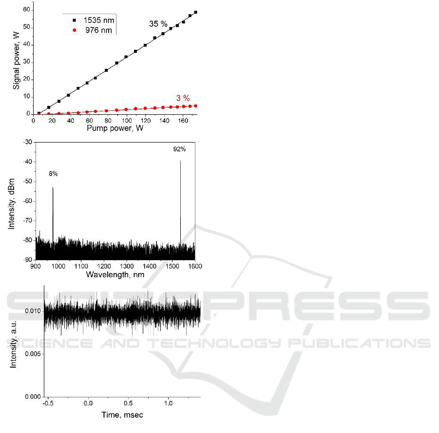
Figure 5: a – Dependence of the output power at 1535 nm
and unabsorbed pump on pump power at 976 nm, b –
Typical spectrum at the laser output, c – time trace from
photodetector.
fiber laser operated at 1565 nm (42.4%) simplify
power scaling to even higher level. Simple utilization
of seven 100 W semiconductor lasers at 976 nm
would allow one to achieve near 300 W output pump
level. Optimization of parameters of Er-doped fiber
with core and cladding diameters of 100 µm and 200
µm should allow one to increase output power to 800
W. A high in-band PCE efficiency of Tm-doped
lasers (70% in (Shen D.Y., Sahu J.K., and Clarkson
W.A., 2006)) can allow power scaling to almost 4 kW
level.
Finally the power scaling of Yb-doped fiber lasers
looks most promising with such laser design. In this
case utilization of 100/400µm multi-mode Yb-doped
fiber could allow one to realize few-kW multi-mode
pump sources near 1.01-1.04 µm. In its turn
utilization of such source to pump fiber laser, based
on a perfectly single-mode (10..15)/(200..400) µm
fiber can allow one scale output power of single-
mode Yb-doped lasers to over 10 kW.
4 CONCLUSIONS
In conclusion, a simple, cheap and efficient scheme
of the pump multimode laser has been proposed and
realized. PCE of 35-42 % and output power up to
60 W was demonstrated with realized lasers schemes.
Simple power scalability of such pump source is
discussed. A new approach for the development of
high-power, in-band pumped, single-mode fiber
lasers is presented. Thanks to the easy power
scalability of the developed system, few kWs-level
single-mode Er-doped and Tm-doped fiber lasers
near 1.55 µm could be realized in the near future.
Possibility to apply the same laser concepts for the
Yb-doped fiber lasers and scale output power of
single-mode lasers to beyond 10 kW are also
indicated.
ACKNOWLEDGEMENTS
This work was supported by grant 16-12-10553 from
the Russian Science Foundation. The authors are
grateful to E.M. Dianov, scientific supervisor of the
Fiber Optics Research Center for his continuous
interest in and support of this work.
REFERENCES
Zhang J., Fromzel V., and Dubinskii M., 2011. Resonantly
cladding-pumped Yb-free Er-doped LMA fiber laser
with record high power and efficiency, Opt. Express,
19, 5574-5578.
Jebali M.A., Maran J.-N., and LaRochelle S., 2014. 264 W
output power at 1585 nm in Er–Yb codoped fiber laser
using in-band pumping, Opt. Lett. 39, 3974-3977.
Sobon G., Sliwinska D., Abramski K.M. and Kaczmarek P.,
2014. 10 W single-mode Er/Yb co-doped all-fiber
amplifier with suppressed Yb-ASE, Laser Phys. Lett.
11, 025103.
Aleshkina S.S., Likhachev M.E., Lipatov D.S., Medvedkov
O.I., Bobkov K.K., Bubnov M.M., Guryanov A.N.,
2016. 5.5 W monolitic single-mode fiber laser and
a
b
c
PHOTOPTICS 2017 - 5th International Conference on Photonics, Optics and Laser Technology
104

amplifier operating near 976 nm, Proc. SPIE 9728,
Fiber Lasers XIII: Technology, Systems, and
Applications, 97281C (March 11);
doi:10.1117/12.2209610.
Kotov L.V., Likhachev M.E., Bubnov M.M., Medvedkov
O.I., Yashkov M.V., Guryanov A.N., Lhermite J.,
Fevrier S., and Cormier E., 2013. 75 W 40% efficiency
single-mode all-fiber erbium-doped laser cladding
pumped at 976 nm, Opt. Lett. 38, 2230-2232.
Kotov L., Likhachev M., Bubnov M., Medvedkov O.,
Yashkov M., Guryanov A., Fevrier S., Lhermite J.,
Cormier E., 2013. Optimization of double-clad Er-
doped fibers for high power highly efficient lasers and
amplifiers, ICONO/LAT 2013, paper LWF4.
Aleshkina S., Kochergina T.A., Bobkov K.K., Kotov L.V.,
Bubnov M.M., Park J., and Likhachev M.E., 2016.
High-Power 125-μm-Optical-Fiber Cladding Light
Stripper, in Conference on Lasers and Electro-Optics,
OSA Technical Digest (online) (Optical Society of
America, 2016), paper JTu5A.106.
Kurkov A.S., Paramonov V.M., Yashkov M.V., Goncharov
S.E. and Zalevskii I.D., 2007. Multimode cladding-
pumped erbium-doped fibre laser, Quantum Electron.
37(4), 343.
Shen D.Y., Sahu J.K., and Clarkson W.A., 2006. High-
power widely tunable Tm:fibre lasers pumped by an
Er,Yb co-doped fibre laser at 1.6µm, Opt. Express 14,
6084-6090.
High Brightness Multi-Mode Fiber Lasers - A Novel Sources for in-Band Cladding Pumping of Singlemode Fiber Lasers
105
