
New Co-design Methodology for Real-time Embedded Systems
Ines Ghribi
1,2
, Riadh Ben Abdallah
1
, Mohamed Khalgui
1
and Marco Platzner
3
1
LISI Laboratory, INSAT, University of Carthage, Tunis, Tunisia
2
Department of Computing science, University of Tunis el Manar, Tunis, Tunisia
3
Department of Computing science, University of Paderborn, Paderborn, Germany
Keywords: Co-design Methodology, Real-time Embedded Systems, Partitioning, Probabilistic Software.
Abstract: Over the years we are witnessing and ever increasing demand for functionality enhancements in the embedded
real-time systems. Along with functionalities, the design itself grows more complex. Posed constraints as
time, space bounds and energy consumption also require proper handling. In order to enhance the behaviour
of such systems, we have developed the I-codesign, a methodology for modelling, partitioning and simulating
embedded real-time systems. The tasks in this methodology are described with a probabilistic manner and
characterized with real-time parameters. A new partitioning technique aims at each of its three phases to
respect firstly the inclusion/exclusion parameters, secondly energy and memory constraints and finally
verifies real-time constraints. The output of I-codesign is an embedded controller that supervises the behaviour
of the executing system and schedule the implementation /configurations of the software.
1 INTRODUCTION
The complexity of designing embedded systems is
constantly increasing which motivates the need for
using more efficient tools and design methodologies.
Designing at a higher level of abstraction reduces
the number of components with which the designer
has to deal, and thus increasing design productivity.
This paradigm shift in design requires methodologies
and automated tools to support design at higher levels
abstractions (Pillai and Shin, 2001).
Hardware/software co-design is the technique of
designing concurrent hardware and software
components of an embedded system (Teich, 2012;
Cheng et al., 2011). Generally, hardware/software co-
design starts with specification then modeling the
system behavior at the system level (Wainer, 2013).
The hardware/software partitioning step follows. This
step is a combinational optimization problem that
assigns the system functions to the target architecture
on the software and hardware domain under the
condition of meeting the design constraints (Tang et
al., 2015). This is a key task in the system level
design, because the decisions made during this step
directly impact the performance and cost of the final
implementation. One of the main performances issues
in embedded systems design is to guarantee the
results within a given time (Banerjee et al.,2015;
Joshi and Gurumurthy, 2014). Such systems, which
have to fulfill posed constraints, are called realtime
systems (Pillai and Kang, 2001; Nikolic et al., 2011).
In these systems, time at which results of a
computation are available is crucial. Another
challenge in designing embedded systems is dealing
with reconfigurablility, since they have the apability
to modify their functionalities, to add or to remove
components and to modify interconnections among
them. The basic idea behind these systems is to have
a system that autonomously modifies its
functionalities according to the changing application
inputs (Wang et al., 2009). In (Ghribi et al., 2015), we
present a new technique for modeling and partitioning
of reconfigurable embedded systems. The software
model is composed of probabilistic tasks where each
task executes a set of elementary functions. A
directed acyclic graph (DAG) models each task where
the vertices are functions connected with edges. The
edges are valued with both probability values and
communication costs. The probability on the edges
gives an estimation of the execution progress of the
tasks. Hence, the most probabilistic execution
scenarios are placed together on the same processing
unit (PE) during the partitioning. Hence, the traffic
circulation on the interconnection network is
minimized. The functions could be related with
inclusion/exclusion constraints. A three phases
Ghribi, I., Abdallah, R., Khalgui, M. and Platzner, M.
New Co-design Methodology for Real-time Embedded Systems.
DOI: 10.5220/0006010703530364
In Proceedings of the 11th International Joint Conference on Software Technologies (ICSOFT 2016) - Volume 1: ICSOFT-EA, pages 353-364
ISBN: 978-989-758-194-6
Copyright
c
2016 by SCITEPRESS – Science and Technology Publications, Lda. All rights reserved
353

partitioning approach for the proposed probabilistic
software model is also proposed. A functional
partitioning step deals with hard constraints and aims
to optimize the number of processors by evaluating
inclusion/exclusion constraints. The second step
generates initial partitions or clusters by evaluating
the most probabilistic executions of the software
model. Finally, generated partitions are optimized
with iterative techniques by evaluating the
combination of their communication costs and their
probability values. A reduction of the communication
costs and the traffic circulation on the network was
proved. In the present work, we introduce a new co-
design methodology using the described modeling
and partitioning techniques called”I-Codesign”. It is
divided into four major tasks: 1) writing the system
specification according to the new probabilistic
specification model; 2) partitioning the task functions
into clusters under several execution constraints; 3)
Checking real-time, memory and energy constraints
at each partitioning phase; 4) Generation of a
controller matrix that supervises, synchronizes and
handles the reconfiguration of the software and
hardware components at run-time. A reconfiguration
is assumed to be any addition/removal of a task set,
or the modification of the execution path at the task
level. We developed a framework tool to walk
through our methodology steps. The input of the tool
is a software specification according to I-codesign
plus a hardware description of a set of processors
equipped with a quantified amount of memory and
battery energy. While applying the partitioning
approach, the memory and energy constraints are
verified firstly at each iteration followed by the real-
time constraints according to the earliest deadline first
algorithm. The output of this tool is a generated
matrix used by the controller in order to associate
each task to a PE according to I-codesign for each
implementation. A new design strategy is defined
where each implementation scenario is treated
separately and placed into the controller matrix.
The current paper is organized as follows: the next
Section describes useful background. Section 3
presents the system model and the used notations in
this paper. In Section 4 a new co-design methodology
is introduced. Section 5 exposes a case study to
evaluate our methodology. Simulations and results
are given in Section 6 and finally we conclude in
section 7.
2 STATE OF THE ART
Software design and hardware design are required to
be integrated closely and coordinated with each other.
This leads to the development of a new design theory:
hardware and software co-design. The studies on
hardware/software co-design began in the early
1990s, the idea is formally proposed in the first
International Workshop on Hardware/Software
Codesign (CODES) held in 1992. SOS system
(Synthesis of Systems), developed by Prakash and
Parker from the University of Southern California, is
the first hardware and software co-design system.
The system can schedule tasks on multiple
processors, but it was slow and not suitable for large-
scale systems. The COSYMA (Co-synthesis for
Embedded Architecture) system (Ernst et al., 1996),
developed by the German Technical university of
Branunshweig, is mainly restricted to a single
processor and a single ASIC system. Its partition
method is mainly for software to optimize the
calculation through co-processors. In 1997, Eles
proposed to partition the hardware and software parts
by using simulated annealing and tabu search
algorithm. He wrote a model called condition task
graph using list scheduling algorithm to achieve the
structure for each processing unit to form the
scheduling table and as a basis for selection of
software and hardware. Camposano and Brayton have
been the first to introduce a new methodology for
defining Hardware (HW) and Software (SW) side of
a system jointly (Camposano and Wilberg, 1996).
They developed a partitioner driven by the closeness
metrics, to provide the designer with a measure on
how efficient a solution could be. This technique was
further improved with a procedural partitioning
(Vahid and Gajski, 1995). Earlier work in hardware-
software co-design mainly focused on hardware-
software partitioning. Based on the partitioning
algorithm, exact and heuristic solutions can be
differentiated (Shi et al., 2012). In the literature, the
majority of partitioning algorithms are heuristics.
This is due to the fact that partitioning is a hard
problem and therefore, exact algorithms tend to be
quite slow for bigger inputs. More specifically, most
formulations of the partitioning problem are NP hard,
and the exact algorithms for them have exponential
run-time. Many researchers have applied general-
purpose heuristics to hardware/ software partitioning.
In particular, genetic algorithms have been
extensively used as well as simulated annealing
(Janakiraman and Kumar. 2014; Poornima and
Kumar, 2008). Other less popular heuristics in this
group are tabu search and greedy algorithms (Liu et
al., 2012). These methods tend to be used with data
oriented applications. In more recent work, Banerjee
and Bozorgzadeh et al. in (Banerjee et al., 2005) have
ICSOFT-EA 2016 - 11th International Conference on Software Engineering and Applications
354

presented a placement-aware method for
simultaneous partitioning and scheduling of task
graph. They also have considered some
characteristics such as configuration prefetching and
placement constraints. In the current paper, we used a
combination of well-known heuristics that are usually
applied to partitioning problems. First, the
hierarchical clustering, a constructive heuristic that
builds a partitioning in bottom-up fashion by
grouping nodes using closeness-functions to estimate
the costs, is used. Also, Kernighan-lin heuristic, an
iterative heuristic that was substantially improved by
Fiduccia and Mattheyses and later by many others, is
applied (Fiduccia and Mattheyes, 1982). It starts from
an arbitrary partition and swaps pairs of nodes in
order to improve the cost of the partition. Gain
calculation of moving a node x from a cluster to
another using a metric is calculated according to the
following formula: Gx = Ex - Ix where: Ex is the cost
of edges connecting a node x with other clusters and
Ix is the cost of edges connecting a node x within its
own cluster. In the current work the cost of the edges
is Probability × communication cost. The advantage
of this heuristics is the rapidity and the capability of
processing large amount of data.
2.1 Contribution
In the present work, we introduce a new co-design
approach based on constructive and iterative
partitioning phases. Our design flow considers
multiple constraints such as inclusion/exclusion,
spatial and temporal, real time and energy. Using
probabilistic specification to describe tasks firing
with the inclusion/exclusion, these constraints help
realize an effective partitioning in term of traffic
circulation and communication costs. Energy and
memory constraints are evaluated also before
verifying the real-time constraints by feasibility
analysis according to a specific scheduling algorithm.
The reconfigurable aspect is treated by generating a
controller matrix which is responsible of
adding/removing software task sets or modifying
their execution paths on the task’s DAG. We also
developed a software tool implementing the proposed
methodology in order to test its effectiveness.
3 FORMALIZATION
We present in this section the formal definitions and
notations of the system.
3.1 System Model
The system model is based on processing units PEs
linked by interconnects. We assume that all the
processors are identical in term of processing power,
memory size and energy consumption relationship
aspects. Each processor PEi is characterized by its
operating voltage /frequency ranges, its battery load
and its internal memory.
Definition 1 (processing unit PE).
A processing unit PE is formalized by quintuplet
(PID, f, V, Weightmax, BL) where: (i) PID: processor
identifier (ii) f: The range of frequency points, (iii) V:
The range of voltage points, (iv) Weightmax: The
maximum load in term of memory space that P could
support, (v) BL: The available battery charge.
The energy consumption of the PE if executed at
frequency f is calculated as: EPE = Pf . PEtime where:
Pf : is the power consumption at frequency f.
Definition 2 (interconnect).
An interconnect L is a communication link between
two PEs. It is characterized with the pair (LID, Th)
where: (i) LID: The link identifier, (ii) Th: The
bandwidth of L.
In (I.Ghribi et al., 2015), we define a function F as
the basic entity in the software model to execute
elementary operations.
Definition 3 (Function).
A function F is a quadruplet (ci, pi, di, Si) where: (i)
ci: The worst case execution time of F, (ii) pi: The
period of F, (iii) di: The relative deadline of F, (iv)
Si: Describes the memory size occupied by F.
Each function F in the specification can be related
to its predecessor Fp with an inclusion or exclusion
constraint. The exclusion means that F has not to be
executed on the same processor with Fp while the
inclusion means that F and Fp have to be placed on
the same PE. This constraint is modeled in the task
representation by marking the mathematical symbol
on F in case of inclusion and
in case of
exclusion. We formalize the exclusion/inclusion
constraints as follows:
Exclu(F) groups the set of functions that have not
to be executed on the same processor and at the
same time with the function F. This constraint is
modeled in the task representation by marking the
mathematical symbol
on the function F,
Inclu(F) groups the set of functions that have to be
executed on the same processor and at the same
New Co-design Methodology for Real-time Embedded Systems
355
time with F. This constraint is modeled by
marking the mathematical symbol
on F.
The processor and links affectation with functions are
expressed as follows.
Assign-P(Pi) groups the set of functions affected
to the processor Pi,
Assign-L(L) groups the set of communications
affected to the link L.
A configuration is a path of k function that
executes successively. These functions are related
with precedence constraints. The configuration is
defined as follows.
Definition 4 (Configuration).
A Configuration Conf is a set of functions. It is
formalized by the triplet (CID, Cci, Dci) where: (i)
CID: The configuration identifier, (ii) Cci: The worst
case execution time of Conf, Cci =
k
ci
1
ci where k
is the number of functions on the path, (iii) Dci: The
relative deadline of Conf, which is the deadline of the
leaf node function.
We assume a given set of m tasks {T1 ... Tm}.
Each task is represented with a DAG G= {V,E} built
from the system specifications, where the nodes are
functions and the vertices are connections
characterized with both the communication cost and
the probability of execution of the function connected
to the vertices. Each path in the DAG represents a
configuration that starts from the root node function
and ending in one leaf node function. At each
iteration, a configuration path is specified and
executed. A task is defined as follows.
Definition 5 (Task).
A task T is a set of configurations. It is a doublet (TID,
DAG) where: (i) TID: the task identifier, (ii) DAG: is
the Directed Acyclic Graph that models the task. All
tasks are assumed to be independent.
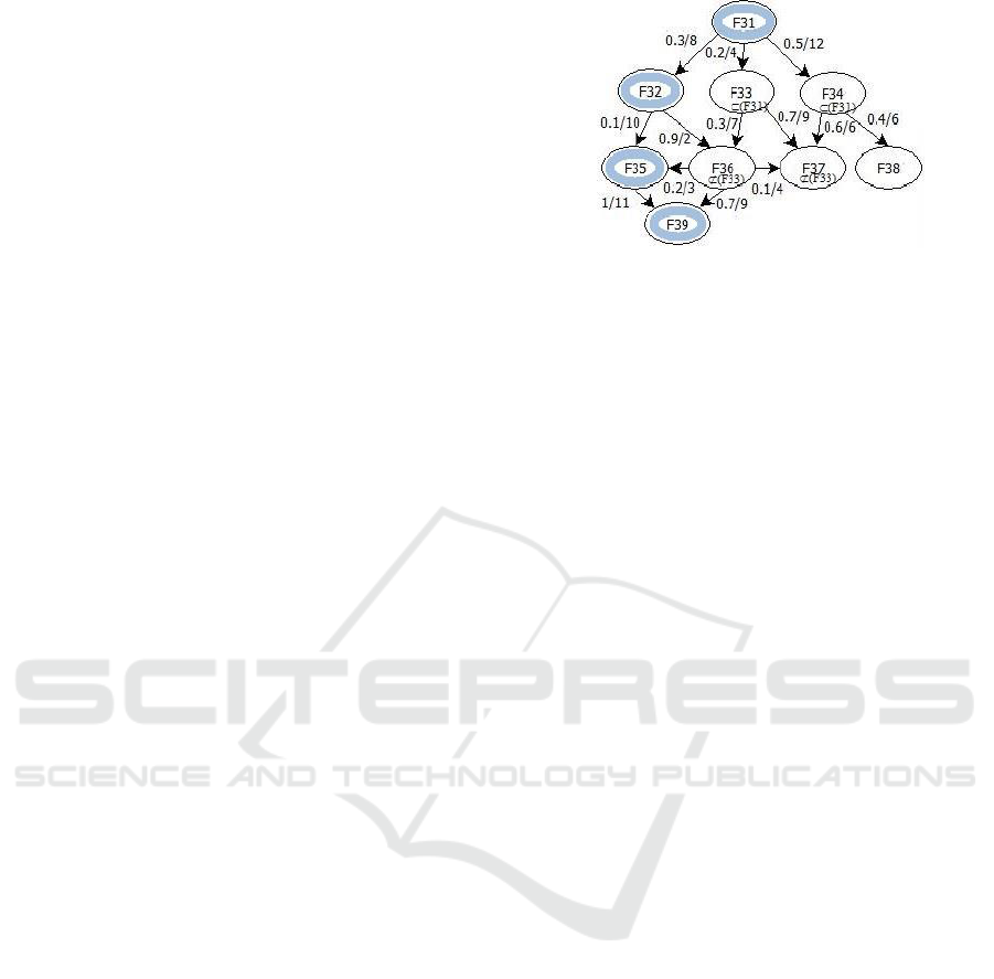
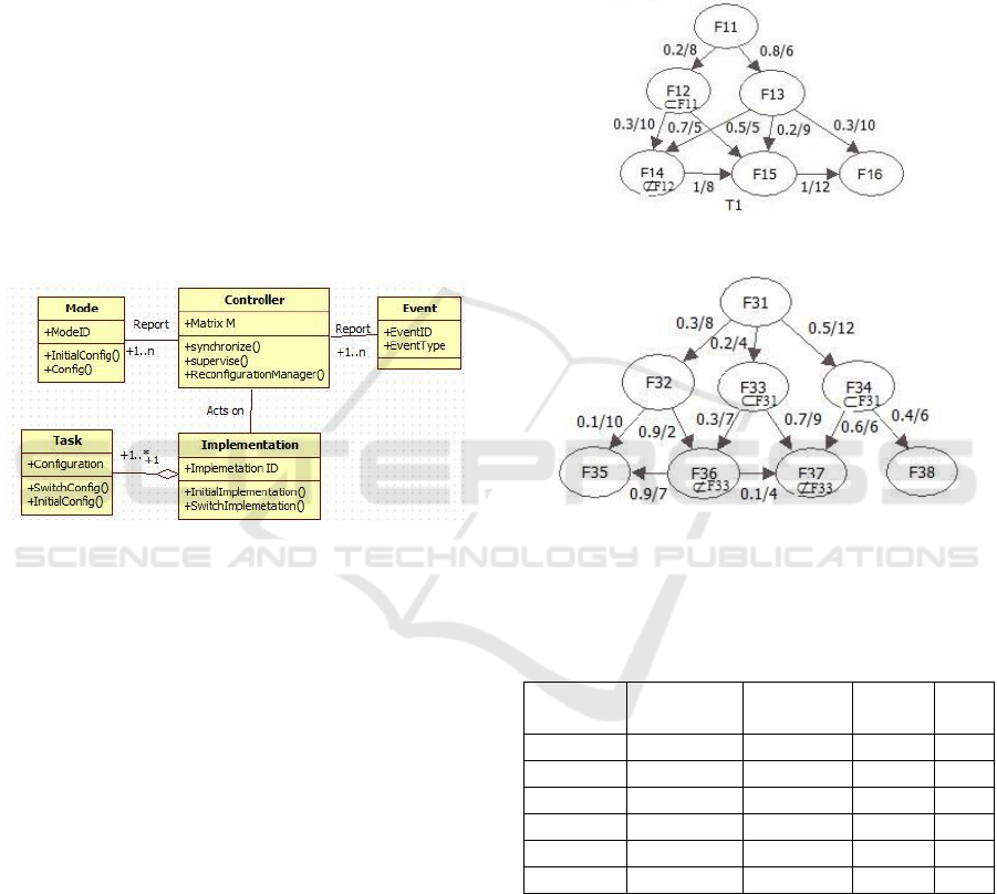
Fig.1 shows an example of a task T with
inclusion/exclusion, probability and communication
costs parameters. It represents an example of a
configuration and its path in the DAG of T.
Figure 1: Software task with a specified configuration path.
The software specification describes different
implementation scenarios. At each iteration an
implementation is designed to run on PEs. Each
implementation includes a certain number of software
tasks and it is defined as follows.
Definition 6 (Implementation).
An Implementation I is a set of tasks. It is formalized
by the simplet IID where: (i) IID: is the identifier of
the implementation.
Hence, we can define the system to be a set of
implementations, PEs and interconnects as follows.
Definition 7 (System).
A System Sys= {Implementation, PE, Interconnect}
A reconfiguration scenario can be related to the
current implementation of the system or to a
configuration path in one of the implementation tasks.
Hence, during execution another implementation
could be loaded or another configuration path could
be initiated. We define a reconfiguration scenario R
as follows.
Definition 8 (reconfiguration R).
A reconfiguration R is a triplet (RID, event, target)
where: (i) RID: The identifier of the reconfiguration
R, (ii) event: The event that induces R, (iii) target:
Specifies which implementation/configuration is
concerned with the reconfiguration.
3.2 Problem Statement
We consider the partitioning of a task set composed
of n tasks {T1,...,Tn} on a set of m PEs {PE1,...,PEm}.
The aim of our methodology is the following:
(1) Respect the inclusion/exclusion constraints
Fk, Fh
Assign-P(Pi) , Fk
Exclu (Fh).
Fk, Fh / Fk
Inclu(Fh) then Fk and Fh
Assign-P(Pi).
ICSOFT-EA 2016 - 11th International Conference on Software Engineering and Applications
356
(2) Respect the energy and the memory constraints
Fi
Assign-P(PEi),
Fi
Si
Weightmax.
Fi
Assign-P(PEi), EPEi
BL.
(3) Respect real-time constraints:
The utilization of a function Fi is ui = ci/pi. U
i
tot
is the total utilization of the k function on a
processor PEi , that is, U
i
tot
=
k
1
ci/pi
1.
The communication delays resulting of a
function Fk on PEi communicating with a
function Fh placed on PEj must not result in
functions missing their deadlines.
(4) Evaluate the impact of the design constraints on
the communication costs, the energy consumption
and the number of pre-emption.
4 I-CODESIGN METHODOLOGY
The goal of the I-codesign methodology is to achieve
a concurrent design between the probabilistic
software model and the hardware architecture in a
manner that fulfils all the system requirements and
respect the design constraints. I-codesign is a set of
models and transformations between models. All the
models are written in a system-level design language.
The transformations are a series of well-defined steps
through which the initial specification is gradually
mapped into a detailed implementation description.
After each design step, resulting models are analysed
to evaluate design metrics such as energy inclusion/
exclusion and communication costs. The main aim of
our co-design methodology is to map software
functions while respecting spatial and temporal
constraints for each implementation/configuration of
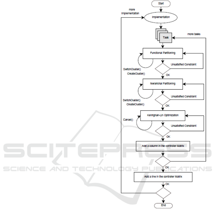
the system. Fig.2 shows the flow diagram of I-
Codesign methodology.
4.1 Hw/Sw Partitioning
We define the partitioning problem in a manner that
satisfies software constraints (spatial and temporal
constraints). At each phase of the partitioning, we
apply the appropriate rules first. Second, we verify
the memory and energy constraints jointly. When
validated, the feasibility analysis is applied.
Figure 2: I-Codesign state diagram.
4.1.1 Real-time Functional Partitioning
Evaluates the inclusion/exclusion constraints
between task functions and creates clusters depending
on this constraint. Couples that are concerned with
inclusion or exclusion constraints are placed in either
the same or different clusters. Once all the inclusions
and exclusions are evaluated, a feasibility analysis is
performed. If all clustered functions sets on the
created clusters are schedulable on one of the
available processors then the schedulability test is
validated. Otherwise, the functional partitioning is
applied again to create new clusters with schedulable
function sets. Since any inclusion/exclusion
New Co-design Methodology for Real-time Embedded Systems
357

constraint is hard, the clustered tasks are locked and
cannot be moved any more. The pseudo-code below
describes this partitioning phase.
Procedure Functional Partitioning {}
For each Function F of T
ExtractInclusion/Exclusion (F)
if (inclusion detected)
Cluster F with its predecessor
Else if (exclusion detected)
do not cluster F with its predecessor
End If
Lock (F)
lock (F’s predecessor)
End For
Generate Functional Graph
End Procedure
4.1.2 Real-time Hierarchical Partitioning
Clusters the remaining functions that have no
inclusion/exclusion constraints. The functions are
evaluated by their connecting edge’s probabilities and
high probability values are treated first. The available
memory space is evaluated at each iteration. Once all
the remaining functions are placed into clusters a
feasibility analysis is performed. If all the functions
sets on the created clusters are schedulable on one of
the available processors then the schedulability test is
validated. Otherwise, the hierarchical clustering is
applied again to generate clusters with schedulable
function sets. The pseudo-code below describes this
partitioning phase.
Procedure Hierarchical-partition{}
For each Function F non clustered
ExtractHighestEdgeProbability(F)
Choose the Edge with the Highest
Probability
Cluster (F, Function Connected To
Chosen Edge)
End For
Generate Initial Clusters
End Procedure
4.1.3 Real-time Kernighan-Lin
Optimizes the generated clusters. This phase
evaluates both probability and communication cost
on the edges connecting functions by gain
calculation. If the gain is positive, then the function is
moved to another cluster if its energy consumption on
the other cluster is less or equal to its energy
consumption on the original cluster. Otherwise it is
left on the original cluster. The pseudo code of the
kernighan-lin optimization is described below.
Procedure Kernighan-Lin{}
Choose an Unlocked Function F In
Partition1
calculate The Gain G(Partition1,
Partition2)
\If {$G \geq 0 $}
Move F to Partition2
End if
Generate Optimized Clusters
End Procedure
4.1.4 Feasibility Analysis
The feasibility test at each partitioning phase verifies
feasibility on the processors and on communication
links: (i) it verifies first whether the created clusters
are schedulable. Since we are using EDF algorithm
the feasibility test verifies on each PE
{PE1,...,PEm} the following inequation: U = ∑ci/pi
1 where ci is the execution time, pi is the period and
N is the number of functions placed on PEi. (ii) The
second test on the communication links verifies
whether or not the communications delays between
related functions affected to different PEs results in
functions missing their deadlines.
4.2 Multiprocessor Scheduling with
Precedence Constraint
The software specification is a set of independent
tasks modeled with a directed acyclic graph where
edges are functions and vertices are data
dependencies. Hence, a function is ready to execute
when all its predecessors are complete. We consider
the scheduling of a set of functions with simultaneous
release times, constrained deadlines and simple
precedence. The policy proposed below is derived
from (Forget et al., 2010). A set of simple precedence
is formalized by a relation →. Fi → Fj states that Fi
must execute before Fj. For a precise explanation of
the precedence problem the following assumptions
are considered:
Pred(Fi)= { Fj | (Fj → Fi) }
succ(Fi)= { Fj | (Fi,Fj)
→ g
The precedence constraint of the set of functions can
be encoded as follows where d
*
i
is the adjusted
deadline of a function Fi:
d
*
i
= min(di; min
Fj
succ(Fi)
( d
*
i-
cj)) (1)
Theorem 1. Let ₰= {Fi} a set of independent
functions and →
₰× ₰. Let ₰
*
= { F
*
i
} be a set of
independent functions such that d
*
i
is given by the
formula (1). We have₰ feasible if only ₰
*
is feasible.
ICSOFT-EA 2016 - 11th International Conference on Software Engineering and Applications
358
The scheduling algorithm uses the adjusted
parameters to perform the assignment of system
applications to the software or hardware domain.
Hence, the scheduling policy resides in adjusting the
function deadlines according to the equation (1).
4.3 Controller Generation
A reconfiguration can be specified for a software
implementation/configuration. We propose a
controller that involves: (i) observation mechanisms
of the system characteristics (energy, quality of
service ..) (ii) reconfiguration mechanisms that acts
on software tasks. The controller acts following
internal or external events that induce configurations.
A reconfiguration can add/remove implementation or
change the configuration path of a task that belongs
to the current implementation. Fig.3 shows the class
diagram of the controller.
Figure 3: Class diagram of the controller.
The controller class supervises the system
environment. It receives internal or external events
like user requests or peripheral entries and initiates
necessary reconfiguration. In fact, the controller is
responsible for loading the initial configuration of the
system, switching modes by moving from one
implementation to another and modifying the task’s
paths using the reconfiguration manager. A
configuration matrix is defined in order to associate
each implementation mode with its mapping on the
hardware units. The columns of the matrix are tasks
and associating functions, matrix lines are the
different system implementations. The intersection
between lines and columns defines a target processor
ID. For each implementation/configuration of the
system, we create an entry in the controller matrix
after applying the I-codesign methodology.
5 CASE STUDY
We propose in this section to apply the I-codesign
methodology to a software specification composed of
three implementations: S
1
= {T
1
, T
3
}, S
2
= {T
1
, T
3
,
T
4
} S
3
= {T
2
, T
3
, T
4
}.
Motivational Example: We propose to apply the
Icodesign techniques to S1. It is composed of two
independent tasks T
1
= {F
11
, F
12
, F
13
, F
14
, F
15
, F
16
} and
T
3
= {F
31
, F
32
, F
33
, F
34
, F
35
, F
36
, F
37
, F
38
}. T1 and T3
are represented respectively in Fig.4 and Fig.5.
Figure 4: Software task T1.
Figure 5: Software task T3.
The scheduling properties of the tasks T1 and T3 are
listed respectively in Table 1 and Table 2.
Table 1: Scheduling parameters of T1.
Function
Execution
Time
Deadline
Period
Si
F
11
5
120
150
5
F
12
3
120
200
7
F
13
2
90
210
2
F
14
6
110
150
6
F
15
2
120
190
3
F
16
2
200
250
5
This software model will be affected to a hardware
architecture composed of three homogeneous
processors PE
1
, PE
2
and PE
3
. The hardware units have
the characteristics shown in table 3. Each PE is
running with its highest frequency f, voltage V and its
memory size Si. We present in this section the results
of I-codesign on S
1
. The scheduling algorithm is EDF
(Earliest Deadline First).
New Co-design Methodology for Real-time Embedded Systems
359
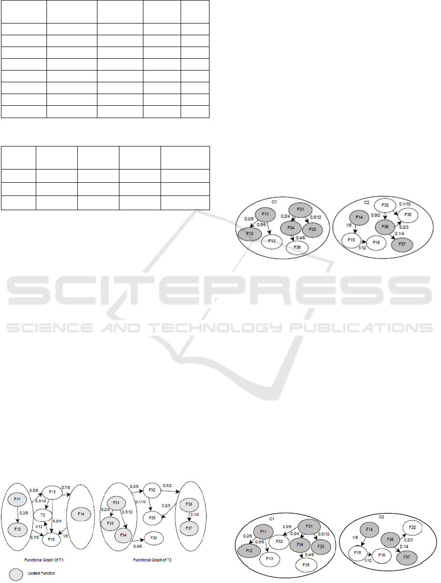
Table 2: Scheduling parameters of T3.
Function
Execution
time
Deadline
Period
Si
F
31
3
60
150
4
F
32
3
80
200
2
F
33
5
90
210
5
F
34
5
110
180
6
F
35
5
120
190
3
F
36
4
160
210
1
F
37
1
180
220
5
F
38
4
190
260
4
Table 3: Processor characteristics.
PE
F(Mhz)
V(V)
Weight
max
Battery
(watt)
PE
1
250/150
1.2/095
40
10
PE
2
300/200
1.3/1.08
40
10
PE
3
400/120
1.7/0.85
40
10
5.1 Functional Partitioning
The first step is to evaluate the inclusion/exclusion
constraints and generate initial clusters with locked
functions. These clusters will hold the functions
which respect the inclusion/exclusion constraints.
The functional partitioning creates two clusters. On
the first cluster C1, F
11
and F
12
of T
1
are affected with
F
36
and F
37
of T
3
. F
14
, F
31
, F
33
and F
34
are affected to
the second cluster C2. The functional graph is
constructed for each task. Fig.6 represents the
functional graphs of T
1
and T
3
respectively. We affect
C1to PE
1
’s parameters value and C2 to PE
2
’s
parameters value. Then, we verify the energy and
memory constrains first then we check the real-time
constraints. The consumed energy on PE
1
is E=1.44
10 and the consumed memory space is Mem=2740
on PE1. On PE2, E=4_10 and Mem=12
40. The
feasibility analysis is verified easily using the
CHEDDAR tool (Singhoff et al., 2004) for instance.
In order to verify that the communication delays do
not result in functions missing their deadlines we
Figure 6: Functional graph respectively of T
1
and T
3
.
create message dependencies between functions and
we affect each message with the communication cost
between the corresponding functions using
CHEDDAR tool. The Utilization Factor is U=0.12 on
PE1 and U=0.2 on PE2. Hence, the feasibility test is
valid.
5.2 Hierarchical Partitioning
The hierarchical clustering aims to generate initial
clusters by evaluating the probability as a metric. We
dispose of a functional graph generated by the
functional partitioning phase. We extract the highest
edge’s probability for each non clustered function F
j
and cluster it with its related clustered functions.
Hence, the link L
ij
between F
i
and F
j
communicates
only the less probabilistic traffic. The generated
clusters are shown in Fig.7.
Figure 7: Resulted clusters respectively of T1 and T3.
Then, energy and memory constraints are checked. The
used memory size Mem=35
40 and E=3.2
10 on PE
1
.
On PE
2
, Mem=23 and E=8.4
10. The real-time
constraints are verified. The Utilization Factor is U=0.18 on
PE1 and U=0.29 on PE2. Hence, the feasibility test is valid.
5.3 Kernighan-Lin Optimization
Kernighan-Lin optimizes the partitions based on
some metrics. In our partitioning process we use the
combination of two metrics: the probability on the
connecting edges and the communication cost. The
resulted clusters after applying the Kernighan-Lin
optimization are represented in Fig.8. After applying
the Kernighan-Lin algorithm, we notice that F
32
has
been moved from the cluster C2 to C1. The available
memory on PE
1
is 5 and the memory space of F
32
is
2, the new energy consumption on PE
1
is E=4.1. The
utilization is measured with cheddar tool minding the
Figure 8: Resulted clusters respectively of T
1
and T
3
.
ICSOFT-EA 2016 - 11th International Conference on Software Engineering and Applications
360
communication delays on the links: U =0.22. All the
I-codesign constraints are valid. Fig.8 shows the final
clusters C1 and C2 where C1 will be placed on PE
1
and C2 on PE
2
.
5.4 Scheduling Simulation Results
The scheduler receives the partitioning results as well
as the real-time characteristics of each function. Its
job is to determine which function executes on a
processor at a given time. We start with adjusting the
deadlines of the set of functions composing T1 and
T3. Table 5.6 and 5.7 present the adjusted values after
applying the precedence constraint formula (1).
Table 4: Adjusted scheduling parameters of T1.
Function
Execution
Time
Deadline
d
i
Period
d
i
*
F
11
5
120
150
88
F
12
3
120
200
104
F
13
2
90
210
90
F
14
6
110
180
110
F
15
2
120
190
120
F
16
2
190
250
190
Table 5: Adjusted scheduling parameters of T3.
Function
Execution
time
Deadline
di
Period
D
i
*
F
31
3
60
150
60
F
32
3
80
200
80
F
33
5
90
210
90
F
34
5
110
180
110
F
35
5
120
190
120
F
36
4
160
210
115
F
37
1
180
220
180
F
38
4
190
260
190
5.5 Controller Generation
The application controller use a matrix where each
line contains the functions of tasks and the columns
are the different system implementations. In this case,
we have three implementations S
1
, S
2
and S
3
. Table 6
shows the affectation of the task T1 in the controller
matrix for each implementation scenario.
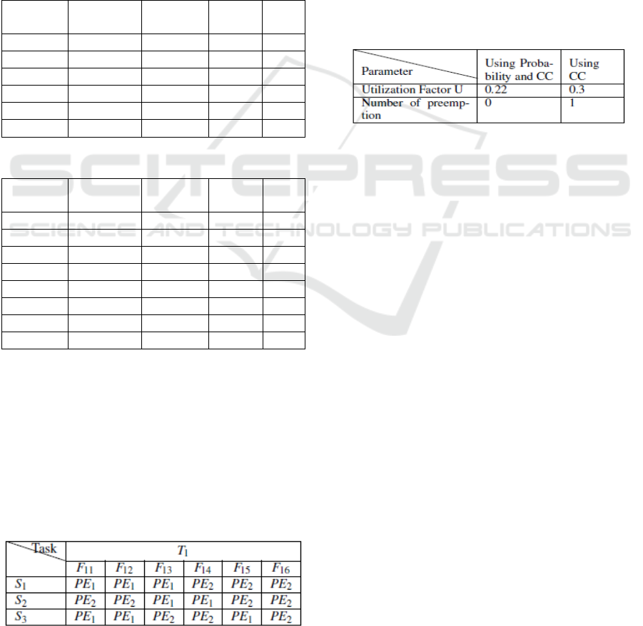
Table 6: Matrix entry for task T1.
5.6 Evaluation
In this section, we evaluate the impact of the
probabilistic aspect of the software tasks on the
schedulability factors. We eliminate the probability
on the edges and apply the partitioning based only on
the communication costs. We schedule then the
generated clusters. The tests are performed using
CHEDDAR environment. Table 7 presents a
comparison of some schedulability parameters
between the partitioning results using the probability
and the communication costs (CC) in one hand and
the communication costs only on the other hand. It is
clear that the probability enhances the schedulability
quality along with the optimization of the traffic
circulation.
Table 7: Comparison of the scheduling parameters with and
without probabilistic estimations.
6 SIMULATIONS
We have developed a tool environment to evaluate
the potential communication costs, energy savings
and execution costs for our methodology. The
following subsections describe our tool and the
assumptions made in its design. We show later some
simulations results.
6.1 Simulation Methodology
Using Java we developed a tool environment that
allows the partitioning and scheduling of the defined
software specification under energy, memory and
real-time constraints. The tool takes as an input
several sets of tasks characterized by different
parameters such as the probability estimations, the
communication costs and the exclusion/inclusion
between functions. The output is the controller
matrix. The parameters supplied to the simulator
include real time parameters for the functions at each
invocation. The simulation assumes that a constant
amount of energy is required for each cycle of
operation at a given voltage on a processor. The
hardware units are characterized with their memory
size, their battery charge, a list of frequencies and
voltage available and the throughput of
communication links that connects PEs.
New Co-design Methodology for Real-time Embedded Systems
361
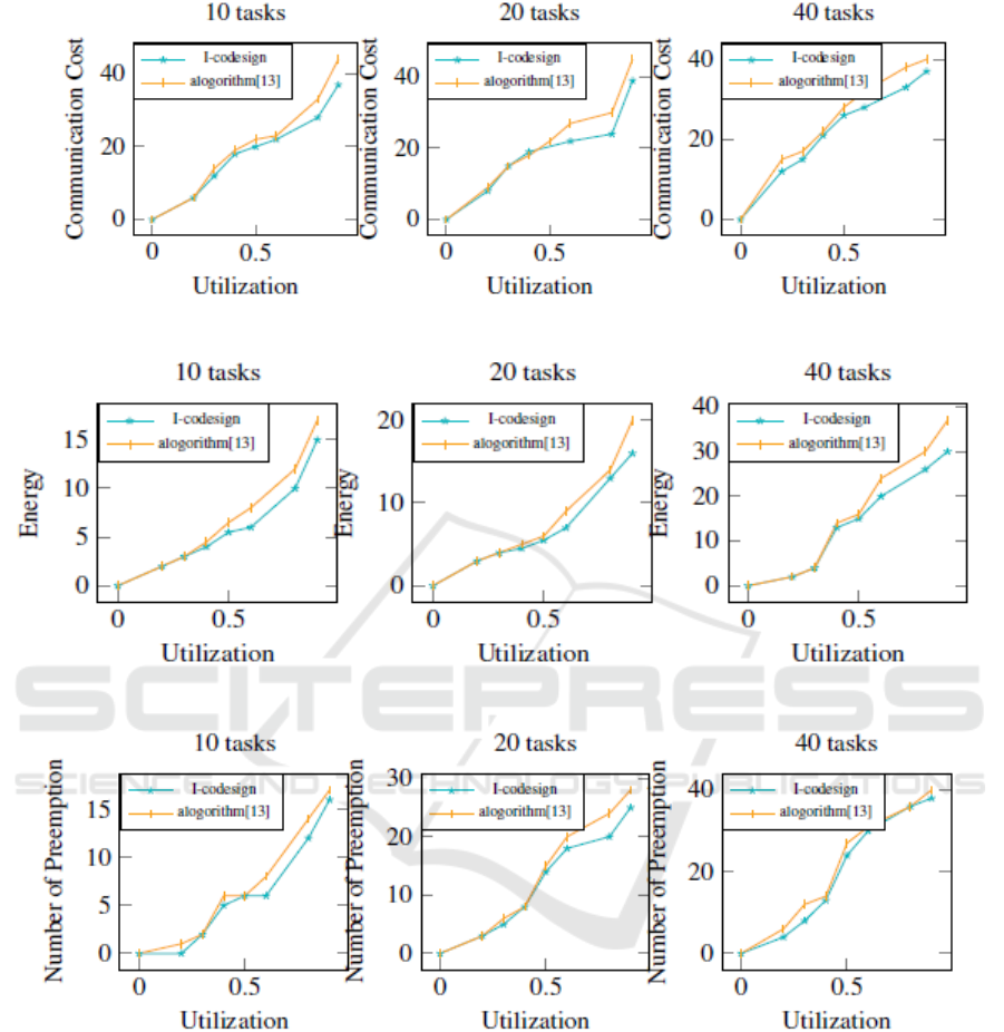
Figure 9: Communication costs with 10, 20 and 40 tasks.
Figure 10: Energy consumption with 10, 20, and 40 tasks.
Figure 11: Number of preemption with 10, 20 and 40 tasks.
6.2 Simulation Results
We have performed several simulations of the
Icodesign methodology to determine the system
parameters that affect the communication costs, the
energy consumption and the number of preemption.
In the following simulations, we compare the
proposed work with the partitioning and scheduling
approaches in (Shi et al., 2012). We determine the
effects of varying the number of tasks on the
communication costs of the communicating
functions placed on different PEs. Fig.9 shows the
communication costs for task sets with 10, 20 and
40 tasks while Fig.10 shows the energy
consumption on the same task set. Fig.11 presents
the number of preemption with both algorithms
using the same task set. We notice that the I-
codesign shows a good results for communications
costs, energy savings and preemption values
especially with high-range processor utilization
values.
ICSOFT-EA 2016 - 11th International Conference on Software Engineering and Applications
362

7 CONCLUSION
In this paper, a new co-design methodology is
introduced. The main contributions are adding
realtime memory and energy constraints to the
design process and generating a controller matrix
that maintains the defined systems characteristics
and constraints when executed. We have explored
the problem of task assignment with an objective to
respect inclusion/exclusion constraints, satisfy real-
time and memory constraints jointly and respect the
available amount of energy on the PEs. We carried
our experiments with the Earliest Deadline First
scheduling algorithm. Through the case study and
the simulation results, the probabilistic modeling is
proved to be efficient on communication cost,
energy consumption and number of pre-emption.
The traffic on the interconnection network is proved
to be reduced due to the probabilistic estimations of
the software tasks. However, the final
implementation of the tool environment needs
further improvements in mainly two aspects: first,
the development of a simulation framework for the
entire system and second, build a communication
interface to allow the hardware and the software
sides to interact.
REFERENCES
Banerjee, A., Mondal, A., Sarkar, A., and Biswas, S.
(2015). Real-time embedded systems analysis; From
theory to practice. Proceedings of VLSI Design and
Test (VDAT), 2015 19th International Symposium on,
Ahmedabad.
Banerjee, S., Bozorgzadeh, E., and Dutt, N. (2005).
Physically-aware HW-SW partitioning for
econfigurablearchitectures with partial dynamic
reconfiguration. Proceedings of 42nd Design
Automation Conference, 2005.
Cheng, O., Abdulla, W., and Salcic, Z. (2011). Hardware
Software Codesign of Automatic Speech Recognition
System for Embedded Real-Time Applications. IEEE
Transactions on Industrial Electronics.
C. M. Fiduccia and R. M. Mattheyes (1982). A Linear
Time Heuristic for Improving Network Partitions.
Proceedings of Design Automation, 1982. 19th
Conference on.
Ernst, R., Henkel, J., Benner, T., and Holtmann, U.
(1996). The COSYMA environment for
hardware/software cosynthesis of small embedded
systems. Proceddings of Microprocessors and
Microsystems.
Forget, J., Boniol, F., Grolleau, E., Lesens, D., and
Pagetti, C. (2010). Scheduling Dependent Periodic
Tasks without Synchronization Mechanisms.
Proceedings of Real-Time and Embedded Technology
and applicationsSymposium (RTAS), 2010 16th IEEE.
I. Ghribi, Abdallah, R., M. Khalgui, and M. Platzner
(2015). New Codesign solutions for modeling and
partitioning probabilistic reconfigurable embedded
software. Proceddings of ESM 2015, United
Kingdom.
Janakiraman, N. and Kumar., P. N. (2014). Multi-
objective module partitioning design for dynamic and
partial reconfigurable system-on-chip using genetic
algorithm. Journal of Systems Architecture.
Joshi, P. V. and Gurumurthy, K. S. (2014). Analysing and
improving the performance of software code for Real
Time Embedded systems. Proceedings of Devices,
Circuits and Systems (ICDCS), 2014 2nd
International Conference on, Combiatore.
Liu, P., Wu, J., and Wang, Y. (2012). Integrated Heuristic
for Hardware/Software Co-design on Reconfigurable
Devices. Proceedings of Parallel and Distributed
Computing, Applications and Technologies, 2012
13th International Conference on, Beijing.
Nikolic, B., Awan, M. A., and Petters, S. M. (2011).
SPARTS: Simulator for Power Aware and Real-Time
Systems. Proceedings of IEEE 10th International
Conference on Trust, Security and Privacy in
Computing and communications, Changsha.
Pillai, P. and Shin, K. G. (2001). Real-time dynamic
voltage scaling for low-power embedded operating
systems. In Proceedings of the Eighteenth ACM
Symposium on Operating Systems Principles, NY,
USA.
Poornima, B. and Kumar, V. (2008). A multilevel
partitioning approach for efficient tasks allocation in
heterogeneous distributed systems. Journal of
SystemsArchitecture.
P. Pillai and S. G. Kang (2001). Real-time Dynamic
Voltage Scaling for Low-power Embedded Operating
Systems. Proceedings of the Eighteenth ACM
Symposium on Operating Systems Principles, USA.
R. Camposano and Wilberg (1996). Embedded system
design. Proceedings of Design Automation for
Embedded Systems.
Shi, R., Yin, S., Yin, C., Liu, L., and Wei, S. (2012).
Energy-aware task partitioning and scheduling
algorithm for reconfigurable processor. Proceedings
of Solid-State and Integrated Circuit Technology,
IEEE 11th International Conference on, Xi’an.
Singhoff, F., Legrand, J., Nana, L., and Marce, L. (2004).
Cheddar: A Flexible Real Time Scheduling
Framework. Proceedings of the 2004 Annual ACM
SIGAda International Conference on Ada: The
Engineering of Correct and Reliable Software for
Real-time Distributed Systems Using Ada and Related
Technologies, USA.
Tang, J. W., Hau, Y. W., and Marsono, M. (2015).
Hardware software partitioning of embedded System-
on-Chip applications. Proceedings of Very Large
Scale Integration, 2015 IFIP/IEEE International
Conference on, Daejeon.
New Co-design Methodology for Real-time Embedded Systems
363

Teich, J. (2012). Hardware Software Codesign: The Past,
the Present, and Predicting the Future. Proceedings of
the IEEE.
Vahid, F. and Gajski, D. D. (1995). Incremental hardware
estimation during hardware/software functional
partitioning. Proceedings of IEEE Transactions on
Very Large Scale Integration Systems.
Wainer, G. (2013). Applying modelling and simulation
for development embedded systems. Proceedings of
2013 2nd Mediterranean Conference on Embedded
Computing (MECO).
Wang, X. W., Chen, W. N., Wang, Y., and Peng, C. L.
(2009). A Co-design Flow for Reconfigurable
Embedded Computing System with RTOS Support.
Proceedingsof Embedded Software and Systems,
2009. ICESS ’09. International Conference on,
Zhejiang.
ICSOFT-EA 2016 - 11th International Conference on Software Engineering and Applications
364
