
A Multi Finger Haptic Hand with Force Feedback
Mina R. Ramzy
1
, Emam F. Mohamed
2
, H. E. A. Ibrahim
2
and Yehia H. Hossamel-deen
3
1
Mechatronics Department, Higher Technological Institute, Tenth of Ramadan, Egypt
2
Electrical and Control Engineering Dept., Arab Academy for Science, Technology and Maritime Transport, Cairo, Egypt
3
Mechatronics Department, Future University in Egypt, Cairo, Egypt
Keywords: Robotic Hand, Glove Control, Haptic, Force Feedback.
Abstract: This paper presents a proposal for a twelve degrees of freedom robotic hand system controlled via haptic
technology with force control and force feedback. This robotic hand can be used in hazardous environment,
deserted places, or aerospace. To achieve this goal, an experimental set up in addition to a computer simulation
of this robotic hand system have been carefully designed and built. The experimental set up consists of three
main modules which are: the control Glove, the robotic hand, and a microcontroller. An integral controller
algorithm is applied to make the robotic hand track and follow the position and movement of the haptic glove
with force feedback. Three modes for force limitation are considered according to the application, which are
suitable for grasping of: brittle, elastic, and hard components. For computer simulation of the system, a
mathematical model has been derived considering a 3 DOF for each finger. To be compatible with robot hand
used in the experimental work, only four fingers are considered i.e. total 12 DOF. The experimental work
shows good gripping abilities following the glove movement and acceptable force feedback to the user hand,
while the simulation results give a qualitative agreement with the experimental ones.
1 INTRODUCTION
The word haptics is derived from the Greek word
haptikos that means “to be able to come into contact
with”. The study of haptics came from advances in
virtual reality. It is a form of human and computer
interaction that provides an environment that one can
explore through direct interaction with their senses.
For this project we are using a user at one end
(master) and a robot on the other (slave).
There must be feedback to interact with the
environment. That feedback is called haptic feedback
and also known as force feedback. As regards some
robotic tasks, a higher degree of precision is required,
which cannot be obtained from visual feedback only.
This adds a new dimension of control to help make
tasks more realistic. For example, the user should be
capable to feel the response from an object that she/he
touches at one end. Only the user at the control side
who can feel the response.
Haptics includes both kinesthetic and force
information that make the users to be able to feel the
texture of surfaces, temperature and vibration, etc.
and cutaneous (tactile) information that the skin feels
and do not necessarily need movement but rely
mainly on the skin receptors like the feel of forces
pushing on their skin and respond to them. The
feedback must be both accurate and fast enough to
meet the system requirements specified according to
the type of tasks that will be performed. (Adrian et al.,
2004).
A haptic system consists of two main parts: the
human part and the machine part. Both parts will be
provided with the necessary sensors, processors and
actuators. In the case of the human system, nerve
receptors implement sensing, brain implement
processing and muscles implement actuation of the
motion performed by the hand while in the case of the
machine part, the functions mentioned are performed
by the sensors, computer and motors; respectively.
(Rangoonwala et al., 2011).
The main objectives of this paper is to design and
implement a four finger robotic hand for grasping
objects of different shapes, sizes and material. This
hand is to be controlled by a glove. It follows the
movement of the user hand wearing the glove and at
the same time it gives the user a feel of how hard the
robotic hand is gripping the object by the force
feedback mechanism fixed to the glove. This project
has a variety of applications in the places where the
178
Ramzy, M., Mohamed, E., Ibrahim, H. and Hossamel-deen, Y.
A Multi Finger Haptic Hand with Force Feedback.
DOI: 10.5220/0005959401780184
In Proceedings of the 13th Inter national Conference on Informatics in Control, Automation and Robotics (ICINCO 2016) - Volume 2, pages 178-184
ISBN: 978-989-758-198-4
Copyright
c
2016 by SCITEPRESS – Science and Technology Publications, Lda. All rights reserved
user need to use his hands and at the same time to be
away of that place like hazardous environment,
deserted places, and aerospace.
2 MODELING
AND SIMULATION
The under actuation approach is use. In this approach
the number of actuators are less than the number of
DOF. The mechanical design determines the
movement and behavior of the passive finger joints.
One of the advantage of this approach is that the
finger adapt passively to the shape of the object being
grasped.
2.1 Dynamic Model of Finger
Mechanism
A phalanx is the section of the finger between each
joint so each finger, other than the thumb, has three
phalanges. Phalanx 1 is the one closest to the palm.
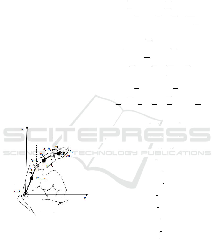
Figure 1 shows the forces, mass, and angles involved
in the movement of the phalanges of one finger only.
Figure 1: The spring loaded finger mechanism.
An idealized mechanical model is used in which
each phalange is assumed to be infinitely rigid with
its mass concentrated at the midpoint. All joints are
assumed frictionless. The first phalanx is assumed to
only move in a circular motion since the first joint is
assumed to be stationary and the phalanx is assumed
to be rigid. The motion of the masses m2 and m3 is
more complicated involving circular motion about the
joint and the movement of the joint. The Lagrangian
method is used to get the equations of motion. For
each finger, the three differential equations are
(Ramzy e.all, 2014):
(1)
(2)
(3)
Where
(4)
(5)
(6)
(7)
(8)
(9)
(10)
(11)
(12)
(13)
(14)
(15)
(16)
(17)
A Multi Finger Haptic Hand with Force Feedback
179
θi is the angle between the vertical and the ith
phalanx ,
Li is the length of the phalanx,
mi is the mass at the center of the ith phalanx,
ki is the spring stiffness coefficient of the spring of
ith joint, ci is the damping coefficient of ith joint
and
Ji is the moment of inertia of the ith phalanx.
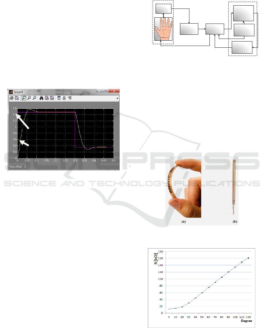
2.2 Simulation
A step input is applied to the SIMULINK model and
the finger response is plotted as shown in Figure 2.
Two step inputs are applied successively to record the
response in both direction of the finger movement.
The overall finger bend angle is plotted against time.
Figure 2: Simulated finger response (theta in radian).
3 EXPERIMENTAL WORK
The experimental process layout is shown in Figure1.
It is divided into three parts. The first part is the glove
that is divided into two parts: the flex sensor and the
feedback mechanism. The second part is the signal
processing and controller. The third part is the robotic
hand which contains the potentiometers for angle
feedback and the force sensor for the force feedback.
Several designs are made for both the robotic hand
and the feedback mechanism with the help of 3D
printer until we found the best performance of
grasping and following the commands of the human
hand. In the following subsections, each part will
briefly highlighted.
3.1 Glove
The glove contains two parts: The first part is the flex
sensor that converts the fingers movement to signals
Proportional to the angular movement of the fingers
for the controller. This represents the reference signal.
The second part is the force feedback mechanism.
Flex
sensor
Signal
processing
Robotic
hand
(mechanical
Controller
Force
sensor
Glove
Robotic hand
Pot.
Angle
measure
Figure 3: The process layout of the experimental setup.
3.1.1 Flex Sensor
The Flex Sensor is a resistive carbon elements
technology. As it is a variable printed resistor, The
Flex Sensor fulfills great form-factor on a thin
flexible substrate. Whilst it is bent see (Figure 4), the
sensor changes the resistance output value according
to the bend radius, the more it bends, the higher the
resistance value. Figure5 presents the characteristic of
flex sensor. This characteristic is obtained by the
datasheet of the used flex sensor. (spectrasymbol
manual).
Figure 4: Flex sensor (a) Flex sensor under bending (b) Flex
sensor in normal position.
Figure 5: The characteristic of flex sensor.
Input
response
ICINCO 2016 - 13th International Conference on Informatics in Control, Automation and Robotics
180
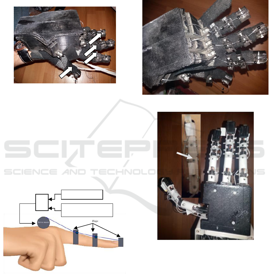
The main function of the flex sensor in the experiment
is to convert the human finger joints (knuckles) angle
movements to a proportional analogue signal. Figure 6
demonstrates the flex sensor setup on the hand. The
glove is used to fix the flex inside the fingers and the
force feedback mechanism.
Figure 6: The actual flex sensor setup on the hand and the
force feedback mechanism.
3.1.2 Force Feedback Mechanism
The force feedback mechanism is actuated by a servo
motor connected to the fingertip by a wire fixed to the
plastic rings fixed on the glove fingers. The wire runs
along the finger length across the rings. The servo
rotate according to the amount of the force applied to
the force sensor fixed to the tip of the robotic hand.
That gives the user the sense of how hard the robotic
hand is gripping the object. Figure 7 shows the glove
feedback mechanism diagram. Figure 8 shows the
actual glove feedback mechanism.
Figure 7: The glove feedback mechanism diagram.
3.2 Robotic Hand
The robot hand which is used in the experimental
work has twelve degrees of freedom.
Each finger has three degrees of freedom. It is
under actuated since one actuator moves the three
phalanges of each finger. This robotic hand will
mimic human hand. It adapts passively to the object
profile. Each finger is controlled by geared servo
motor to bend and elastic element to straighten.
Figure 9 shows robotic hand.
Figure 8: The actual glove feedback mechanism.
Figure 9: The robotic hand.
3.1.3 Force Sensing Resistor
Force Sensing Resistors (FSR) is a very thin, robust,
polymer device that when pressure is increased on the
surface of the sensor the resistance decreases. It is
used for the sensation of pressure, weight, contacts
and as a touch sensor. This FSR resistance will vary
depending on how much force (100g to 10kg /0.981N
to 98.1N) is being applied to the sensing area.
Figure10 shows Force sensing resistor (FSR) while
Figure11 presents its characteristics. This
Equivalent to
Force sensor (robotic finger)
Flex sensor ( glove)
+
-
Elastic
element at
the back of
the finger
Flex
sensor
inside
the
glove
A Multi Finger Haptic Hand with Force Feedback
181
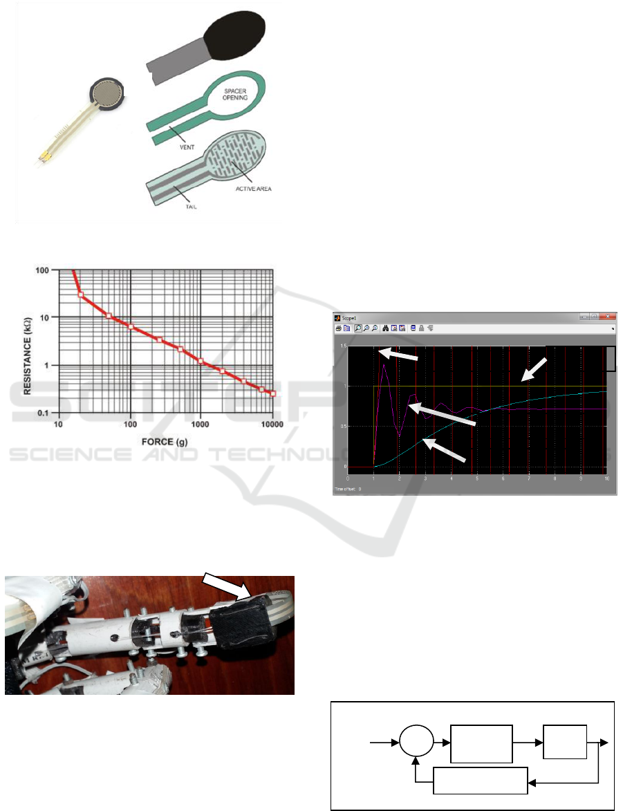
characteristic is obtained by the datasheet of the used
FSR (Interlink electronics catalog).
Figure 10: Force sensing resistor (FSR).
Figure 11: Characteristics of force sensor.
The main function of force sensor in the
experiment is to convert the force on the tip of the
robotic finger to an analogue signal. Figure 12
demonstrates the force sensor setup on the robotic
finger.
Figure 12: The actual force sensor setup on the robotic
finger.
In this work, three modes of force limitation are
to be considered according to the robotic hand
application. The first mode is for brittle objects like a
lamp (30N). The second mode is for elastic objects
like rubber ball (70N). The third mode is for hard
objects (98N). The 3 modes values are assumed for
demonstration and proof of the applicability of the
concept. Actual limiting value needs more search.
3.3 The Controller
The Arduino Mega is a microcontroller board uses the
ATmega1280. It is the Microcontroller which is used
in the experimental work. It is used to convert the
analogue signal from the flex sensors signal and force
sensor to a digital signal.(Arduino manual) According
to the integral control algorithm , it will send
commands to the servos to control the robotic hand
and the feedback mechanism. In our experimental
work, kp and kd unexpectedly leaded to instability.
Only the ki had normal effect on the system response.
The increase of Ki decreases the rise time but
increases the overshoot and vice versa. So we used
the fine tuned integral controller. Figure13
demonstrates the effect of ki on a simple system with
different ki values.
Figure 13: The effect of different ki on a simple system.
By applying the fine tuned integral controller, the
overshoot is minimized and at the same time the rise
time is kept small. In this fine tuned integral
algorithm, a higher Ki is used at first then a smaller
Ki near the required value. Ki was found
experimentally. The known tuning methods (e.g.
Ziegler-Nichols tuning method) were not applicable
to our system due to instability with any values for ki
and kd. Figure 14 shows the closed loop block
diagram of the finger.
Figure 14: The closed loop block diagram of the finger.
Flexible substrate with
printed semiconductor
Spacer adhesive
Flexible substrate with printed
interdigitating electrodes
Adaptive
Integral
controller
Finger bent angle
Robotic
hand
+
Ref
angle
-
Force sensor
Response without controller
Response with ki = 0.1
Response with ki = 10
Step input
ICINCO 2016 - 13th International Conference on Informatics in Control, Automation and Robotics
182
3.4 Experimental Results
A prototype version of this robotic hand has been
constructed and tested. The controlling algorithm
software has been written in C and uploaded to the
Arduino microcontroller.
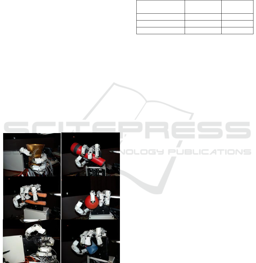
To test the grasping ability of the hand, it was made
to grasp different objects, each having different
shape, size, surface conditions and hardness, and the
force feedback by the user sense. The object was held
so that the center of mass was within the workspace
volume of the thumb and fingers and oriented to grasp
so that the major axis of the object was parallel to the
palm and aligned with the fingers. Once the objects
were positioned in the work space of robotic hand, the
user moves his hand that is wearing the glove in
grasping movement. The grasp was determined to be
successful if the robotic hand correctly held the object
and the user feels the hardness of the grasp by the
force feedback mechanism. Figure15 shows the robot
hand grasping different objects of different geometry.
The response of the robotic hand was monitored and
adjusted by the Integral controller algorithm. The
overall robotic finger bend angle is plotted against
time In Figure 16 (A)&(B) for the cases without and
with control; respectively. To be noted it is plotted by
MegunoLink plotting tool.
Figure 15: The robotic hand grasping a variety of objects
(Cup, torch, pliers, Ball, light Bulb, and bottle).
From figure 16, it can be seen that the improvement
in the response after applying the fine tuned integral
control. Table 1 shows the characteristics of the
system response with and without the controller.
Table 1: The characteristics of the system response with and
without the controller.
Without
controller
With
controller
Overshoot
5.5%
Negligible
Rise time
0.2667 s
0.24 s
Steady state error
Negligible
Negligible
4 CONCLUSIONS &
RECOMMENDATIONS
A proposal for a robotic hand system controlled via
haptic technology with force control and force
feedback is introduced. This robotic hand mimics the
movement of glove worn on a human hand. This
robotic hand can grasp a variety ofobjects with
different surface characteristics and shapes. It adapts
passively to the objects profile & material. Three
modes for force control can be selected by user which
makes the proposed system suitable to be used with
different objects with different brittleness or softness.
The force feedback mechanism gives the user sense
of the how hard the robotic hand gripping the object
Both the experimental and simulation results show a
qualitative agreement in response to a step reference
input. A fine tuned integral control system has been
utilized to enhance the performance of this system.
The application of this control algorithm improves the
overshoot from 5.5% to negligible and the rise time
from 0.2667s to 0.24S. The instability for all values
of Kp and Kd in the PID controller need more
investigation to be able to apply better control. This
proposed system can be used in hazardous
environment, deserted places, or aerospace.
However, this robotic hand has some limitations as it
cannot be used to perform fine manipulations like
writing. More future work can be done in this area.
Also, the control of which mode to be applied (Brittle,
elastic, or hard) is done through switches adjusted
manually. Future work is needed to be implemented
autonomously.
A Multi Finger Haptic Hand with Force Feedback
183
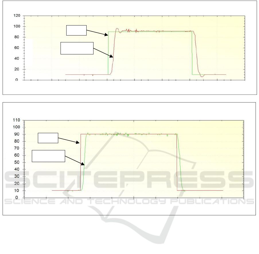
Figure 16: The experimental response of the robotic hand (A) Without control (B) With control.
REFERENCES
Adrian Cuadra, Colson Griffith, Scott Gunther, Krista
Hirasuna, Matt Kalkbrenner, Carol Reiley, C. (June 9,
2004). “Haptic Integration of an IBM Robotic
Manipulator.” Santa Clara University, Department of
Computer Engineering, Electrical Engineering, and
Mechanical Engineering.
Rangoonwala Denish, Mr.Nikunj Patel “A seminar report
on haptic technology” 2011, C. K. Pithawal college
of engineering & technology, Surat.
Fahad W. and Muhammad A., “Dynamic Finger
Movement Tracking and Voice Commands Based
Smart Wheelchair”, International Journal of
Computer and Electrical Engineering, Vol. 3, No. 4,
2011, pp. 497–502.
“FSR® Integration Guide & Evaluation Parts Catalog
with Suggested Electrical Interfaces”, Interlink
electronics, California.
Flex sensor special edition length, spectrasymbol, USA.7.
Klaus Schmidt, MSc. Johan Tegin, MSc. Pieter Grebner,
“Robot hand design -palm improvement and a robotic
hand-arm interface”, Royal institute of technology
(KTH).
Ramzy Mina, Haggag Salem, Hossamel-din Yehia ,
“Modeling and verification of spring loaded robotic
finger mechanism”, presented and published on:
“2014 15th International Workshop on Research and
Education in Mechatronics (REM), El Gouna, Red
Sea, Egypt, 9-11 september 2014- published on IEEE
explorer; http://ieeexplore.ieee.org/stamp/stamp.jsp?
tp=&arnumber=6920235&isnumber=6920214,
doi:101109/REM.2014.6920235.
https://www.arduino.cc/en/Main/ArduinoBoardMega.
Input
Response
0 1 2 3 4 5 6 7 8
Time (s)
(A)
0 1 2 3 4 5 6 7 8 9
10 Time (s)
Input
Response
Theta
(deg.)
(B)
ICINCO 2016 - 13th International Conference on Informatics in Control, Automation and Robotics
184
