
A Generation Method of Speed Pattern of Electric Vehicle
for Improving Passenger Ride Comfort
Hidetake Fuse
1
, Tohru Kawabe
2
and Masayuki Kawamoto
3
1
Chiyoda Corporation, Yokohama 220-8765, Japan
2
Division of Information Engineering, Faculty of Engineering, Information and Systems, University of Tsukuba,
Tsukuba 305-8573, Japan
3
International Innovation Interface Organization, University of Tsukuba, Tsukuba 305-8550, Japan
Keywords:
Ride Comfort, Speed Pattern, Optimal Control, Acceleration/Deceleration, Jerk.
Abstract:
This paper deals with the passenger ride comfort of electric vehicle. A generation method of speed pattern is
proposed for improving the ride comfort against the longitudinal acceleration/deceleration. The speed pattern
generated using proposed technique is based on the general optimal control theory with evaluating the accel-
eration and the jerk which is time derivative of the acceleration. The effectiveness of the present method is
demonstrated through numerical experiments.
1 INTRODUCTION
From the point of view of preventing a motion sick-
ness and an accident, the ride comfort of the car is
very important(Nozaki, 2008). Because vibration in-
fluences ride comfort, many studies are performed
about the relation of vibration and ride quality from
the past(Akatsu, 1998; Cucuz, 1994). An active sus-
pension control system (Itagaki et al., 2013) is a typi-
cal example.
However, these studies are mainly investigated on
ride comfort against the vibration in the vertical di-
rection, and there are few study on ride discomfort
due to longitudinal acceleration/deceleration or tun-
ing motion. As well as the vibration, it is important
to consider the influence on lateral speed change for
improving overall ride comfort.
Therefore, in this paper, we propose the genera-
tion method of longitudinal speed pattern using the
jerk which is time derivative of the acceleration and
the acceleration as the evaluation index, for improv-
ing the ride comfort against the longitudinal accelera-
tion/deceleration. The proposed method aims to con-
tribute to improvement of beginner driver’s driving
skill from the viewpoint of passenger’s comfortabil-
ity by showing the ideal running pattern and checking
the driving.
An electric vehicle (EV) is made the target in this
paper. Since EVs have several advantages, compared
with the internal-combustion engines (ICEs), as fol-
lows (Brown et al., 2010; Tseng et al., 2013).
1) The input/output response is faster than for gaso-
linediesel engines. It is said that the motor torque
response is 2 orders of magnitude faster than that
of the engine. E.g., if engine torque response costs
500 ms, the response time of motor toque will be
5 ms.
2) The torque generated in the wheels can be de-
tected relatively accurately. For engine, the out-
put torque varies along with the temperature and
revolutions, even it has high-nonlinearity. Conse-
quently the value of torque is too difficult to be
measured accurately. However, the value of mo-
tor torque is surveyed easily and accurately from
the view of current control.
3) The motor can be made small enough, then the ve-
hicles can be made smaller by using multiple mo-
tors placed closer to the wheels. The drive wheels
can be controlled fully and independently. E.g.,
it becomes easily achievable to control the differ-
ences of driving force developed between the left
and right wheel.
From these good points of EVs, we can realize the su-
perior running of vehicle with the good ride comfort
by using the proposed speed pattern. Also, it can be
applied some type of autonomous vehicle, for exam-
ple, PRT (Personal Rapid Transit) and so on.
The rest of this paper is organized as follows: Sec-
tion 2 states the evaluation of ride comfort. In Section
152
Fuse, H., Kawabe, T. and Kawamoto, M.
A Generation Method of Speed Pattern of Electric Vehicle for Improving Passenger Ride Comfort.
DOI: 10.5220/0005954901520157
In Proceedings of the 13th Inter national Conference on Informatics in Control, Automation and Robotics (ICINCO 2016) - Volume 2, pages 152-157
ISBN: 978-989-758-198-4
Copyright
c
2016 by SCITEPRESS – Science and Technology Publications, Lda. All rights reserved

3, the proposed generation method of speed pattern is
presented. The extended proposed method is shown
and simulation results are discussed in Section 4. Fi-
nally, we end the paper with some conclusions and
future work in Section 5.
2 EVALUATION OF RIDE
COMFORT
There are various factors which have an influence on
ride quality, but the index of the ride quality depends
on individuals. About the railroad carriage, various
research about the evaluation of the ride comfort with
respect to the frequency of vibrations in vertical and
horizontal directions have been reported (Nakagawa,
2010).
However, most of these deal with the evaluation
of ride comfort with respect to the sustained vibration
of the steady run or vibration in the vertical direction.
In the case of EVs, it is important to evaluate the ride
comfort with respect to lateral speed change. In re-
lation to this point, there are (Wang et al., 2000) and
(Wang et al., 2002) as the study which investigated
the relation between the acceleration/deceleration ,
the jerk (time derivative of the acceleration) and ride
quality. In (Wang et al., 2000; Wang et al., 2002),
subjectivity rating of the ride comfort tests about a
start, a stop, immediate start, a run including the hit-
ting the brakes for the resting posture and the reading
posture and derive the following linear multiple re-
gression model for the ride comfort index.
d(t) = β
0
+ β
1
a
p+
(t) + β
2
a
p−
(t)
+β
3
j
r+
(t) + β
4
j
r−
(t) + ε(t) (1)
where parameters in equation (1) are defined in table
1. And where a
p+
(t), a
p−
(t), j
r+
(t), j
r−
(t) in T =
(t − 3,t) are given as follows.
Table 1: Definition of parameters.
d(t) ride comfort index at time t
a
p+
(t) peak value of acceleration in T = (t − 3,t)
(3 seconds just before time t)
a
p−
(t) peak absolute value of deceleration in T
¯
j(T ) average value of jerk in T
j
r+
(t) effective value of jerk in the case of
positive value of
¯
j(T )
j
r−
(t) effective value of jerk in the case of
negative value of
¯
j(T )
ε(t) error term
β
0
constant term
β
k
Partial regression coefficient
a
p+
(t) =
(
max
t∈T
a(t), (|max
t∈T
a(t)| ≥ |min
t∈T
a(t)|)
0, (|max
t∈T
a(t)| < |min
t∈T
a(t)|)
(2)
a
p−
(t) =
(
0, (|max
t∈T
a(t)| ≥ |min
t∈T
a(t)|)
min
t∈T
a(t), (|max
t∈T
a(t)| < |min
t∈T
a(t)|)
(3)
j
r+
(t) =
(
q
1
3
R
t
t−3
j
2
(τ)dτ, (
¯
j(T ) ≥ 0)
0, (
¯
j(T ) < 0)
(4)
j
r−
(t) =
(
0, (
¯
j(T ) ≥ 0)
q
1
3
R
t
t−3
j
2
(τ)dτ, (
¯
j(T ) < 0)
(5)
Unfortunately, it is not possible to derive the speed
pattern by using d(t) directly since the d(t) is ride
comfort index at the specific time t derived based on
the acceleration and the jerk in the real time. It can’t
show overall evaluation.
Then we need to consider other index for gener-
ating the speed pattern for overall ride comfort. In
(Wang et al., 2000; Wang et al., 2002), we can see that
the value of deceleration, the value of jerk in deceler-
ation, the value of jerk in acceleration and the value
of acceleration have big influence on the ride quality
by their order. Therefore, it is important to suppress
both of the acceleration/deceleration and the jerk to
improve the ride quality and we can build the genera-
tion method of speed pattern based on these index.
3 GENERATION METHOD OF
SPEED PATTERN
The speed pattern is defined as the ideal speed plan to
satisfy various demands/limits for ride comfort, en-
ergy efficiency at acceleration, position, time and so
on. In (Zhao and Hori, 2006), the speed pattern is
derived based on the SMART control method (Mi-
zoshita et al., 2006) by using following evaluation
function.
J
0
=
Z
t
f
0
(
da
dt
)
2
dt (6)
where a is the acceleration and t
f
is the terminal time,
and where the state-space vehicle model is as
˙v
˙a
=
0 1
0 0
v
a
+
0
1
u (7)
However, the acceleration, which is one of the
most important factor influenced to the ride quality as
I mentioned in Sec. 2, does not include directly in this
evaluation function. In addition, a vehicle position is
A Generation Method of Speed Pattern of Electric Vehicle for Improving Passenger Ride Comfort
153
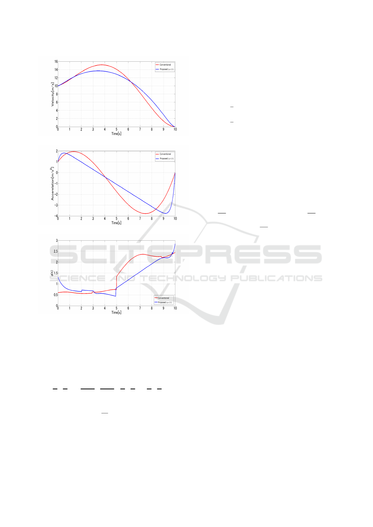
Figure 1: Time response of vehicle speed.
Figure 2: Time response of vehicle acceleration.
Figure 3: Time response of ride comfort index d(t).
not included in this model. It’s important factor for re-
alizing the automatic driving in the near future. From
these facts, the state space model and the evaluation
function in this paper is defined as follows.
˙x
˙v
˙a
| {z }
˙
x
=
0 1 0
0 0 1
0 0 0
| {z }
A
x
v
a
| {z }
x
+
0
0
1
| {z }
B
u (8)
J
1
=
Z
t
f
0
(
da
dt
)
2
+ q
2
a
2
dt (9)
It’s also possible to control the vehicle position to
add x in the state space variables for automatic driv-
ing. Furthermore, we can derive the the speed pattern
which emphasized the ride comfort against the accel-
eration and deceleration by adding the weighted a to
evaluation function. (q is the weighting constant.)
Then, by using the generalized optimal control
theory, we can derive the following Hamiltonian H
from equations (8) and (9).
H =
1
2
(u
2
+ a
2
) + λ
T
(Ax + Bu)
=
1
2
(u
2
+ x
T
Qx) + λ
T
(Ax + Bu)
(10)
where λ is the Lagrange multiplier and where
Q =
0 0 0
0 0 0
0 0 q
2
(11)
The solution minimized J
1
is obtained as
u = −B
T
λ (12)
Finally we can derive the following speed pattern af-
ter deformation of equations with state space equa-
tion: ˙x =
∂H
∂λ
, co-state space equation:
˙
λ = −
∂H
∂x
and
stationarity equation:
˙
0 =
∂H
∂u
.
x(t) = C
0
e
qt
+C
1
e
−qt
+C
2
t
3
+C
3
t
2
+C
4
t +C
5
v(t) = qC
0
e
qt
− qC
1
e
−qt
+ 3C
2
t
2
+ 2C
3
t +C
4
a(t) = q
2
C
0
e
qt
+ q
2
C
1
e
−qt
+ 6C
2
t + 2C
3
(13)
where C
j
( j = 0, 1,2,3,4, 5) are constant coefficients.
These values can be decided from initial and terminal
conditions for t, x, v and a.
This speed pattern include the method by (Zhao
and Hori, 2006).
One example of simulation result is shown to con-
firm this fact. Let’s consider the following initial and
terminal conditions.
t
0
= 0 : x
0
= 0, v
0
= 10, a
0
= 1
t
f
= 10 : x
f
= 100, v
f
= 0, a
f
= 0
(14)
These conditions show the situation that vehicle runs
from a state running in speed 10m/s and acceleration
1m/s
2
to the 100m spot ten seconds later, and to stop.
In figures 1 ∼ 3, red line indicates the result by
the conventional method ((Zhao and Hori, 2006)) and
blue line indicates the result by the proposed method
with q = 3.5 which minimized total sum of d(t).
Figures 1 and 2 show the time response of vehicle
speed and acceleration respectively. From these fig-
ures, we can see that both methods (the proposed and
the method in (Zhao and Hori, 2006)) can generate the
speed pattern satisfied initial and terminal conditions.
Figure 3 shows time response of d(t) . We can see
that the proposed method can suppress the value of
d(t) lower than the method in (Zhao and Hori, 2006)
ICINCO 2016 - 13th International Conference on Informatics in Control, Automation and Robotics
154
in the most part of the whole running period. There-
fore, we find out that the proposed method can im-
prove the ride comfort than the method in (Zhao and
Hori, 2006).
4 EXTENDED GENERATION
METHOD OF SPEED PATTERN
In this section, the proposed method given in Section
3 is extended to the flexible generation method which
can cope with the change of terminal conditions in
the way of the run for practical use. For example, the
method is extended to be able to deal with the situa-
tion that it is necessary to shorten a stop spot by some
kind of factors such as other vehicles getting into the
way. In such situation, the speed pattern should be re-
generated in real-time accordance with the change of
conditions.
4.1 Extended Method
As the result of many simulations, we see that the re-
maining run time after the pattern re-generated greatly
influenced the quality of ride comfort. Since the
change of the run time brings the sudden change of
the jerk. Therefore the following evaluation function
(J
2
) is introduced to decide appropriate remaining run
time.
J
2
= rx + sy (15)
where x is the absolute value of the difference of the
value of the jerk just before and after the pattern re-
generated, y is the absolute value of the difference of
the derivative value of the jerk just before and after
the pattern change, and r, s are constant weights. Be-
cause it was a problem that the jerk suddenly changes
in before and after the pattern re-generated, appropri-
ate values of the weight q of J
1
in equation (9) and
the remaining run time are decided by using this eval-
uation function (J
2
in equation (15) for the change of
jerk consecutively and smoothly as much as possible.
In addition, a search range at remaining run time
is set. For example, the search range is set as not ex-
ceeding the whole running time set beforehand. If the
running distance becomes long, remaining run time
is able to be increased and search the best values of
q and the remaining run time in the enlarged range.
Then, it becomes possible to derive the speed pattern
with best ride comfort, which minimize the total d(t)
in whole running time, against the change of terminal
conditions.
4.2 Numerical Examples
Let’s confirm the effectiveness of this extended
method in some simulations.
Firstly, let’s consider the situation that the stop
spot is shortened after starting off. The first condition
is as follows.
t
0
= 0 : x
0
= 0, v
0
= 0, a
0
= 0
t
f
= 10 : x
f
= 100, v
f
= 0, a
f
= 0
(16)
Then, at running 60m spot, the stop spot is shortened
from 100m to 70m as follows.
t
0
= 0 : x
0
= 60, 0 = v
s
,a
0
= a
s
t
f
= [search] : x
f
= 70, v
f
= 0, a
f
= 0
(17)
where v
s
is final speed value before re-generate the
speed pattern and a
s
is final acceleration value before
re-generate the pattern.
The results by the proposed extended method are
shown as figures 4 ∼ 6. In this simulation, the pattern
is re-generated at 5.61s, weights are q = 2.2,r = 1, s =
0 and remaining run time after regeneration of pattern
is 1.00s.
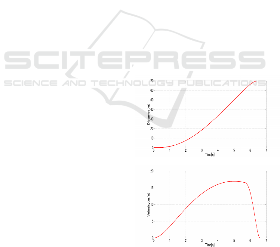
4.2.1 Simulation I
We can see that the method can cope with the sudden
change of stop spot from figures 4 and 5. From fig-
ure 6, the ride comfort becomes worse at the time of
Figure 4: Time response of vehicle position (Simulation I).
Figure 5: Time response of vehicle speed (Simulation I).
A Generation Method of Speed Pattern of Electric Vehicle for Improving Passenger Ride Comfort
155
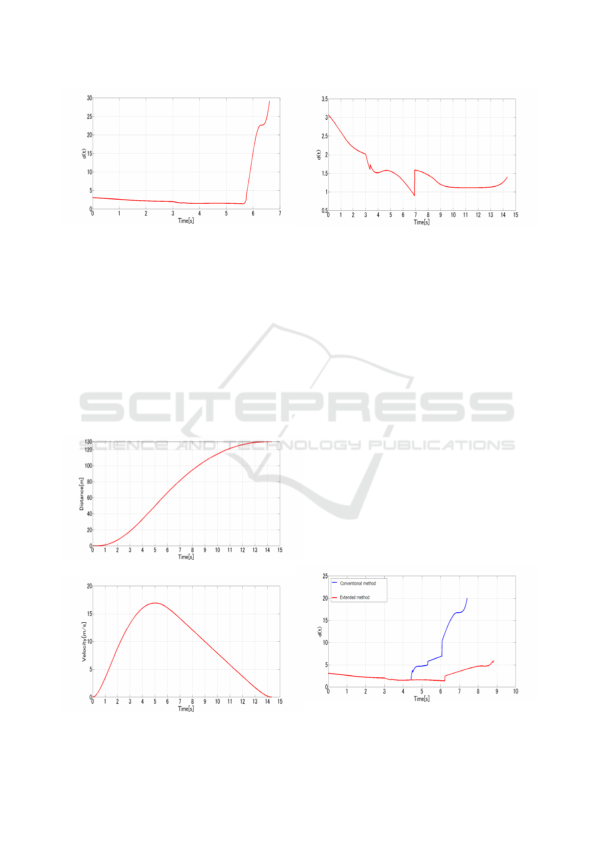
Figure 6: Time response of ride comfort index d(t) (Simu-
lation I).
shortening the stop spot (5.61s). But it’s natural re-
sponse due to the sudden shortening of stop distance
for safety.
4.2.2 Simulation II
Let’s consider the situation that the stop spot is length-
ened after starting off. The first conditions as follows.
t
0
= 0 : x
0
= 0, v
0
= 0, a
0
= 0
t
f
= 10 : x
f
= 100, v
f
= 0, a
f
= 0
(18)
Then, at running 60m spot, the stop spot is lengthened
from 100m to 130m as follows.
t
0
= 0 : x
0
= 60, 0 = v
s
,a
0
= a
s
t
f
= [search] : x
f
= 130, v
f
= 0, a
f
= 0
(19)
Figure 7: Time response of vehicle position (Simulation II).
Figure 8: Time response of vehicle speed (Simulation II).
Figure 9: Time response of ride comfort index d(t) (Simu-
lation II).
The results by the proposed extended method are
shown in figures 7 ∼ 9. In this simulation, the pattern
is re-generated at 5.61s, weights are q = 1.9,r = 1, s =
0 and remaining run time after pattern re-generated is
8.173s.
From these figures, we can see that the method can
cope with the situation of lengthening the stop spot.
From figure 9, the ride comfort index d(t) turns worse
suddenly at about 6.9s. This is because the absolute
value of the acceleration is bigger than the one before
3s, and it has a big influence on the d(t). But, after
6.9s the value of d(t) is suppressed gradually.
4.2.3 Simulation III
In this section, the proposed extended method is com-
pared with the conventional method ((Zhao and Hori,
2006)) in the situation that the stop spot is shortened
after starting off. The first condition is as follows.
t
0
= 0 : x
0
= 0, v
0
= 0, a
0
= 0
t
f
= 10 : x
f
= 100, v
f
= 0, a
f
= 0
(20)
Then, at running 40m spot, the stop spot is short-
ened from 100m to 90m as follows.
t
0
= 0 : x
0
= 40, 0 = v
s
,a
0
= a
s
t
f
= [search] : x
f
= 90, v
f
= 0, a
f
= 0
(21)
Figure 10: Time response of ride comfort index d(t) (Sim-
ulation III).
ICINCO 2016 - 13th International Conference on Informatics in Control, Automation and Robotics
156

The result of comfort index d(t) is shown as figure
10 . In this simulation, the conventional method got
worse the ride quality after situation changes. On the
other hand, the proposed extended method can cope
with the change.
5 CONCLUSIONS
In this paper, we have proposed the generation
method of speed pattern based on general optimal
control theory for improving the passenger ride com-
fort of electric vehicles. Furthermore, we extend it to
the flexible generation method which can cope with
the change of terminal conditions in the way of the
run.
From simulation results, this extended method can
generate the speed pattern flexibly to cope with the
change of condition on the way of run. The proposed
method can expect to be also useful for the run which
emphasized ride comfort of the automatic operation
car which would come to practical use in the future.
For this, it needs to improved the method based on the
proposed techniques(Bianco et al., 2004; Solea and
Nunes, 2006; Villagra et al., 2012; Lini et al., 2013)
until now.
In future work, the suitability of the method must
be studied not only the longitudinal run but also for
overall driving situations. Also, it is necessary to ver-
ify the effectiveness by actual experiments.
REFERENCES
Akatsu, Y. (1998). An evaluation method of improving ride
comfort. The Journal of Society of Automotive Engi-
neers of Japan, 67(7):29–34 (in Japanese).
Bianco, C. G. L., Piazzi, A., and Romano, M. (2004). Ve-
locity planning for autonomous vehicles. Proc. of
IEEE IV2004, pages 413–418.
Brown, S., Pyke, D., and Steenhof, P. (2010). Electric ve-
hicles: The role and importance of standards in an
emerging market. Energy Policy, 38(7):3797–3806.
Cucuz, S. (1994). Evaluation of ride comfort. International
Journal of Vehicle Design, 52(3):318–325.
Itagaki, N., Kinoshita, T., and Fukao, T. (2013). Semi-active
suspension control for suppressing the unsprung mass
vibration and improving the ride comfort. The Jour-
nal of Society of Automotive Engineers of Japan,
67(7):29–34 (in Japanese).
Lini, G., Piazzi, A., and Consolini, L. (2013). Affordability
of electric vehicle for a sustainable transport system:
An economic and environmental analysis. Interna-
tional Journal of Control, Automation, and Systems,
11(4):805–814.
Mizoshita, Y., Hasegawa, S., and Takaishi, K. (2006).
Vibration minimized access control for disk drives.
IEEE Trans. on Magnetics, pages 1793–1798.
Nakagawa, C. (2010). Think about the ride comfort of the
rapid transit railway. Railway Rsearch Review, 5:19–
21 (in Japanese).
Nozaki, H. (2008). Basic Automobile Engineering. Tokyo
Denki University Press (in Japanese).
Solea, R. and Nunes, U. (2006). Trajectory planning with
velocity planner for fully-automated passenger vehi-
cles. Proc. of IEEE ITSC’06, pages 474–480.
Tseng, H., Wu, J., and Liu, X. (2013). Affordability of
electric vehicle for a sustainable transport system: An
economic and environmental analysis. Energy Policy,
61:441–447.
Villagra, J., MilanLes, V., PLerez, J., and Godoy, J. (2012).
Smooth path and speed planning for an automated
public transport vehicle. Robotics and Autonomous
Systems, 60:252–265.
Wang, F., Sagawa, K., and Inooka, N. (2000). A study
of the relationship between the longitudinal accel-
eration/deceleration of automobiles and ride com-
fort. Ergonomics (Japan Ergonomics Society Jour-
nal), 36(4):191–200 (in Japanese).
Wang, F., Sagawa, K., Ishihara, T., and Inooka, N. (2002).
An automobile driver assistance system for improving
passenger ride comfort. The transactions of the Insti-
tute of Electrical Engineers of Japan. D, A publication
of Industry Applications Society, 122(7):730–735 (in
Japanese).
Zhao, L. and Hori, Y. (2006). Realtime smart speed pattern
generator for evs to improve safety and ride comfort
taking driver’s command change and limits of acceler-
ation and jerk into account. IEEJ Record of Industrial
Measurement and Control, pages IIC–06–017.
A Generation Method of Speed Pattern of Electric Vehicle for Improving Passenger Ride Comfort
157
