
Electromagnetic Induction Wireless Power Transmission Efficiency
Research
NingNing Chen
College of Mechanical and Electrical and Information Engineering,
Jiangsu Vocational and Technical College of Finance and Economics, Huaian, China
Cnn_110@126.com
Keywords: Wireless Charging, Transmission Efficiency, Simulation.
Abstract: Using the theory of mutual inductance coupling theory and establish mathematical model for the coupling
coil wireless charging, is obtained by analyzing the key factors influencing the electromagnetic induction
wireless power transmission efficiency: two coil radius relative position and relative size, coil, coil number
of turns, working frequency and load, etc. Then by using Maxwell's software control variable method is
used to simulation analysis was carried out on the key factors. According to the simulation results, summed
up the method of improve the efficiency of the wireless charging equipment transmission.
1 INTRODUCTION
In recent years, along with the advance of science
and technology, the traditional way of charging
already can't satisfy people's needs, under the
background of the wireless charging technology.
The existing wireless charging technology there are
four main ways: electromagnetic induction method,
magnetic resonance (NMR) method, to electric field
coupling mode and radio reception mode.
Electromagnetic induction technology products on
the production cost is lower than other techniques.
Due to the wireless charging technology based on
electromagnetic induction transmission efficiency is
influenced by many factors, so the wireless charging
technology based on electromagnetic induction
study transmission efficiency is particularly
important.
Maxwell is a powerful, accurate and easy to use
2D / 3D electromagnetic field finite element analysis
software, Maxwell has a wizard style user interface,
high accuracy of the adaptive split technology and
powerful postprocessing features, 3D Maxwell for
high performance 3D electromagnetic design
software, Maxwell can analyze the eddy current,
displacement current, set skin effect and proximity
effect, the motor, bus, transformer, coil and other
components of the overall characteristics, power
loss, coil loss, a certain frequency of impedance,
torque, inductance, energy storage and other
parameters can be automatically calculated. At the
same time can be given the whole phase lines, B/H
distribution, energy density, temperature distribution
and other graphic results. The software allows
engineers to simulate complex electromagnetic
fields.
2 ELECTROMAGNETIC
INDUCTION PRINCIPLE OF
WIRELESS CHARGING
Electromagnetic induction wireless charging through
energy to realize the energy transfer coupling coil,
the basic principle is in the sender and the receiver
have a coil, send the coil connected high-frequency
alternating power supply cable, and generate
electromagnetic signal, the receiver coil receives the
change of the electromagnetic signal, namely the
induced electromotive force, through the rectifier
filter circuit as dc voltage regulator, supply wireless
charging equipment batteries, the charging process is
completed.
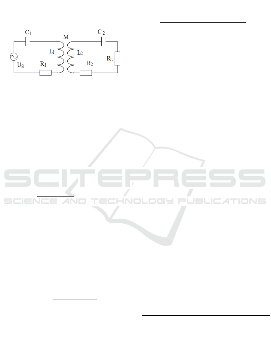
Wireless charging system equivalent diagram is
shown in figure 1 (Junyong et al., 2012). Assuming
that AC power supply voltage for Us, circuit
resonance frequency for ω; The transmitter coil
current i
1
, the impedance of the transmitter coil for
z
1
, transmitter coil equivalent resistance of R
1
, the
transmitter coil inductance for L
1
, transmitter coil on
the capacitor C
1
, accept coil current i
2
, accept the
500
504
Jiang T. and Cheng J.
Speech De-noising based on Wavelet Transform and Genetic Algorithm.
DOI: 10.5220/0006029505040509
In Proceedings of the Information Science and Management Engineering III (ISME 2015), pages 504-509
ISBN: 978-989-758-163-2
Copyright
c
2015 by SCITEPRESS – Science and Technology Publications, Lda. All rights reserved
impedance of the coil as the z
2
, accept coil
equivalent resistance R
2
, accept coil inductance of
L
2
, accept the capacitance on the coil for C
2
, launch
mutual inductance between coils and receive coil for
M; The impedance of the load for R
L
.
Figure 1: Schematic diagram of electromagnetic induction
of WPT.
According to the circuit system diagram can get
circuit impedance equation:
22L22
1111
C1/jLjRRZ
C1/jLjRZ
(1)
By using kirchhoff's voltage law is available:
2
1
2
1
S
Mj
MjZ
0
U
i
i
Z
(2)
By (1) (2) available for current equation:
Mj-
Z
MZZ
U
i
i
2
2
21
s
2
1
(3)
Assumes that the transmitter coil and accept coil at
the same resonance frequency, so
ωL
1
=ωL
2
=1/ωC
1
=1/ωC
2
So the impedance of the
circuit equation:
L22
11
RRZ
RZ
(4)
So the output power of the load of PL and power
supply output power for Ps equation:
L
R
MZZ
2
2
21
2
S
2
L
2
2L
UM
RiP
(5)
2
21
2
S2
1SS
UZ
UP
MZZ
i
(6)
Charging efficiency can be represented as (Ying et
al., 2003):
2
212
L
2
S
L
MZZZ
RM
P
P
(7)
2
L21L2
L
2
MRRRRR
RM
As you can see, the transmission efficiency and M,
ω, R
1
, R
2
, R
L
, including mutual inductance L, M and
coil axial spacing coil radial dislocation S, receiving
coil diameter D, transmitter coil diameter D, closely
related to the coil number of turns N (Huiping and
Xueguan, 2007).
3 MAXWELL MODEL
ESTABLISHMENT
The simulation steps of the 3D Maxwell model
include: select the type of solver, establish the 3D
model, set up the material properties, set the
boundary conditions, set the excitation, the grid
partition, the finite element calculation and the result
processing.
Firstly analyzed the influence of the ferrite of
coil, ferrite in wireless charging coil design has two
main functions: 1) enhance the magnetic field
intensity, reduce the magnetic flux leakage, for flux
1 the low impedance path; Isolation of metal
material to the absorption of the magnetic field; 2)
increase the induction distance, improve the coil
inductance and quality factor (Na et al., 2012).
Different ferrite materials because of the different
permeability, frequency characteristics, has a great
influence on the coil inductor, ferrite loss. Using
Maxwell software model, transmitter coil with TDK
PE22 ferrite materials, the receiver coil choose Fair
Rite Material 44 ferrite materials of the company.
The coil with ferrite shielding and coil without
ferrite shielding are compared, and the simulation
can be seen from the simulation results in table 1
compare, with ferrite shielding winding capacitance
value increased significantly, coupling coefficient
between coil was improved, too.
Table 1: Results comparision μH.
Project Inductance simulation
Accept the coil D1 No ferrite 19
Accept the coil D1 Have a ferrite 29.3
Receiving coil D2 No ferrite 10.2
Receiving coil D2 Have ferrite 21.10
Electromagnetic Induction Wireless Power Transmission Efficiency Research
501
Speech De-noising based on Wavelet Transform and Genetic Algorithm
505
Using software Maxwell model, give a
transmitter coil plus the sine voltage of 12 V, set the
transmitter coil pure impedance is 0.03 Ω,
transmitter coil inductance for 30μH, pure
impedance of receiver coil is 0.3 Ω receiving coil
inductance for 20μH.To analyze the impact of
various factors on the transmission efficiency,
software simulation using the control variable
method. Constant when the choice, according to the
actual application situation, first determine the
receiving coil diameter D is 60 mm, after many
experiments, the other parameters constant finally
selected as shown in table 2.
Table 2: Model parameters.
project Constant value range
Accept coil D1 60 mm -
Transmitter coil
D2
60 mm 30mm-90 mm
Coil radial
dislocation S
0 -10 mm -10 mm
Coil axial spacing
L
0 0-15 mm
The coil number of
turns N
30T 25T-35T
The input voltage
frequency f
150kHz 50 kHz -300 kHz
Load RL 10Ω 1Ω-70Ω
4 THE EXPERIMENTAL
RESULTS
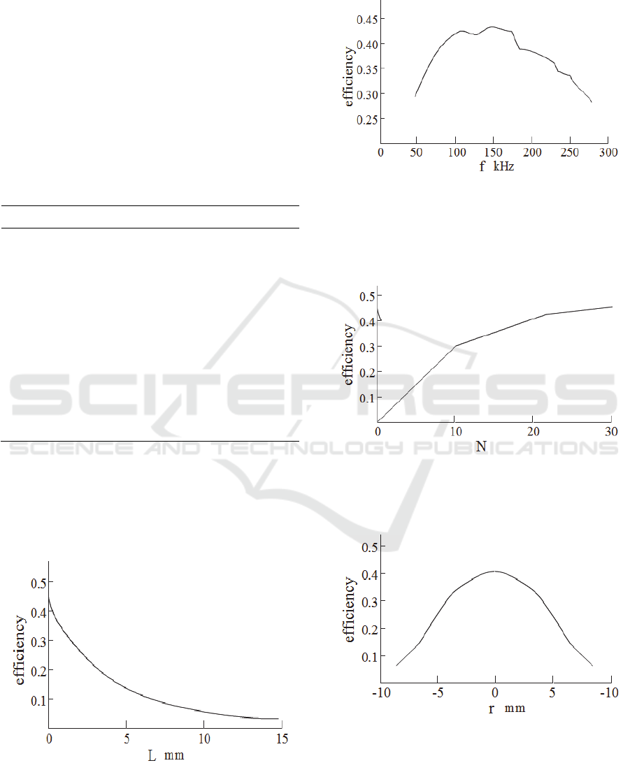
The experimental results are shown in figure 2 ~ 7
Figure 2: Efficiency - coil spacing L.
Coil can be seen from the figure 2 power
transmission efficiency increases with coil distance
L fell quickly, when the spacing of 5 mm, only coil
joint efficiency of 30%.
Figure 3: Efficiency - coil spacing L.
As you can see from figure 3, when fi is less than
100 KHZ, efficiency as the fi and improve, when fi
is greater than 150 KHZ, basic as fi lower and lower
efficiency.
Figure 4: Efficiency - coil spacing L.
You can see from figure 4 efficiency as the coil
number of turns N increases.
Figure 5: Efficiency - coil spacing L.
Can see from figure 5, when the offset r coil
diameter of 0, the receiver and the transmitter coil
equal size, maximum efficiency.
ISME 2015 - Information Science and Management Engineering III
502
ISME 2015 - International Conference on Information System and Management Engineering
506
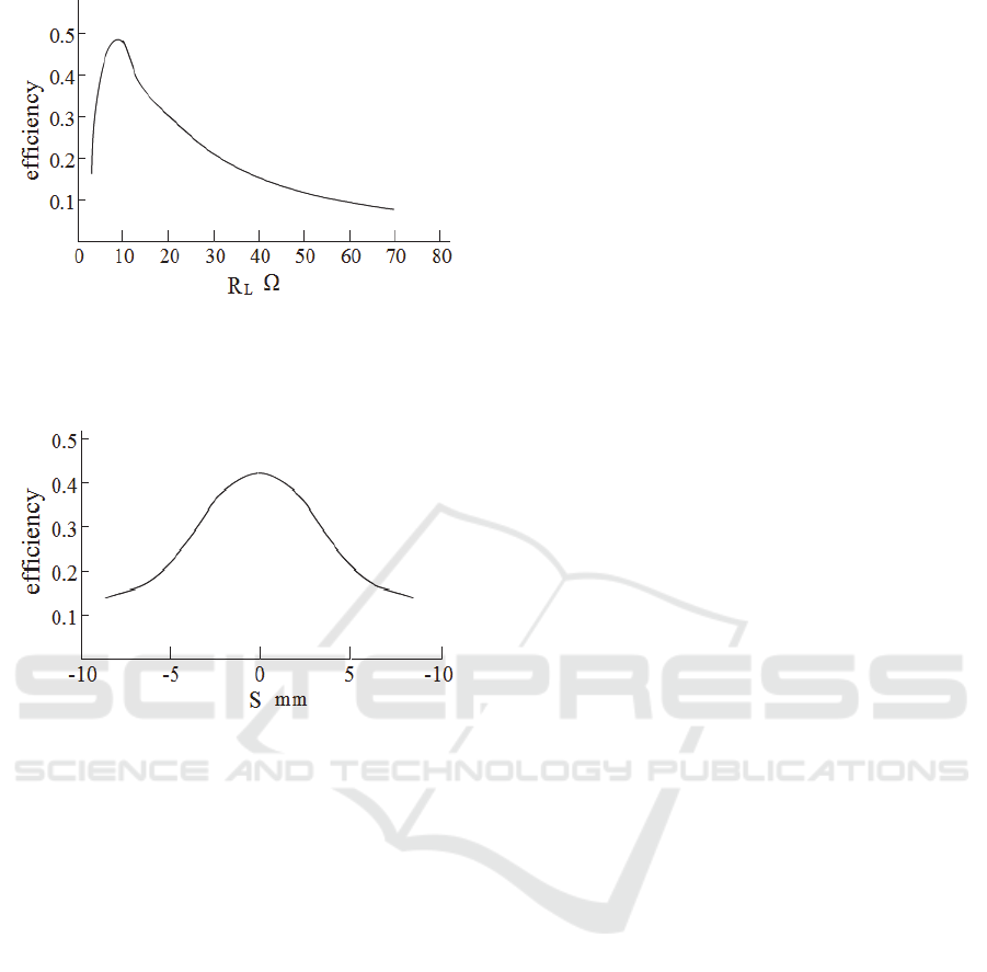
Figure 6: Efficiency - coil spacing L.
Can see from figure 6, when the load RL is 10 Ω
reach maximum efficiency.
Figure 7: Efficiency - coil spacing L
From figure 7, you can see that the transfer
efficiency is very sensitive to the radial dislocation,
the efficiency of the radial dislocation is 5 mm is no
radial position only mistake efficiency 47%.
5 CONCLUSIONS
According to above the results of simulation
analysis, to improve the efficiency of wireless
charging device, should try to shorten the transmitter
coil and the receiving coil axial spacing, the coil as
close to as possible, to control the equipment at the
same time, the working frequency of frequency
range between 100 KHZ to 150 KHZ. In the
conditions allow, as far as possible increase the coil
number of turns; Receiving coil and the transmitter
coil diameter should be equal or close, under the
condition of the simulation, the applicable load for 6
Ω~15Ω, can only meet the demand of small wireless
charging devices; Because the efficiency is sensitive
to the radial dislocation, all must be fixing the
transmitter coil and the location of the receiver coil.
Since the establishment of wireless charging
Union (WPC), wireless charging technology has
been paid more and more attention, how to improve
the efficiency of wireless charging, especially to
improve the efficiency of large power wireless
charging is still a very difficult task (Zhang Bao
Qun, Li Xiang Long, 2015). In this paper, some
suggestions are put forward to improve the
transmission efficiency from the angle of the
electromagnetic induction coil coupling. The
research on the large power promotion will be the
next research direction.
ACKNOWLEDGEMENTS
The authors acknowledge the financial Supported by
a project grant from Huaian technology bureau
(Grand No.HAG2014007).
REFERENCES
Wu Junyong, Wu Jiaxun, Zhang Ning, et al. [J]. 2012.
Experimental study of wireless energy transmission
based on magnetic coupled resonant modern electric
power. In chinese
Wu Ying,Yan Luguang,Xu Shangang. [J] 2003.A New
Contactless Power Delivery System, ICEMS.
Guo Huiping, Liu Xueguan. [M].2007 Electromagnetic
field and electromagnetic wave, Xi'an Electronic and
Science University press, Xi'an. In chinese
Shen Na,Li Chang Sheng,Zhang He. [J].2012.Modeling
and analysis of wireless power transmission system
based on magnetic coupling resonance.Chinese
Journal of Scientific In.strnment.In chinese
Zhang Bao Qun , Li Xiang Long. [J].2012.Current
research and practical analysis of contactless charging
in electric vehicles, Electronic Measurement
Technology. In chinese
Electromagnetic Induction Wireless Power Transmission Efficiency Research
503
Speech De-noising based on Wavelet Transform and Genetic Algorithm
507
