
Non-Stationary Random Wiener Signal Detection with
Multistatic Acoustic System
Volodymyr Kudriashov
Institute of Information and Communication Technologies, Bulgarian Academy of Sciences
25A Acad. G. Bonchev Str., Sofia, Bulgaria
KudriashovVladimir@gmail.com
Keywords: Acoustic signal processing, ultra wideband antenna, localization, imaging.
Abstract: The paper presents detection rule for multistatic reception of the non-stationary acoustic signal. The
detection rule is obtained using maximum likelihood approach. Usually angular beam forming is applied to
microphone array to localize spatially distributed emitters. In the paper, the time difference of arrival
estimates of incoming acoustic emissions are used to localize their sources. The paper proposes wide
frequency band acoustic noise source detection and localization enhancement using multistatic reception
system. The paper shows experimental result on localization of source of wide frequency band emission by
sound pressure imaging. All passband bandwidth of incoming signal is processed simultaneously. The
localization is provided in range-cross range-elevation coordinates. The proposed technique may be suitable
for 4D imaging in non-destructive testing and in ultra-wideband acoustic emitters’ detection and
localization. One of particular applications concerns testing of aircrafts landing regime and health
monitoring of their engines at landing/take off.
1 INTRODUCTION
Detection rule is required to localize source of non-
stationary random Wiener signal in range – cross
range – elevation coordinates (Wentzell 1996, Levin
1969). The rule enables to define threshold level and
the detector block diagram (Rozov 1987, Gusev
1988, Shirman 2007). Existing systems for acoustic
noise source localization use pre-defined range to
generate sound pressure images in cross range –
elevation coordinates. As well, the systems generate
conformal sound pressure images. The generation of
those images uses beamforming techniques based-on
estimates of phase difference of arrival of incoming
signals in predefined frequency passband. The cited
works do not contain detection of incoming signals.
The paper presents rules for detection the signal
against non-stationary random Wiener interference
via bistatic and multistatic acoustic systems as well
as corresponding threshold levels and block
diagrams.
2 PROBLEM STATEMENT AND
SOLUTION
Emission of an object is considered as a realization
of non-stationary random Wiener signal. The signal
frequency bandwidth is wide (Brüel & Kjær Sound
and Vibration Measurement A/S 2009, Christensen
and Hald 2004, Hald et al. 2004). Receivers and
microphones limit it by their bandwidth
B
. The
microphones are significantly spaced. Estimated
parameter is time difference of arrival of incoming
signal to the microphones. The pair of receivers’
output signals are denoted as
t
I
y
and
ty
II
,
correspondingly. The signals may contain the
incoming signal (condition
1A
) or not contain it
(condition
0A
) (Rozov 1987, Gusev 1988 and
Shirman 2007).
The detection rule is derived for the incoming
signal
tx
against mix of interfering signals
t
I
c
,
tc
II
and intrinsic noise of microphones and
receivers
t
I
n
,
tn
II
. The intrinsic noises’ power
49
Kudriashov V.
Non-Stationary Random Wiener Signal Detection with Multistatic Acoustic System.
DOI: 10.5220/0005889300490053
In Proceedings of the Fourth International Conference on Telecommunications and Remote Sensing (ICTRS 2015), pages 49-53
ISBN: 978-989-758-152-6
Copyright
c
2015 by SCITEPRESS – Science and Technology Publications, Lda. All rights reserved
spectral density is
0
N
, for
B
of the equipment. The
signal model is denoted as (Rozov 1987, Gusev
1988 and Shirman 2007):
,
c
tt
I
ct
I
n
x
ttхАt
I
у
,
t
II
ct
II
ntхАt
II
у
Tt 0
(1)
where
tх
,
t
I
n
,
t
II
n
,
t
I
c
and
t
II
c
are
not correlated in pairs;
x
t
and
c
t
are TDOA for the
incoming signal and interference (industrial noise,
multipath propagation on the scene etc.);
is time
delay that introduced to compensate the
x
t
; and
T
is acquisition time.
According to the Wiener process property, the
considered
tх
,
t
I
n
,
t
II
n
,
t
I
c
and
t
II
c
have independent increments those obey normal
distribution (Wentzell 1996, Levin 1969). The exact
time interval, which enables to obtain the normal
distribution of the increments, may be obtained by
further experimental investigations.
The digital signal processing assumption enables
to present the signals (1) as Kotelnikov series with
constant interval
B21
of time sampling. Elements
of the
Y
are the noted above increments
iI
y
,
and
iII
y
,
.
Probability densities of the
Y
are obtained for
the two conditions:
1A
and
0A
, in order to
obtain likelihood ratio
YL
and the detection rule.
At condition
1A
, the incoming signal is
correlated, as well as the interference. Joint
probability density of corresponding samples
iI
y
,
and
iII
y
,
obeys two-dimensional distribution
function of two normally distributed random
variables (Levin 1969). The corresponding
probability density function is obtained based-on
following equality:
k
i
i
A
iII
y
iI
ypAYp
1
1/
,
,
,
1/
,
where
TBk 2
. At the condition
0A
, the
probability density function is obtained similarly. At
the latter condition, no elements of the
Y
are
correlated, except the interference. Relation of
1/ AYp
to
0/ AWp
is the likelihood ratio.
For the technical implementation, natural logarithm
of the obtained
YL
is more appropriate. One
assumes that variances of increments of the noise and
the interference are larger than variance of increments
of the signal. Thereat, one of addends of the obtained
expression do not depends on the incoming signal.
The addend defines the threshold level. Assumption
that variances of increments of the noise are larger
than variances of the interference enables to obtain
weight of the integration in the expression. The
obtained detection rule estimates autocorrelation
functions of increments of signals (1) and their
cross-correlation function. Only the latter depends
on time difference of arrival of incoming signal.
Thus, the detection rule envisages calculating the
expression:
T
dtt
II
y
ІI
kt
I
y
I
k
0
1
(2)
where
III
k
,
define gain values for receivers 1 and
2, correspondingly;
ty
III,
define increments of
the signals (1).
The rule for non-stationary random Wiener
signal detection in bistatic reception system is
obtained (Fig. 1, baseline 1).
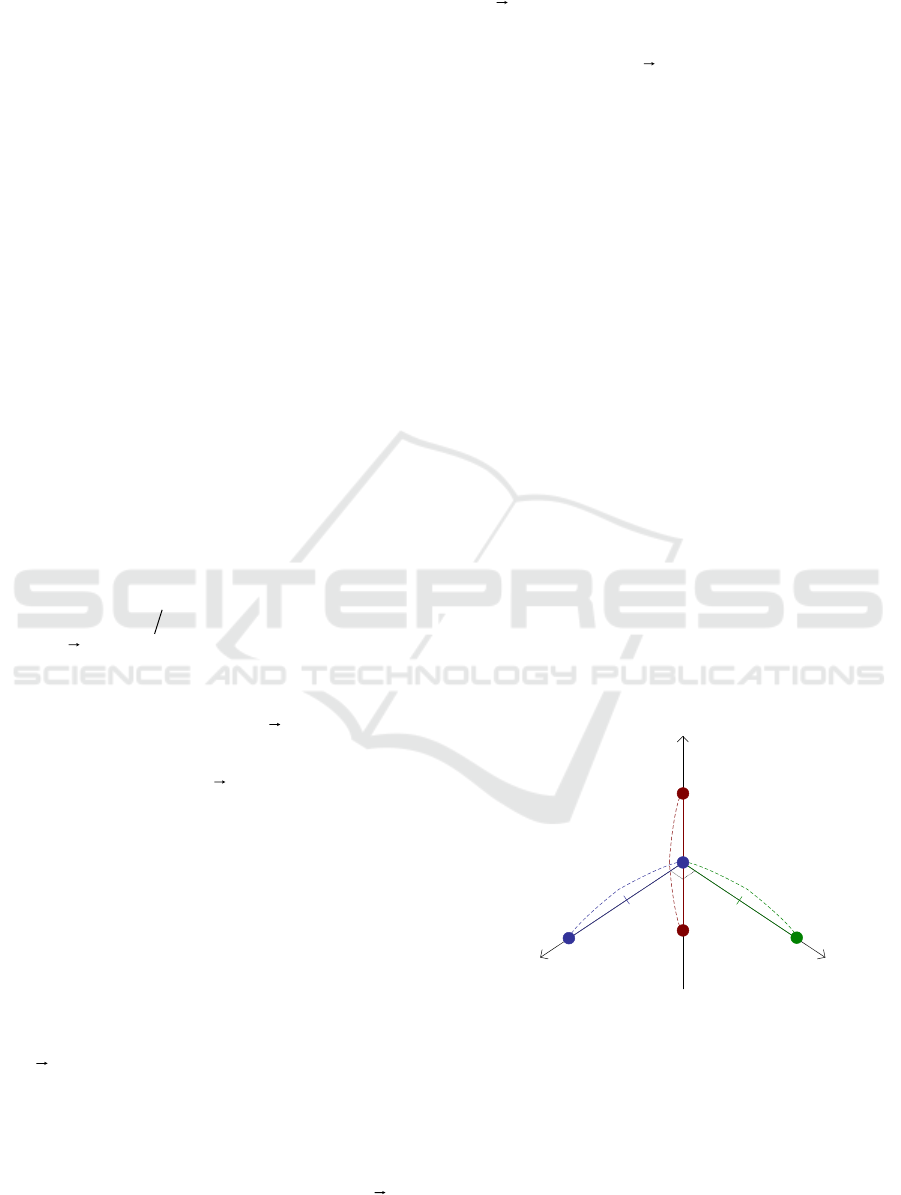
z
x
y
Mic. 2
Mic. 1
Mic. 5
Mic. 4
Mic. 3
Baseline 1Baseline 2
Baseline 3
Figure 1: Basic geometry of the multistatic acoustic
system.
The detection rules for other baselines (Fig. 1)
may be expressed similarly to (2). Output signals of
the bistatic reception systems are denoted as
tu
1
,
tu
2
and
tu
3
, correspondingly.
Fourth International Conference on Telecommunications and Remote Sensing
50

The further detection rule obtainment is similar
to the above one. But, the new
Y
consists of
tu
1
,
tu
2
and
tu
3
samples. The samples are denoted
as
i
u
,1
,
i
u
,2
and
i
u
,3
. At the condition
1A
, the
signal and interference components of the
Y
are
correlated in pairs. Joint probability density of
corresponding samples
i
u
,1
,
i
u
,2
and
i
u
,3
obeys
distribution function of normally distributed random
variables (Levin 1969). At the condition, the
corresponding probability density function is
obtained based-on following equality:
k
i
i
A
i
u
i
u
i
upAYp
1
1/
,3
,
,2
,
,1
1/
.
At the condition
0A
, the samples of
Y
are
independent. Variations of these samples are same.
Relation of the latter probability density functions is
the new likelihood ratio
YL
. One of addends of the
obtained ratio defines the threshold level, as the
signal power in the multistatic system is low. Other
one addends sum of power estimates from the three
considered bistatic systems (Fig. 1). All possible
cross-baseline cross correlation functions are
subtracted from the latter addend. The last addend
provides multiplication of power values of output
signals of the bistatic systems. The latter is agreed to
detection quality at limited number of
samples (Shirman 2007). The input signals squaring
is valuable for small signal-to-noise-plus-
interference ratio at outputs of the bistatic systems.
Spatial localization of the emission source is utilized
by the considered multistatic system (Fig. 1) by the
latter addend:
Т
dttиktиktиk
0
2
33
2
22
2
11123
(3)
where
і
k
are gain values of corresponding bistatic
systems 1-3. All intermediate results and threshold
level expression were dropped down.
The obtained requires to estimate TDOA of the
signal by each bistatic system and to provide further
calculation according to (3), for each node of spatial
grid.
The non-stationary random Wiener signal
detection rule for three bistatic systems is obtained
according to the maximum likelihood method with
respect to the threshold level.
3 EQUIPMENT OF THE
ACOUSTIC CAMERA
Acoustic camera, manufactured by Brüel & Kjaer
(Sound and Vibration Measurement A/S) is used.
The camera uses 18 microphones type 4958, 12-
channel and 6-channel input modules type 3053-B-
120 and 3050-B-060, correspondingly. The acoustic
camera includes Pulse LabShop software. The latter
was used to transfer the multichannel equipment
output signals for further post-processing.
The microphones dimensions are: 34 mm long, 7
mm diameter. Sensitivity of the microphones is
11.2 mV/Pa. Operating temperature range of the
microphones is from 10˚C to +55˚C. The
microphones dynamic range is from 28 dB to
140 dB. The microphones have CCLD preamplifier
with transducer electronic datasheet (TEDS - IEEE
1451.4 V.1.0).
Both input modules support TEDS transducers
and deliver REq-X technology, which flattens the
transducers frequency responses by “mirroring”
them. These input modules are mounted in 5-slot
Mainframe LAN-XI type 3660-C-000 with battery
module type 2831. The 3050-B-060 input module
delivers Dyn-X technology that expands its dynamic
range depending on exact signal quantization and
bandwidth.
The acoustic camera upper frequency is 25.6 kHz
and its quantization rate is about 65 kHz. The signals
are synchronized using IEEE 1588 Precision Time
Protocol.
The camera calibration may be provided in
advance to assure precision of sound pressure
estimates. The acoustic camera incudes hardware
and software for the calibration. The portable
calibrator is battery operated. The calibration
frequency is 251.2 Hz. Pistonphone calibrator type
4228 with external barometer satisfies ANSI S1.40-
1984 and IEC 942 (1988) Class 0L. The calibrator
has following adaptors: DP-0775 for sequential
calibration of the microphones and adaptor WA-
0728-W-003 for calibration of groups of 6-
microphones. The calibrator can be used over a wide
range of temperature, humidity and pressure while
still maintaining high accuracy.
Optic camera with resolution 640×480 pixels and
microphones in 0.33 m slice wheel array of the
acoustic camera are mounted on 3D tripod head
Non-Stationary Random Wiener Signal Detection with Multistatic Acoustic System
51
Manfrotto 229 and tripod Manfrotto 058B. The load
capacity of both head and tripod is 12 kg (safety
payload).
The acoustic camera data transfer cables limit
spatial separation between the equipment blocks.
The acoustic camera consists of three main blocks: a
microphone array with optic camera, input modules
in a frame and a laptop with software. Cable harness
type WL1297-W-004 2013W21 with length ~4.5 m
limits separation between the microphone array and
the mainframe. Both optic camera USB cable with
length ~6.3 m and LAN cable type AO1450-D-020
2013W13 with length ~2 m limit separation between
the mainframe and laptop with the acoustic camera
software. The main features of the laptop type 7201-
E-GB2 (Dell Latitude E6430) are listed below:
E6430 CPU, 6 GB RAM, 1 TB HDD, Wi-Fi,
Ethernet 1 Gb, DVD-RW.
The acoustic camera hardware and software
modules are supplied with full documentation
(instruction manual, specifications). Acoustic
images may be generated using Array Acoustics
Post-processing (Version 17.1.2.308). Measurement
data may be collected using Pulse LabShop
(Customized Solution Version 17.1.2). Other
existing software and drivers are not listed in this
work.
4 DETAILS AND RESULT OF
EXPERIMENT
Experiment is focused on localization of acoustic
noise emission source with the multistatic system
(Fig. 1). Microphone 1 is placed in the origin of
Cartesian coordinate system. Baselines equal to 1 m.
Emitter coordinates in the field of view are as
following: range 1 m, cross range -0.8 m and
elevation 0.15 m. Center frequency of the incoming
signal is about 5 kHz and bandwidth of the signal is
about 10 kHz. The latter corresponds to TDOA
resolution of about 3.5 cm, at a baseline.
The signal processing contains multiplication of
the bistatic systems output signals normalized
squared. The amplitude calibration of the Acoustic
Camera was carried out in advance. Obtained results
are displayed in logarithmic scale (Fig. 2). Multipath
propagation inside a typical office room affects
equality of responses of the bistatic systems. Thus,–
6 dB threshold is applied to the results. The
normalization is not present in (3). Slight irregularity
of responses of three bistatic systems (Fig. 2) is
affected by insufficiently small pixel size.
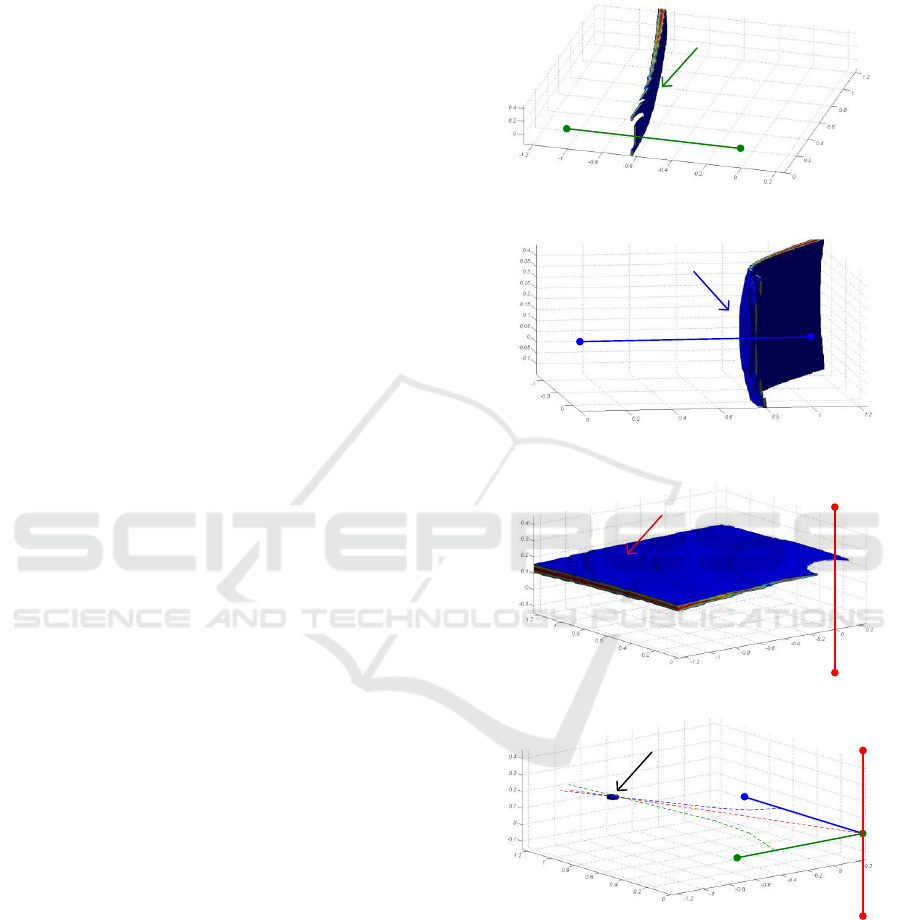
The result shows opportunity to localize the
emission source with the presented approach (3).
Baseline 1
Hyperb. 1
Cross Range, m
Range
,
m
Elevation, m
a)
Baseline
2
Hyperb. 2
Range, m
Cross
Range, m
Elevation, m
b)
Baseline 3
Hyperb. 3
Cross Range, mRange, m
Elevation, m
c)
Baseline
1
Hyperb
.
1
Baseline
2
Hyperb
.
2
Baseline 3
Hyperb
.
3
Cross Range, mRange, m
Elevation, m
The emission source response
d)
Figure 2: Acoustic images generated using the shown
bistatic systems and according to the proposed approach
using the multistatic system.
Fourth International Conference on Telecommunications and Remote Sensing
52

5 CONCLUSIONS
Newly developed detection rules of non-stationary
random Wiener signal against such interference are
proposed for bistatic and multistatic acoustic
systems. The rules enable to define corresponding
threshold levels and technically feasible block
diagrams. The four-site system is considered for
spatial localization of acoustic emission source. The
proposed approach uses time difference of arrival
estimates of incoming signal instead of its phase
difference of arrival estimates to localize the source.
Test source passband bandwidth about 10 kHz is
processed simultaneously, in the experiment. Further
implementation of the approach is promising for
wideband acoustic noise source localization.
ACKNOWLEDGEMENTS
The research work reported in the paper was partly
supported by the Project AComIn "Advanced
Computing for Innovation", grant 316087, funded by
the FP7 Capacity Programme (Research Potential of
Convergence Regions).
REFERENCES
Wentzell, A.D., 1996. Course of the theory of random
processes. Science. Moscow. In Russian.
Levin, B.R., 1969. Theoretical bases of statistical radio
engineering, Vol. 1. Soviet Radio. Moscow. In
Russian.
Rozov, A.K., 1987. Detection of signals in non-stationary
hydroacoustic conditions. Shipbuilding. Leningrad. In
Russian.
Gusev, V.G., 1988. Systems for space-time processing of
hydroacoustic information. Shipbuilding. Leningrad.
In Russian.
Shirman, Ya.D. (ed.), 2007. Radio Electronic Systems:
Fundamentals of Theory and Design. Soviet Radio.
Moscow, 2nd edition. In Russian.
Brüel & Kjær Sound and Vibration Measurement A/S.,
2009. Brüel & Kjaer Product data. Brüel & Kjær.
Nærum.
Christensen, J.J., Hald J, 2004. Beamforming. In Brüel &
Kjaer Technical Review No. 1. Brüel & Kjær. Nærum.
Hald J., Ishii Y., Ishii T., Oinuma H., Nagai K.,
Yokoyama Y. and Yamamoto K., 2012. High-
resolution Fly-over Beamforming Using a Small
Practical Array. Brüel & Kjaer Technical Review No.
1. Brüel & Kjær. Nærum.
Non-Stationary Random Wiener Signal Detection with Multistatic Acoustic System
53
