
Towards Multi-functional Robot-based Automation Systems
Andreas Angerer
1
, Michael Vistein
1
, Alwin Hoffmann
1
, Wolfgang Reif
1
, Florian Krebs
2
and Manfred Schnheits
2
1
Institute for Software & Systems Engineering (ISSE), University of Augsburg, Augsburg, Germany
2
Center for Lightweight Production Technology, Institute of Structures and Design,
German Aerospace Center, Stuttgart, Germany
Keywords:
Cooperating Robots, Industrial Automation and Robotics, Robot Programming, Modelling and Simulation.
Abstract:
Multi-functional robot cells will play an important role in smart factories of the future. Equipped with flexible
toolings, teams of robots will be able to realize manufacturing processes with growing complexity. However, to
efficiently support small batch sizes and a multitude of process variants, powerful software tools are required.
This paper illustrates the challenges that developers face in multi-functional robot cells, using the example of
CFRP production. The vision of a new programming environment for such future flexible automation systems
is sketched.
1 INTRODUCTION
According to the International Federation of Robotics
(2014), the automotive industry is currently the
largest operator of industrial robots. This is mainly
due to the large batch sizes and, thus, a high num-
ber of repetitive tasks which allows for a more eco-
nomic integration of robots compared to other indus-
tries. However, there is a trend to apply robotic sys-
tems also for small batch production and for com-
plex manufacturing processes (cf. euRobotics aisbl,
2014). Especially with the Internet of Things and
Services and strategic initiatives such as Industry 4.0
in Germany (cf. Kagermann et al., 2013), the idea
of smart factories with intelligent machinery – re-
ferred to as cyber-physical systems (cf. Geisberger
and Broy, 2012) – and a highly customized produc-
tion is emerging. The products incorporate the knowl-
edge of how they need to be processed and, moreover,
they communicate directly with the machinery. As
cyber-physical systems, they know their skills and of-
fer them as services in a smart factory.
From our point of view, multi-functional robot
cells will play an important part in future smart facto-
ries. Industrial robots are flexible machines that can
perform a broad variety of tasks using different end-
effectors. Moreover, dynamic teams of cooperating
robots can together handle complex tasks if required.
Until today, there is a strong focus on knowledge-
based manufacturing systems or cyber-physical sys-
tems consisting of a single robot. However, when re-
garding dynamic teams of robots, the available skills
depend on the composition of the team. Cyber-
physical systems must be able to occasionally form
a new system with an extended set of skills and ser-
vices which poses new challenges for research.
The production of carbon fiber-reinforced plas-
tics (CFRP) is an interesting example where multi-
functional robot cells are important. CFRPs are be-
coming more and more important for many modern
products, e.g. for airplanes or helicopters, but also for
the automotive industry. Today, the production is of-
ten done manually, which is a very tedious and stren-
uous task, therefore it is worthwhile to automate this
process. However, the dimensions of CFRP parts can
vary tremendously depending on the product: Some
aircraft structures can be only a few centimeters in
size whereas others can be in the range of several
dozens of meters. Thus, a single industrial robot in
a static, fixed configuration will not always be suffi-
cient for handling the parts.
This paper introduces the challenges as well as a
possible road map for modeling, programming and
simulating dynamic robot teams in multi-functional
cells. Section 2 delivers a detailed view of both the
production process for CFRP and the multi-functional
robot cell built at the Center for Lightweight Pro-
duction Technology (ZLP) of the German Aerospace
Center (Deutsches Zentrum f
¨
ur Luft- und Raumfahrt,
DLR) in Augsburg. In Section 3, the current ap-
438
Angerer A., Vistein M., Hoffmann A., Reif W., Krebs F. and Schönheits M..
Towards Multi-functional Robot-based Automation Systems.
DOI: 10.5220/0005573804380443
In Proceedings of the 12th International Conference on Informatics in Control, Automation and Robotics (ICINCO-2015), pages 438-443
ISBN: 978-989-758-123-6
Copyright
c
2015 SCITEPRESS (Science and Technology Publications, Lda.)
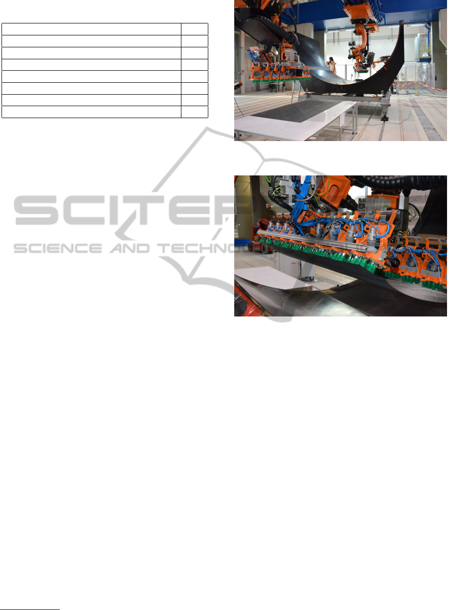
Table 1: Cutpiece distribution for the demonstration pro-
cess.
Cutpiece class #
Skin “tile” (regular shape) 40
Skin “tile” (irregular on margins) 16
Frame thickness extension (regular shape) 40
Frame thickness extension (irregular) 16
Stringer base (large) 48
Stringer base (small) 48
Sum 208
proaches are described and challenges for applica-
tion development in such large scale environments are
identified. Novel approaches for efficient software de-
velopment for large teams of robots and peripheral de-
vices are introduced in Section 4. The paper is con-
cluded with Section 5.
2 CASE STUDY
To motivate the challenges that have to be faced in
multi-functional robot cells, we would like to address
the automated production of CFRP structural compo-
nents for aerospace applications. Many processes for
the production of CFRPs exist such as advanced fiber
placement, resin transfer molding, or vacuum assisted
resin infusion (VARI). An overview over these tech-
niques can be found in Baker et al. (2004). In the fol-
lowing, the VARI process will be shortly introduced
to understand the process requirements. A first auto-
mated solution is described afterwards.
2.1 Vacuum Assisted Resin Infusion
The VARI process basically uses dry textile cutouts
laid into a mold at specific positions. Afterwards the
mold is sealed with an airtight foil and other auxil-
iary materials. The whole layup is then evacuated and
subsequently infused with resin. To fully leverage the
weight saving potential of CFRPs, fibers are mainly
oriented along the major axis of tensile loads. In other
words, more material is placed in areas where high
loads are expected and less in other areas. Ultimately,
this leads to a very complex design of cutouts – often
referred to as cutpieces – in which many cutpieces
are unique within the layup. The whole layup is doc-
umented in a plybook
1
which specifies the shape of
each cutpiece and where it should be placed in the
layup. In aerospace applications, these plybooks usu-
ally contain hundreds of individual cutpieces.
1
A ply is a set of cutpieces forming a layer in a layup.
Figure 1: The experimental setup for the layup in the multi-
functional cell.
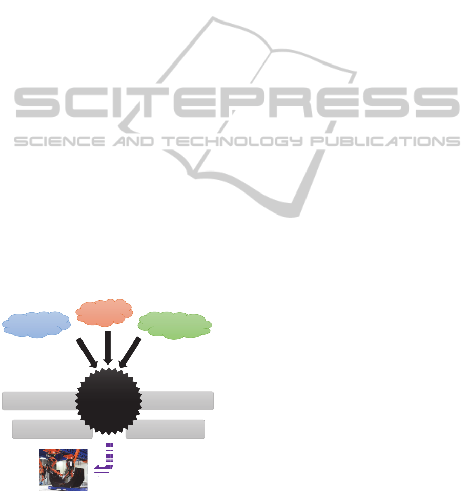
Figure 2: Both robots gripping a cutpiece.
2.2 Experimental Setup
In 2014, the DLR in Augsburg implemented an au-
tomated demonstration for this process on site, using
a section of an aircraft fuselage. This component is
basically a half-cylinder with a radius of ∼1.8 meters
and roughly a length of 2.5 meters. To illustrate the
automation process, a simplified plybook was created
consisting of 208 mostly uniform cutpieces. Table 1
summarizes the different ply classes. After plybook
design, a rough layout of the process in the robot cell
was drafted. The DLR’s multi-functional cell (Krebs
et al., 2014) was chosen as a platform.
This cell is intended for the evaluation of auto-
mated production processes for CFRP parts and con-
sists of two industrial 6-DOF arms on a common lin-
ear track in overhead configuration, and three XYZ-
portals spanning a workspace of roughly 30 x 15 x 7
meters. For this application, only the two central in-
dustrial arms were used (cf. Figure 1). The validation
of cooperative layup of single cutpieces was one of
the main objectives of this setup. Therefore the larger
cutpieces were handled using the KUKA.RoboTeam
technology which allows multiple robots to act coop-
TowardsMulti-functionalRobot-basedAutomationSystems
439

eratively. Three modes of operation are possible:
• Synchronized start: all robots start a process step
at the same time
• Synchronized motion: both the start and the finish
times of a step occur simultaneously for all robots
• Motion cooperation: one robot acts as a master
while the other robots follow in a geometrically
linked fashion
On each end-effector, a gripper was mounted that was
able to hold an edge of the fabric (cf. Figure 2). One
gripper was additionally equipped with a system to
measure the layup quality using a laser scanner.
2.3 Process Description
In a nutshell, the process is a pick&place application
that requires the cutpieces to be picked up from a ta-
ble and positioned into the mold at the proper coordi-
nates for each cutpiece. At the beginning, both robots
pick up each side of the cutpiece with their vacuum
grippers from a table together using a synchronized
motion. The following motions transfer the robots
into safe a position over the mold and include a mo-
tion of the linear track. Although this motion needs
to be synchronized as well, this cannot be carried out
by KUKA.RoboTeam since linear tracks are not fully
supported. A workaround was found by starting both
robot motions at the same time and letting them travel
the for same distance. After reaching the safe posi-
tion, the robots are geometrically linked and the mas-
ter robot leads the slave to a position just before layup.
Then, breaking the link again, each robot moves in a
synchronized motion to its individual target position,
making final adjustments along the way to compen-
sate for small deformations in the mold.
When both robots are in place, heaters are ex-
tended to melt the thermoplastic binder and temporar-
ily bond the cutpiece. After a ply has been laid up
completely, the robots move back into the safe posi-
tion. The robot without the laser scanner moves out
of the mold. After that, the measurement is started by
the second robot to verify that all cutpieces have been
positioned correctly according to the plybook. As-
suming the measurement showed no anomalies, both
robots move back into the starting configuration and
repeat the cycle until all plies have been laid.
2.4 Programming the Process
Currently available offline programming toolchains
like DELMIA (Dassault) and Process Simulate
(Siemens) lack proper support for cooperating robots
and could thus not be used directly for programming
the process. Instead, a hybrid approach was em-
ployed: The transfer from the table to the mold was
done using a classical teach-in process to define fixed
motions for both of the robots. Picking up the cut-
pieces as well as layup onto the mold was done by
using parameterized robot programs. The parameters
– mainly the gripping and target points – were gener-
ated in CPD
2
and exported manually by the program-
mers. Controlling the cooperation of the robots had to
be done by manually inserting appropriate commands
into the robot programs.
In sum, a lot of steps had to be done manually due
to the lack of appropriate support in CAD and offline
programming tools. Additional difficulties had to be
solved in dealing with KUKA.RoboTeam and online
programming as mentioned by Larsen et al. (2014).
While this experiment – dealing only with a minor
number of variations – already formed a challenge, it
is obvious that this approach will not scale to a real
world example with a multiple of individual plies.
3 CHALLENGES
Multi-functional cells like the DLR MFZ are able to
handle complex, fast-changing processes with rather
small lot sizes. The key ingredient are different types
of manipulators with the ability to cooperate, vary-
ing end-effectors as well as additional tools and fit-
tings. But still planning, programming and control-
ling processes in such robot cells remains a difficult
issue. The problem can be divided into two major
challenges, as outlined below.
3.1 Modeling, Planning and Simulation
Processes with a very high complexity and variability
cannot be fully planned and programmed manually.
Developers of the system software need tools for as-
sisted, semi- or fully automated planning of all tasks
involved in a process. Moreover, mapping tasks to a
multi-functional robot cell and determining an appro-
priate combination of robot arms, end-effectors and
sensors to reliably execute a certain task is a chal-
lenge that nowadays requires skilled and experienced
human experts.
In sum, we see challenges in the following areas:
• modeling complex processes with a large number
of interdependent tasks,
• modeling devices in a multi-functional cell and
their abilities (e.g. manipulators, end-effectors,
2
Composites Part Design, an extension for Dassault’s
CAD software CATIA.
ICINCO2015-12thInternationalConferenceonInformaticsinControl,AutomationandRobotics
440

actuators, sensors, . . . ),
• modeling interaction of the devices (e.g. team and
un-team multiple manipulators on the fly),
• representing capabilities of single manipulator-
endeffector combinations,
• representing capabilities of teams of manipulators
and end-effectors
• (semi-)automated planning of process execution
in multi-functional robot cells,
• simulation and qualitative analysis of complex
processes in multi-functional cells.
For defining robot paths based on CAD data, there
exist various toolchains that are used in industry as
well as academia today. A prominent example is
the combination of Dassault Systeme’s CATIA and
DELMIA, sometimes combined with cenit’s FAST-
SURF. DELMIA can be used to perform virtual teach-
in of robot motions based on CAD input from CATIA.
FASTSURF adds support for motions along more
complex surfaces and furthermore integrates simula-
tion and analysis functionality geared towards con-
crete processes like painting. However, those tools
are rather focused on modeling single tasks and reach
their limits when it comes to modeling complex pro-
cesses with hundreds of sub-tasks like in the VARI
process. Furthermore, the support for robot teams in-
cluding different cooperation patterns is rather lim-
ited. In research, various single aspects that are rel-
evant for multi-robot systems have been treated, like
collision detection and path planning for multi-robot
systems (cf. Mediavilla et al., 1998; Larsen et al.,
2014). Only recently, research started to address the
idea as well as basic challenges regarding off-line pro-
gramming environments for multi-robot systems (cf.
Basile et al., 2012; Gan et al., 2013).
On the other hand, a lot of research has been done
in the area of process description as such as well as
(automatic) decomposition of processes into tasks (cf.
Thomas and Wahl, 2001; Ou and Xu, 2013; Huck-
aby et al., 2013). This has also been applied to the
robotics domain and has been combined with mod-
eling of devices, end-effectors and their skills (cf.
Pfrommer et al., 2013; Stenmark and Malec, 2013;
Michniewicz and Reinhart, 2014). However, research
in these areas has been focused largely on single robot
systems, and the additional challenges induced by co-
operating robot teams have not been treated in-depth.
3.2 Deployment to Real-world Systems
Similar to the physical actuators and end-effectors
in multi-functional cells, also the controller struc-
ture is very heterogeneous. Robot controllers mostly
are programmed using proprietary, manufacturer-
dependent programming languages and add-ons (e.g.
for robot cooperation). Devices utilize various tech-
nologies like field bus systems (e.g. Profinet, De-
viceNet, Ethercat) and ethernet-based protocols to
communicate. Often PLCs are used to build topolo-
gies and also to implement superordinated logic, of-
tentimes real-time deterministic and safety-critical
logic. But the PLCs typically are programmed using
proprietary tools and languages in turn.
In classical offline-programming scenarios, code
generation is often used to derive executable artifacts
from models for the target platforms (cf. Feldmann
et al., 2013; Stenmark et al., 2014). Even in a simple
robot cell, this has lots of disadvantages:
• many manual steps, e.g. exported robot programs
typically have to be moved to the robot controller
• shortcomings in flexibility, e.g. communication to
other devices is often done through generated I/O
commands in the robot program, this mostly lacks
good support for changes e.g. in I/O mapping
• ensuring overall consistency is imposed on the
user
In a multifunctional, reconfigurable robot cell, this all
gets even more tedious and error-prone to support all
of the different target platforms present.
4 TOWARDS EFFICIENT
SOFTWARE DEVELOPMENT
In order to efficiently develop software for multi-
functional robot cells, progress is needed on various
levels. This section presents areas that need be pushed
forward from our point of view (cf. Figure 3).
First of all, it is necessary to model the manufac-
turing process and break it down into single tasks.
It might be necessary to decompose tasks into fur-
ther sub-tasks. Dependencies among tasks need to be
modeled in order to determine a feasible order for ex-
ecution and parallelization. For example, in the VARI
process, the cutpieces may be produced all in parallel,
while the layup process obviously requires a certain
order of tasks. Each of the tasks has certain require-
ments that have to be fulfilled for successful execu-
tion. For example, cutpieces may be bent only to a
certain degree in order not to damage the fibers, which
has to be ensured during handling. Furthermore, a
maximum position tolerance has to be respected when
the cutpieces are laid into a mold. While some of
those requirements are mandatory for successful pro-
duction, others can be met with a certain tolerance,
TowardsMulti-functionalRobot-basedAutomationSystems
441
which influences the result quality. To judge the re-
sulting quality, the process model has to introduce
metrics for quality, which allows to predict quality of
the final result. For more accurate predictions, empiri-
cal values (e.g. known inaccuracies) should be usable
for extrapolation.
In order to map a manufacturing process to the ca-
pabilities of a multi-functional robot cell, a thorough
model of robot teams and tools is required. This
model must be able to describe not only the charac-
teristics and skills of a single robot with a specific
end-effector, but also that of different combinations
of devices, i.e. different combinations of robot arms
and end-effectors and in particular the combination of
multiple robot arms to teams as required by the task.
When multiple robot arms form a team, there are dif-
ferent cooperation patterns that fit various kinds of
tasks (e.g., uniform motion or motion relative to other
team members’ motions). The type of cooperation
pattern has an influence on how the team needs to be
represented by the model. In robot teams, different
constraints apply to the allowed operations, for exam-
ple due to the workspace of the single members or due
to physical capabilities like maximum velocities and
accelerations. On the other hand, those constraints
can depend on the initial configurations of the mem-
bers in the team. Thus, the formation of teams plays
an important role: Certain preconditions have to be
met in order to create a team from single robots.
Based on the manufacturing process model, a
CAD model of the robot cell and the model of robot
teams and tools, a unified programming environ-
ment for multi-functional robot cells becomes fea-
sible as a basis for mapping domain-specific pro-
simulate process
measure
process quality
assist in
offlineteaching
assign tasks
to robot teams
programming
environment
programming
environment
dynamic robot
team model
process model
Ͳ skills
Ͳ cooperation patterns
Ͳ constraints
Ͳ team formation
Ͳ task decomposition
Ͳ task dependencies
Ͳ task requirements
Ͳ quality metrics
deployment to realsystem
CADmodel
Figure 3: Process, CAD and robot team models should be
unified in a programming environment to assist software de-
velopment for multi-functional robot cells.
duction processes to concrete manufacturing cells.
By analyzing task composition and dependencies and
matching task requirements with robot (team) skills,
the programming environment can assist users in as-
signing tasks to robot teams. To design concrete op-
erations of a robot (team) required for a certain man-
ufacturing task, the programming environment must
assist users in offline teaching. Conventional on-line
teaching techniques are time-consuming and expen-
sive already for systems with single robots. Due to
constraints and physical dimensions of robot team se-
tups, on-line teaching becomes infeasible.
The assignment of tasks to robot teams and the
concrete task realization by robot team operations has
a strong influence on the quality of the process. A
programming environment should allow for measur-
ing the resulting process quality based on the quality
metrics inherent to the process model and the charac-
teristics of the robots and end-effectors. In this con-
text, the ability to simulate a concrete process in a
multi-functional cell is of great importance. Simula-
tion should be accurate enough to roughly conclude
about the process quality and to compare it among
different variants of a process. Simulation should
furthermore support user-defined parameters for in-
terrupting and replaying, similar to the use of break-
points in software debugging.
A crucial factor for the effectiveness of the pro-
posed offline programming system is the transition
from simulation to the real-world system. As men-
tioned before, code generation from models is the
predominant approach nowadays. In multi-functional
robot cells with complex end-effectors and very het-
erogeneous controllers, the effort for developing code
generators increases dramatically. Not only a vari-
ety of target platforms (robot controllers, tool con-
trollers, PLCs, ...) has to be supported, but also the
semantic consistency of the resulting code has to be
ensured. In order to match the required hard real-time
requirements in a cooperating robot team, further as-
pects like communication latencies have to be con-
sidered. Furthermore, modifications to the generated
code are often hard to re-integrate into the models, re-
quiring those modifications to be made over and over
again after code generation. From our point of view,
this “classical” code generation approach is no longer
feasible for multi-functional robot cells. Instead, a
shift towards open, standardized and configurable in-
terfaces of the different devices is necessary. Those
interfaces should reflect more closely the semantic
concepts of the process model. Thus, it might be-
come feasible to directly execute the models instead
of generating code, which would allow for a seamless
transition from simulation to real-world operation.
ICINCO2015-12thInternationalConferenceonInformaticsinControl,AutomationandRobotics
442

First steps towards the proposed programming en-
vironment have already been made. In a first setup,
a single robot and multiple end-effectors have been
used. Based on a process model and a CAD model of
the robot cell, a semi-automatic generation of a feasi-
ble process flow is possible, including offline teaching
and simulation. Details on the architecture and setup
can be found in N
¨
agele et al. (2015).
5 CONCLUSION
This work illustrated the challenges that develop-
ers face when complex manufacturing processes
should be realized with a multi-functional robot cell.
The Multi-Functional Cell located at the DLR ZLP
in Augsburg is one of the world’s biggest multi-
functional robot cells in operation today and can be
seen as a prototype of what is yet to come accord-
ing to current research agendas. Based on a particu-
lar CFRP manufacturing process, the main challenges
that need to be solved were explained. The vision of a
programming environment for multi-functional robot
cells that unifies process, CAD and robot team models
was presented. By future joint research, the Univer-
sity of Augsburg and the DLR Center for Lightweight
Production will strive to realize this vision.
ACKNOWLEDGEMENT
The demonstration depicted in Section 2 was made
possible with the help and support of Andreas Buch-
heim, Somen Dutta, Mona Eckardt, Lars Larsen,
Thomas Schmidt, and Alfons Schuster of the DLR.
REFERENCES
Baker, A. A., Dutton, S., and Kelly, D. (2004). Composite
Materials for Aircraft Structures. American Institute
of Aeronautics & Astronautics.
Basile, F., Caccavale, F., Chiacchio, P., Coppola, J., and Cu-
ratella, C. (2012). Task-oriented motion planning for
multi-arm robotic systems. Robotics and Computer-
Integrated Manufacturing, 28(5):569 – 582.
euRobotics aisbl (2014). Strategic research agenda for
robotics in Europe 2014 – 2020.
Feldmann, S., Loskyll, M., Rosch, S., Schlick, J., Zuhlke,
D., and Vogel-Heuser, B. (2013). Increasing agility
in engineering and runtime of automated manufactur-
ing systems. In 2013 IEEE Intl. Conf. on Industrial
Technology, pages 1303–1308.
Gan, Y., Dai, X., and Li, D. (2013). Off-Line Program-
ming Techniques for Multirobot Cooperation System.
In Intl. J. of Adv. Robotic Systems. InTech Europe.
Geisberger, E. and Broy, M., editors (2012). Integrierte
Forschungsagenda Cyber-Physical Systems. acatech.
Huckaby, J., Vassos, S., and Christensen, H. I. (2013). Plan-
ning with a task modeling framework in manufactur-
ing robotics. In 2013 IEEE/RSJ Intl. Conf. on Intelli-
gent Robots and Systems, pages 5787–5794.
International Federation of Robotics (2014). World
Robotics – Industrial Robots 2014. VDMA Verlag.
Kagermann, H., Wahlster, W., and Helbig, J. (2013). Rec-
ommendations for implementing the strategic initia-
tive INDUSTRIE 4.0. Final report of the Industrie 4.0
Working Group, acatech.
Krebs, F., Larsen, L., Braun, G., and Dudenhausen, W.
(2014). Design of a multifunctional cell for aerospace
CFRP production. The Intl. J. of Adv. Manufacturing
Technology, pages 1–8.
Larsen, L., Kim, J., and Kupke, M. (2014). Intelligent path
planning towards collision-free cooperating industrial
robots. In 11th Intl. Conf. on Informatics in Control,
Automation and Robotics.
Mediavilla, M., Fraile, J., Peran, J., and Dodds, G. (1998).
Optimization of collision free trajectories in multi-
robot systems. In Robotics and Automation. Proceed-
ings. 1998 IEEE Intl. Conf. on, volume 4, pages 2910–
2915 vol.4.
Michniewicz, J. and Reinhart, G. (2014). Cyber-physical
robotics – automated analysis, programming and con-
figuration of robot cells based on cyber-physical-
systems. Procedia Technology, 15:567–576.
N
¨
agele, L., Macho, M., Angerer, A., Hoffmann, A., Vistein,
M., Sch
¨
onheits, M., and Reif, W. (2015). A backward-
oriented approach for offline programming of com-
plex manufacturing tasks. In The 6th Intl. Conf. on
Automation, Robotics and Applications.
Ou, L.-M. and Xu, X. (2013). Relationship matrix based
automatic assembly sequence generation from a CAD
model. Computer-Aided Design, 45(7):1053 – 1067.
Pfrommer, J., Schleipen, M., and Beyerer, J. (2013). PPRS:
Production skills and their relation to product, pro-
cess, and resource. In 2013 IEEE Intl. Conf. on
Emerging Tech. & Factory Automation, pages 1–4.
Stenmark, M. and Malec, J. (2013). Knowledge-based in-
dustrial robotics. In 12th Scandinavian Conf. on Arti-
ficial Intelligence, pages 265–274.
Stenmark, M., Malec, J., and Stolt, A. (2014). From high-
level task descriptions to executable robot code. In 7th
IEEE Conf. on Intelligent Systems, pages 189–202.
Thomas, U. and Wahl, F. (2001). A system for automatic
planning, evaluation and execution of assembly se-
quences for industrial robots. In Intelligent Robots
and Systems. Proceedings. 2001 IEEE/RSJ Intl. Conf.
on, volume 3, pages 1458–1464 vol.3.
TowardsMulti-functionalRobot-basedAutomationSystems
443
