
Design and Implementation of a Workflow Oriented ERP System
B´alint Moln´ar
1
and Zsigmond M´ari´as
1,2
1
Faculty of Informatics, E¨otv¨os Lor´and University (ELTE), H-1117 Budapest, P´azm´any P´eter s´et´any 1/C., Hungary
2
LogiNet Systems Kft. H-1221 Budapest, Vihar u. 5/D., Hungary
Keywords:
Workflow, ERP Systems, Business Process Management, Business Process Modeling, Document Models,
Data Flow.
Abstract:
Adaptation of enterprise resource planning systems to the frequently changing business environment and busi-
ness processes require huge resources. That is why the demand was formulated for a method that enables
introducing new features in software systems without any modification in program code. An adaptive ERP
system cannot handle business processes and data flow as disjoint components. Therefore the proposed solu-
tion is bifocal: an adaptive ERP system with highly integrated data flow and document management. In this
article design and programming challenges are shown that had to be met during the development, focusing on
topics of effective data storage and queries, workflow control structures and workflow evaluation techniques,
document representation and the connection of workflow and data flow.
1 INTRODUCTION
State of the art information systems used by organisa-
tions in the business sector usually consist of built-in
software modules that implement company-specific
business logic. As these organisations are constantly
facing new challenges, their business processes have
to change frequently, therefore modifications of these
software systems are also often needed.
1.1 Regular Enterprise Software
Systems
In the lifecycle of a software system the resources al-
located to maintenance and modification purposes of-
ten exceed the costs of development and deployment
by a great margin (about 30:70%).
Software update should follow the changes
straightway because any lagging can lead to consid-
erable cost of the required human correction activ-
ity. In practice, usually the launch of any new activ-
ity is often synchronized with the development of the
systems and sometimes concepts are rejected because
these developments would raise the costs too high.
Traditional software systems allow parameteriza-
tion but new parameters will amend the system only
to fit to the foreseeable and known demands. In all
other cases the software must be modified. A soft-
ware system that enables introducing new features in
operation without any modification in program code
would be highly advantageous.
1.2 The Idea of Workflow based
Systems
The proposed workflow oriented ERP system’s capa-
bility of adaptation yields this important character-
istic as the system can be intuitively adjusted to the
changes of business processes (Aalst and Hee, 2004).
It is an enterprise resource planning system focus-
ing on business processes as dataflow consisting of a
series of documents. The ”real life” procedures ap-
plied by a company can be easily modeled and trans-
formed (Becker et al., 2000) into a computational pro-
cess. The system contains no specific business logic,
but its users can generate potentially any kind of ac-
tivity by the workflow components of the system.
The scope of application is not limited to the profit
oriented business field; it also can be used in the non-
profit and public administration sector. Process ori-
entation is crucial in the e-Government sector, as the
organizations in this field always have to comply with
laws and regulations. The goals and motivations are
basically different in public administration compared
to business area, but the users of the information sys-
tems perform similar activities, i.e. creating, manipu-
lating and finalizing documents.
160
Molnár B. and Máriás Z..
Design and Implementation of a Workflow Oriented ERP System.
DOI: 10.5220/0005545601600167
In Proceedings of the 12th International Conference on e-Business (ICE-B-2015), pages 160-167
ISBN: 978-989-758-113-7
Copyright
c
2015 SCITEPRESS (Science and Technology Publications, Lda.)

2 KEY FUNCTIONALITIES OF
THE SYSTEM
As an ERP system the main functionalities of the sys-
tem could be summarized as follows.
• Defining data models through a standard spread-
sheet interface. Each data model is defined in a
separate sheet and by defining its columns and
constraints. Considering a simplified enterprise,
examples of defined data models could be Tasks,
Items to be billed, Invoices and Demands for pay-
ment;
• Defining processes by placing previously defined
sheets on a flow diagram and specifying the flow
of data. The functionality connects data flow
to business processes. Considering a simplified
enterprise, an example could be the Completing
Task process, where changing the status of an item
on the Tasks sheet to Completed creates an item
in the Items to be billed sheet based on the corre-
sponding document of the tasks sheet;
• Assigning tasks (parts of the defined processes) to
users through the process definition user interface.
Considering a simplified enterprise, an example
could be that the status of Demands for payment
should always be changed by a given user;
• The users are connected to the system through a
web interface or a mobile application. Tasks are
given to the user to be completed based on stan-
dard forms. Considering a simplified enterprise,
an example could be that a notification is dis-
played in the user’s mobile application to change
the status of a specific Demand of payment from
Pending to Sent.
2.1 Process Oriented Systems in Use
Using a special kind of GUI, the workflow editor, a
workflow graph is created by the workflow designer
user. The workflow designer has to be an expert con-
sultant, who has deep understanding of the company’s
business processes, therefore is able to model them,
but doesn’t need any developer skills.
The workflow editor is a definition tool for busi-
ness processes and it also implements an operational
functionality: the workflow steps are to be performed
by the Process Interpreter. The workflow graph ex-
hibits the feature of a graphical language that can be
interpreted.
When the processes change, these alterations can
be adaptively pursued by the modification of process
graph only; the software code itself does not need to
be altered.
In the workflow editor’s representation, the nodes
of a workflow graph contain specific documents and
queries to be executed on them. Based on the result of
the queries new documents can be defined which will
be created at the next node of the workflow graph, on
the fly, on interpreting the flow graph. The edges of
the workflow graph connect the fields of forms within
documents situated in the nodes. The fields of forms
can be understood as free and valuated variables. Pro-
cesses can be defined by a graphical programming
language tool which is called a workflow editor.
DATA SHEET STATISTIC INSPECTION
STATISTIC FUELING
Figure 1: A simple process: inspection of fuel refilling.
Within an application the workflowmanager mod-
els and implements the business logic currently effec-
tive for the company by editing the processes. The
working processes can be created or modified with-
out programming any change or modifications in the
backend of the system. The set of workflows defines
the collection of operations in the company and dis-
plays them in a visualized form. Besides, the hier-
archical workflow system achieves the effective op-
erations in the form of an executable program for
the Process Interpreter.The resulting flowchart can be
freely drilled down and up, moreover rearranged on
the workflow editor user interface (see: Figure 1).
The documents may contain a different number
of data fields defined by the related document type
schema. Zooming in on the nodes the data fields of
the corresponding document type will appear (see:
Figure 2.).
3 WORKFLOW ORIENTED
SYSTEM MODEL
The main elements of the suggested workflow model
are nodes (states) and arrows (transitions). States of
the business process are represented by nodes, there-
fore nodes can be regarded as the temporary or per-
manent results between the beginning and the end of
a given process. Tasks concerned in the process are
represented by arrows. Arrows can be viewed as tran-
DesignandImplementationofaWorkflowOrientedERPSystem
161

INSPECTION
Node Type
Start Enter Mediate End
Descrition
Result of inception...
Connectors
Department ID (string)
Document order
Filling person’s ID
Filling ID (string)
Figure 2: A process node from the workflow.
sition from one state of the process to another.
We differentiate incoming and outgoing arrows.
Incoming arrows of a node is the set of arrows in the
entire process that end in the given node. The set of
arrows starting in any given node is called the outgo-
ing arrows of that node.
The entirety of a business process represented in
the workflow model can be viewed as a sequence of
states starting from the beginning of the process (start,
start node) to the end of the process (end, end node).
A step in this sequence is always given by a transition
between two adjacent states.
In an over-simple workflow model every node has
exactly one incoming arrow and exactly one outgo-
ing arrow. The business processes which can be rep-
resented by this model are limited to the processes
where tasks follow each other linearly with no condi-
tions.
3.1 Nodes and Connections
A node can be represented by the pair of (name, list
of arrows). Consistent representation of an arrow re-
quires the following data:
• Type: describes the type of the outgoing arrow.
The possible values are simple and conditional;
• End: describes the node in which the arrow ends;
• Conditions: if the type of the arrow is conditional,
then the routing conditions may be stored here.
For the sake of reduced redundancy the workflow
representation is not symmetric. The nodes do not
store the list of incoming arrows. To represent the
entire workflow, it is sufficient to store the nodes and
the outgoing arrows belonging to every node.
3.2 Classes and Objects
Exact knowledge and precise observation of business
processes yields the foundation of successfully oper-
ating an organization (Khan, 2004). To precisely rep-
resent and support a business process it is required to
represent and handle the documents involved in and
created by the process. Below we present the docu-
ment model used by the proposed system.
The documents belong to different types. Every
document category has a different set of descriptive
data called document attributes. Subtypes inherit all
descriptive data of their parents and extend it with
several additional attributes. This structure is sim-
ilar to the concept of object-oriented programming,
where categories correspond to classes, subcategories
are provided with inheritance, and each record is an
object (an instance of a class).
Attributes are the basic elements of the model. In-
formation is stored in attributes, thus attributes can be
viewed as variables. Fields don’t exist above the ob-
jects’ level of abstraction they are always bound to an
instance. Attributes contain their name and value.
Objects always belong to one specific class. A
class is defined by the following data:
• Name: the name and unique ID of a class;
• Attributes: the list of attributes assigned to the
class. The cardinality of the attributes is arbitrary.
The schema of the classes presented above can
easily be recognized in instances. An object is rep-
resented as it follows:
• Identifier: the unique identifier of the object;
• Type: the class of the object;
• Attribute values: the assigned attribute values (at-
tribute instances).
3.3 Object Attributes
In order to precisely model business processes, it is
necessary to define a relation between documents and
workflow processes. The objects and the process
model should not function separately since the doc-
uments are created and modified by the transitions of
the process. To represent this relationship, further ex-
tensions are introduced.
Workflows are defined as a directed graph of ob-
jects that are created when the process is performed,
thus it is necessary to introduce the possible data
sources for attributes:
ICE-B2015-InternationalConferenceone-Business
162
• Object Connection: an attribute of an object is de-
fined as an attribute of another object. This can be
regarded as a simple initialization. When a node
is active, an instance of the according class is cre-
ated and all attributes are assigned with the data
available from earlier process steps;
• User Input: most business processes involve user
interaction, where user input is necessary. Even
in the case of a strongly automated process there
might be points of user input, not to mention the
strongly interactive processes (i.e. registering a
costumer). User input is requested from the user
after the connection based attributes are initiaized;
• Function Evaluation: The communication be-
tween documents in business processes cannot be
fully described by simple value assignment and
user input. Thus it is necessary to introduce func-
tions operating on attributes. These functions take
an arbitrary number of attributes and return a sin-
gle value.
Figure 3: Notation of different field data sources. Arrows
represent object connection, user input is denoted by the
user icon, and the function symbol stands for function eval-
uation.
The function’s domain is composed of the val-
ues retrieved through either connections or user input
combined with the result of simple queries min, max,
average, count on the data stored in the object stor-
age.
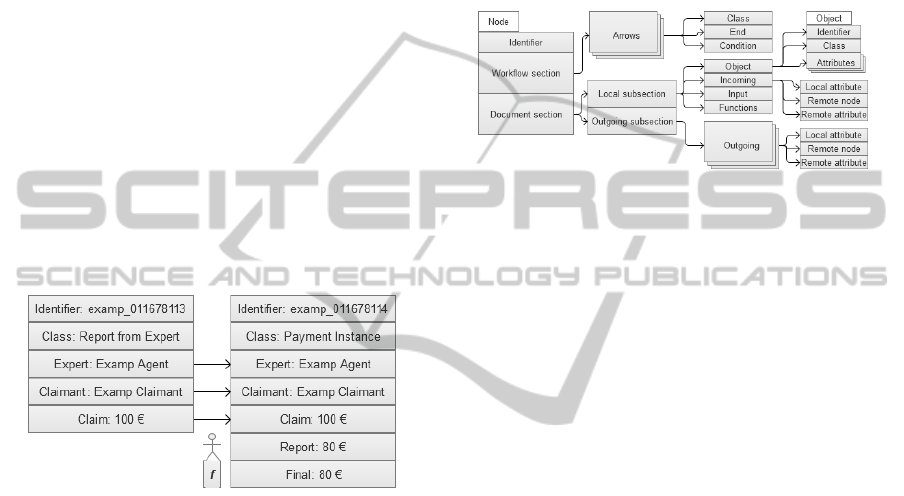
3.4 An Object Oriented Workflow
Model
The basic elements of the new model are nodes.
These nodes are not exactly the same as the nodes de-
scribed above. Let a node be described by three parts:
a unique ID, the workflow section and the document
section.
The workflow section represents the logic of the
business process. This section consists of a list of con-
nections. The representation of the arrows is the same
as described earlier, with respect to the difference be-
tween nodes and ”new” nodes. The arrows represent-
ing transitions are denoted with thick arrows.
The document section of a node can be further di-
vided into two subsections, namely Local and Out-
going. The object of the Local part with the structure
described earlier is created in the node during the exe-
cution of the process, filling the fields through incom-
ing connections, retrieving input data from the user
and evaluating the defined functions.
Figure 4: Process node sections exposed.
The outgoing part of the node’s document section
lists the Outgoing object connections by (local field,
remote node, remote field) triples. It is important to
understand the difference between the workflow ar-
rows that define the workflow control structure and
the connection between object attributes. That is the
reason that different names are givento these two phe-
nomena (arrow, connection) in the model.
4 DATA MODEL,
OBJECT-ORIENTED DATA
STORAGE
In a workflow oriented ERP system a large amount
of objects that belong to different classes has to be
stored in a single database. The number and the type
of attributes can highly vary among different classes.
Storing such inhomogeneous data in a single database
encumbers fast retrieval of data during querying; fast
retrieval is a necessary requirement on any attribute.
Beside the maintenance of the taxonomy, in-
stances of all classes have to be stored and retrieved,
with all the descriptive data of a certain class. Since
the database stores a huge amount of objects, func-
tionality is needed to retrieve not just single objects
but a set of instances based on different filter condi-
tions derived from the attributes.
According to the permanent changes of business
environment and processes, the documents are sub-
jects to change. The queries of the objects created
with the previous, deprecated classes have to be as
fast as the queries for the new objects. Although 30-
60 seconds response time is acceptable for a part of
DesignandImplementationofaWorkflowOrientedERPSystem
163

queries, the majority of them should provide results
in 1-2 seconds response time.
4.1 Document based Storage with
MongoDB
During the development, several different implemen-
tation approaches were studied. Finally three proto-
types were implemented using the MySQL and Mon-
goDB database engines respectively.
In two cases the solution was based on relational
database management systems: in the first case the
”entity-attribute-value” data model’s slightly modi-
fied version was implemented, in the second case
the data were stored in on-the-fly generated data ta-
bles. These two solutions were compared with the
third, document-oriented database solution, which is
a rather natural approach of the problem.
The benchmark environment and results in Figure
5 are presented in details in an article (M´ari´as et al.,
2012). On the figure chart no. 2, 3 and 4 present two
values: the first one indicates the number of classes,
the second shows the average number of attributes in
the database used for the benchmark. The first row
of the figure shows the benchmark results for filter-
ing queries. The diagram no. 1 shows the growing
number of attribute filter options, while digram no. 2
shows the query times for a fixed number of filter op-
tions with growing number of attributes. The charts
in the second row show the average query time of ob-
jects belonging to a certain class, the first with grow-
ing number of classes but fixed average attribute num-
ber, the second with growing number of attributes but
fixed number of classes.
Figure 5: Benchmark test results for different data model
implementations.
Based on the results of the benchmark, the Mon-
goDB based solution was implemented.
5 SOFTWARE ARCHITECTURE
The software system architecture is shown in Fig-
ure 6. The data model is implemented with a com-
bination of relational and schema-less, document-
oriented database systems. Both business processes
and objects are stored in the open-source MongoDB
database system.
The system is available in SaaS (Software as a Ser-
vice) business model. It can be regarded as a web in-
formation system (Moln´ar et al., 2012)(Moln´ar and
Bencz´ur, 2013), as instances are to be installed as
a web application on a web server and the applica-
tion frontend is accessible by the client with a web
browser software. Although the general frontend is
using the standard HTML, CSS and jQuery, the work-
flow editor is written in Adobe Flash. The application
backend is based on PHP, using the CakePHP frame-
work and its MVC implementation.
Figure 6: Basic architecture.
Each company as a tenant has a separate instance
of the system with their own specific data models and
business processes. This separation is obtained by us-
ing virtual private servers.
The system includes an application-server, which
is capable of running multiple threads simultaneously.
This way the structure of the software both from
design and development viewpoints as it is usual
these days breaks down to the following three layers:
database handling, business logic and user interface.
The solutions were extensively tested and piloted
through a commercially not available project called
Amnis with great emphasis on the database imple-
mentation.
5.1 Frontend Components
The system user interface is based on modern web
frontend technologies including HTML5, jQuery and
ICE-B2015-InternationalConferenceone-Business
164

AJAX. The interactive functions can be accessed us-
ing this frontend: general workflow, document and
document type administration. This interface pro-
vides the functionalities to actually run workflow and
submit user data during the interactive steps of the
workflow.
The workflow editor with GUI is one of the most
advanced and spectacular parts of Process Oriented
ERP System. This function is also web-based, us-
ing HTML5 and JavaScript and it makes the creation
and flexible modification of the graphical representa-
tion of the workflowgraph possible. The interface has
zoom and topologically re-order functions.
5.2 Backend Components
The functions of the application server are accessed
from the web user interface through a proxy server
which is implemented in PHP. To actually run the
business processes are performed by the standalone
application server which was developed in the Python
programming language, using Stackless and Twisted
Python frameworks for thread management.
According to the research and benchmarks the in-
homogeneous objects and all business processes of
the system are stored in MongoDB, which is a non-
SQL, document-oriented database system.
6 BUILDING APPLICATIONS
WITH A WORKFLOW BASED
ERP SYSTEM
With the business process modeling tool defined let
us try to describe a real business process. The chosen
process is a system that supports the activities of a
logistical center. The basic states of the system can
be listed as follows:
The trucks get registered in the system by declar-
ing their license plate number and estimated time of
arrival. There is an option to postpone parts of the reg-
istration process. Then, the registered trucks arrive to
the parking area before the given time and wait in a
queue. When the logistical center is ready to receive
them, the trucks enter and the personnel execute the
necessary loading operations. When the operations
are finished, the trucks leave the logistical center.
The states and transitions of the system may be
considered as a relatively simple process. In the fol-
lowing we present and explain the model of the sys-
tem, first by a standard BPML model and then the
alternative workflow model of the process.
6.1 Description of the Process and the
BPML Model
The attributes required to register a truck are Part-
ner, Order number, ETA, Conveyor firm, Quality,
Plate number, Comments, Name of driver and Driver
phone. Every value is given by the user.
As mentioned above, the trucks may choose im-
mediate or postponed registration. The nodes SCH,
EDT refers to the immediate and postponed registra-
tion respectively. The node SCH(EDT) represents the
point where a postponed registration is set to ”ac-
tive”. The attributes of the SCH(EDT) are created
using the incoming values from EDT. Both registra-
tion options lead to the same states and generate the
same type of document (Registration). After the SCH
and SCH(EDT) states there are two possibilities. The
truck either arrives until the given ETA (WPA), or it
does not (SCH error).
If the truck arrives, a document should be created
containing the necessary information to perform the
next step. This information is the Plate number and
the Time of arrival. The Plate number is an incoming
attribute from the object Registration. The Time of
arrival is used to ensure that the queue progresses as
it should, and is filled in by a function of the node.
After the document is created, the truck waits in the
queue.
If the truck does not arrive until the given ETA, an
object must be created containing the necessary infor-
mation to handle the problem. The attributes required
are Partner, Order number, and Driver phone. The
Partner and Order number fields are used to contact
and inform the affected partner regarding the delay.
The Driver phone is used to contact the driver and to
realize a new ETA. All fields are incoming fields from
the object Registration. After the WPA state the doc-
uments of the truck are checked.
If the truck possesses every document regarding
the order (INC) then an object is created to help the
execution of the next step. The object contains the
attributes Plate number and Quality. Plate number is
used as an identifier. Quality is necessary to ensure
that the Partner gets the requested type of cargo. Both
attributes are incoming attributes from the object Reg-
istration.
If the truck does not possess every document re-
garding the order (WPA error) then an object must be
created containing the necessary information to han-
dle the problem. The attributes required are Con-
veyor firm, Order number, Plate number and Missing.
The attributes Conveyor firm, Order number and Plate
number and are used to contact the conveyor firm and
request the missing documents. These are incoming
DesignandImplementationofaWorkflowOrientedERPSystem
165
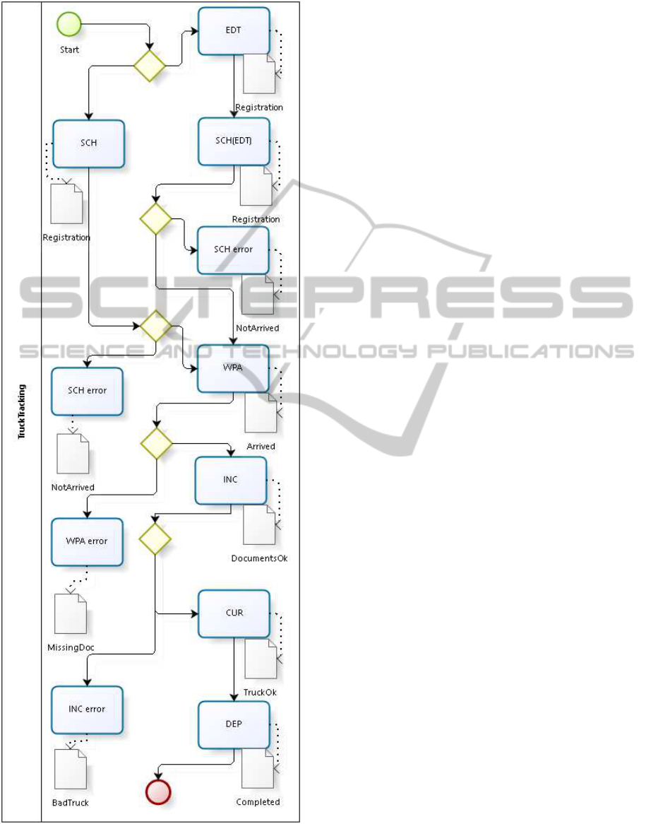
Figure 7: The process for the logistic center software in
BPML model.
attributes from the object Registration. The Missing
field is filled in by a function of the node and stores
the type of the documents missing.
After the INC state, the personnel of the logistical
center execute the necessary loading operations. If
the operations are executed without a problem (CUR)
then an object is created containing the attributes Or-
der number and Completed. The object is kept by the
system as a warrant. The attribute Order number is an
incoming attribute from the object Registration. The
Completed attribute is filled in by the user.
If there is a problem (INC error), like a vehicle that
is inappropriate to transport cargo with the givenqual-
ity, an object must be created containing the necessary
information to handle the problem. The attributes re-
quired are Conveyor firm, Order number and Quality.
All attributes are incoming attributess from the object
Registration, and all are used to request an appropri-
ate vehicle from the conveyor firm.
After the CUR state, the objects are converted into
actual documents (DEP). The documents are given to
the driver and are sent to the conveyor firm. Every
attribute involved (the attributes of the Registration
document) is an incoming attribute from the object
Registration. After the DEP state, the truck leaves the
logistic center.
6.2 The Alternative Workflow Model of
the Process
Figure 8 contains notations that haven’t been men-
tioned previously for the sake of simplicity. The ob-
ject connections with the same end node are the same
color, and different colors were given to the different
logical groups of business process connection. One of
the object connections (purple) links a whole object to
another node.
There is a node where the direction of the arrow is
reversed (default: left to right) (EDT, SCH(EDT)).
7 SUMMARY
The proposed workflow oriented ERP system
methodology satisfies the envisaged objectives:
adaptability and native connection between business
processes and documents. The system is highly
adaptable meaning that any adjustment in the desired
workflow and document related functionalities can be
achieved through a graphical user interface per se.
The connection between business processes and doc-
uments is native meaning that the data flow layer is
built upon the workflow layer: the modification and
ICE-B2015-InternationalConferenceone-Business
166
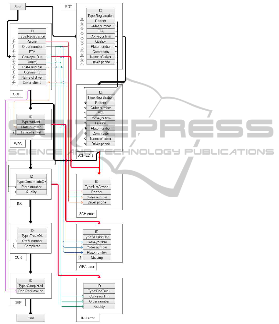
Figure 8: The process for the logistic center software in the
proposed model.
interpretation of previously defined workflows and
data flows are integrated and interconnected.
Several modern and system paradigms appear in
the described system. The biggest challenge was to
solve the database performance problem mentioned
above. After reviewing several database management
systems and their benchmarks, we chose the open
source document based database system MongoDB.
In the future we are going to study the differences
between the proposed system and other systems with
similar capabilities such as TIBCO iProcess Engine,
Microsoft Workflow Manager. We are also plan to
provide a more formal foundation for the whole sys-
tem. We make use the results published in the articles
by one of ours authors (Moln´ar et al., 2012)(Moln´ar
and Bencz´ur, 2013). The document and business pro-
cess model can be treated in a unified framework that
may help the understanding of the functionalities of
the system.
REFERENCES
Aalst, W. V. D. and Hee, K. M. V. (2004). Workflow man-
agement: models, methods, and systems. MIT press,
Cambridge, Mass, USA, 2nd edition.
Becker, J., Rosemann, M., and von Uthmann, C. (2000).
Guidelines of business process modeling. In In Busi-
ness Process Management. Springer (Berlin, Heidel-
berg).
Khan, R. N. (2004). Business Process Management: a prac-
tical guide. Meghan-Kiffer Press, Tampa.
M´ari´as, Z., Nikovits, T., Tak´acs, T., and Giachetta, R.
(2012). A study of large amount of inhomogeneous
data in workflow management systems. In Annales
Univ. Sci. Budapest Sect. Comp. 37 275-292.
Moln´ar, B. and Bencz´ur, A. (2013). Facet of modeling web
information systems from a document-centric view. In
International Journal of Web Portals (IJWP), 5(4), 57-
70.
Moln´ar, B., Bencz´ur, A., and Tarcsi, A. (2012). Formal
approach to a web information system based on story
algebra. In Singidunum Journal of Applied Sciences,
9(2).
DesignandImplementationofaWorkflowOrientedERPSystem
167
