A Vision-based Line Following Strategy for an Autonomous UAV
Alexandre S. Brand
˜
ao
1
, Felipe N. Martins
2
and Higor B. Soneguetti
2
1
Robotics Specialization Group (NERO), Dep. of Electrical Engineering, Federal University of Vic¸osa, Brazil
2
Institute of Engineering, Hanze University of Applied Sciences, Groningen, Netherlands
∗
Keywords:
Unmanned Aerial Vehicles, Nonlinear Control, Vision-based Control, Quadrotor.
Abstract:
Unmanned Aerial Vehicles (UAVs) are versatile machines that can be used in a variety of applications, such as
automatic monitoring of crops and water channels, pest detection, animal counting etc. Autonomous flying is
a desirable feature for UAVs, especially for those that are frequently used in monitoring and inspection of large
areas. In some situations, global positioning system signal is not guaranteed or its error might be too large,
hence other methods of local position feedback are required. In such a context, we present the development of
a vision-based line following strategy for an autonomous UAV. The proposed system is intended to guide an
autonomous UAV to follow water channel margins, crop lines and other similar patterns, to support automatic
monitoring and inspection activities. We present the design of a nonlinear path following controller and we
show that the resulting closed-loop system is stable in the sense of Lyapunov. We also propose a visual-based
line detection algorithm that it is capable of detecting the average position and orientation of the main lines
on the image frames captured by the UAV downwards facing camera. Finally, we present and discuss some
experimental results that show the good performance of the proposed system.
1 INTRODUCTION
According to estimates of the United Nations Food
and Agriculture Organization (FAO), in the next 40
years the world population will reach 8.5 billion peo-
ple. In this scenario, the area available for food pro-
duction tends to be reduced, which means that it is
extremely important to aim the development of sys-
tems to better utilize it. Systems that are focused on
increase productivity of agricultural goods are part of
the so-called precision agriculture. Unmanned Aerial
Vehicles (UAVs) can contribute with the development
of precision agriculture on applications like automatic
monitoring of crops, application of pesticides, pest
detection, among others. One example of such ap-
plication is presented in (Tokekar et al., 2013), that
proposes a system that deals with the problem of co-
ordinated planning for a UAV and a ground mobile
robot to measure the level of nitrogen over a farm in
order to optimize fertilizer application. The authors
argue that the ability to calculate the proper amount
of fertilizer to be applied can dramatically reduce its
use, which is desirable from environmental and eco-
nomic perspectives.
∗
Dr. Martins is on leave from the Federal Institute of
Espirito Santo - Campus Serra - Robotics and Automation
Research Group (NERA), Brazil
Autonomous UAVs commonly rely on Global Po-
sitioning System (GPS) to acquire instantaneous po-
sition information. In a monitoring application, GPS
coordinates might be used as reference way-points for
the UAV to follow. However, the accuracy of GPS
position measurements is influenced by several con-
ditions, such as atmospheric effects, satellite clock er-
rors, receiver electronics etc., which results in a typi-
cal accuracy of about 5 to 15m, on average, for civil-
ian GPS horizontal position fixes (Roebuck, 2012).
In some applications like channel or crop monitoring
on a low altitude flight, such error is too large mean-
ing GPS signals cannot be used as the only source of
information for the UAV controller. Inertial sensors
(like accelerometers and gyroscopes) can also be used
to provide odometry information, but this information
suffers from drifting due to accumulation of measure-
ment errors. Therefore, other methods of local posi-
tion feedback are required for the UAV to accurately
follow the desired path, while GPS fixes could be used
as a general guide towards the correct position.
Several researchers have proposed vision-based
systems to control quadrotors UAVs. For example,
in (Venugopalan et al., 2012) the application of ocean
monitoring is considered. The authors present a con-
trol system for automatic landing of a quadrotor on
an boat using information acquired by a downwards
camera mounted on the UAV. By its turn, in (Warren
314
Brandão A., Martins F. and Soneguetti H..
A Vision-based Line Following Strategy for an Autonomous UAV.
DOI: 10.5220/0005543903140319
In Proceedings of the 12th International Conference on Informatics in Control, Automation and Robotics (ICINCO-2015), pages 314-319
ISBN: 978-989-758-123-6
Copyright
c
2015 SCITEPRESS (Science and Technology Publications, Lda.)

et al., 2015) the authors deal with the problem of long-
range stereo visual odometry for UAVs. They argue
that navigating via vision reduces dependence on GPS
and other global navigation satellite systems, enhanc-
ing navigation robustness in low altitude applications
(< 120m) even in the presence of jamming, spoofing
or long dropouts. Finally, a visual-based control sys-
tem to guide an autonomous aerial vehicle was pre-
sented in (Sotomayor et al., 2014) to be applied on
crop inspection. The orientation of the crop lines for
the UAV to follow is extracted by a computer vision
method based on the oriented textures. The angle ob-
tained by the vision system is the reference for the
PID controllers that guide the UAV. The authors have
presented simulation results to show the viability of
their proposed system.
The system we propose in the present paper fol-
lows the same general idea of the one presented in
(Sotomayor et al., 2014), i.e., the UAV must follow
a line which is oriented according to the main orien-
tation of the lines on the surface. The main orien-
tation of the lines is extracted by a computer vision
algorithm and its angle and position are used as ref-
erence for the UAV path-following controller. The
main differences of our strategy with respect to the
one presented in (Sotomayor et al., 2014) are: (1) in-
stead of using two PID controllers we propose the use
of a nonlinear coupled controller to drive the UAV
throughout the path; (2) we show that the resulting
system is asymptotically stable in the sense of Lya-
punov; (3) we propose a different method to detect
the orientation of the main lines on the image; and (4)
we show experimental results of the line detection al-
gorithm on a real video from a quadrotor downwards
camera while flying outdoors over different surfaces.
Besides its application on precision agriculture, other
possible applications of the proposed system include
carrying instruments to monitor the conditions of wa-
ter channels, rivers, roads, transmission lines, among
others.
2 QUADROTOR MODEL
In this paper we are going to consider the model of
a quadrotor, which is the UAV used during the ex-
periments. A quadrotor is a kind of helicopter that
has four rotors disposed at the ends of a cross-shaped
structure. Two of its rotors rotate in clockwise direc-
tion while the others rotate in counterclockwise direc-
tion. The quadrotor motion is controlled by varying
the speed of each individual rotor. The variation in
speed of each rotor results in turning or tilting that al-
lows the quadrotor to move in any direction in space
or rotate around its own reference system.
The pose of the vehicle in the 3-D space is repre-
sented in generalized coordinates by
e
q =
e
ξ
e
η
T
,
where
e
ξ =
x y z
T
∈R
3
, corresponds to the lon-
gitudinal, lateral and normal displacements in the in-
ertial frame hei, and
s
η =
φ θ ψ
T
∈ R
3
, corre-
sponds to the angles of roll, pitch and yaw with re-
spect to the spatial frame hsi. Notice that hsi has the
same orientation of hei, and thus
s
η ≡
e
η. Fig. 1 il-
lustrates the reference frames and the abstract control
inputs f
1
, f
2
, f
3
and f
4
for a quadrotor.
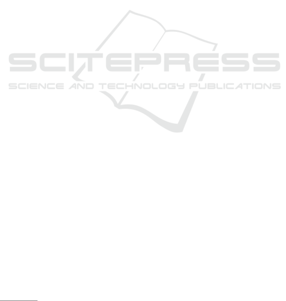
Differently from other works found in the liter-
ature, the motors of the quadrotor shown in Fig. 1
are not aligned with the x− and y− axis of its body
frame. In turn, they are rotated of 45 degrees, which
means that any lateral or longitudinal maneuver re-
quires a joint action of all motors. This is the case of
the AR.Drone quadrotor, which is the UAV we used
in our experiments.
The vector of forces applied in the body frame is
given by
f =
f
x
f
y
f
z
=
0
0
∑
4
i=1
f
i
, (1)
where f
i
is the thrust produced by each motor, which
is proportional to the square of angular velocity, i.e.,
f
i
= C
f
ω
2
. C
f
depends on parametric constants asso-
ciated to the number of rotor blades, width and shape
of the vanes, inner and outer radius of the air flow
by the impeller, air density, among other aerodynamic
constants.
Now, the vector of torques applied in the body
frame is represented as
τ =
τ
φ
τ
θ
τ
ψ
=
k
1
k
1
−k
1
−k
1
−k
1
k
1
k
1
−k
1
k
2
−k
2
k
2
−k
2
f
1
f
2
f
3
f
4
, (2)
where k
1
is the distance between the reference axis
and the point where each force is applied, and k
2
rep-
resents the relationship between the torque generated
by the engine and its corresponding thrust.
Considering a camera attached to the quadrotor
body frame, any roll or pitch maneuver will also ro-
tate the camera frame. As a result, if the UAV is us-
ing its downwards camera information to locate a tar-
get or a line to be followed, the information about its
own orientation needs to be used to compensate for
the image displacement. If the purpose of navigation
is to follow a line in the center of the image plane,
a roll or pitch rotation of the camera frame will be
problematic. For instance, let us consider the line-
following problem. Let us assume that the quadrotor
AVision-basedLineFollowingStrategyforanAutonomousUAV
315
needs to follow a line painted on the ground with con-
stant forward speed. Suppose the vehicle detects its
actual position is to the left of the line, and so its con-
troller generates a command to move it to the right.
For a regular quadrotor to move to the right it needs to
first roll so that the resulting force f has a component
pointing at the y direction. Therefore, the act of trying
to move right (by rolling) will make the line painted
on the ground apparently move even more to the right
on the image captured by the camera. This means that
the apparent error increases even more, which is not
desirable.
In our proposal, the central line in the image plane
is represented by a threshold between sidewalks and
streets, between grass and water channels, or between
planted area and pathways, and so on. Therefore, for
the vision-based line following system to work prop-
erly it is necessary to keep the image frame paral-
lel to the ground frame. This can be accomplished
by mounting the downwards camera on a frame that
compensates for the roll and pitch angles, maintaining
the camera frame aligned with the ground surface.
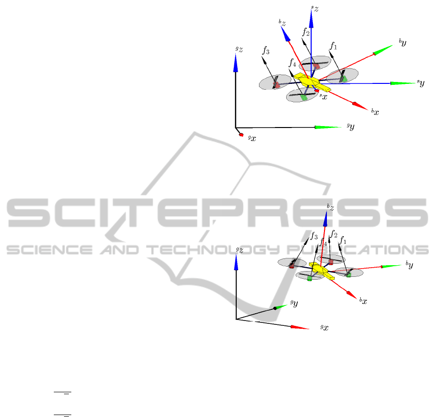
Another way to keep the image frame parallel to
the ground during navigation is to use a holonomic
system, which, in terms of control, is capable to mod-
ify any state variable without affecting any other. For
instance, consider the vehicle shown in Figure 1 and
note that a longitudinal x (or lateral y) displacement
requires a pitch θ (or roll φ) maneuver. Thus the pair
are strongly coupled. Now, compare it with the vehi-
cle shown in Figure 2 and notice that such coupling is
not present. For its motor configuration, the vector of
forces applied in the body frame is given by
f =
sinβ
√
2
(−f
1
+ f
2
+ f
3
− f
4
)
sinβ
√
2
(−f
1
− f
2
+ f
3
+ f
4
)
cosβ
∑
4
i=1
f
i
, (3)
where β is the tilt angle of the motor with respect to
the z− axis of the body frame.
In addition, the vector of torques applied in the
body frame is represented as
τ = cosβ
k
1
k
1
−k
1
−k
1
−k
1
k
1
k
1
−k
1
k
2
−k
2
k
2
−k
2
f
1
f
2
f
3
f
4
, (4)
The tilt angle introduced in this model increases
the maneuverability of the rotorcraft. According to
(Raffo et al., 2011), this makes possible an horizon-
tal displacement without the necessity to employ an
augmented state vector nor cascade control strate-
gies. Therefore, such a vehicle would be suitable for
Figure 1: CAD model of a quadrotor, with the reference
frames and abstract control inputs f
i
associated to them.
The spatial, ground and body frames are denoted by hsi,
hgi and hbi, respectively.
Figure 2: CAD model of a quadrotor with tilted propellers.
our proposed system without the necessity of mount-
ing the downwards camera onto a gimbal stabiliz-
ing frame. However, the augmented maneuverability
comes with an expense of an increase in energy con-
sumption. For example, when the quadrotor is hover-
ing at a fixed position, the horizontal components of
the forces generated by the propellers need to be can-
celled out. Therefore, energy is lost during a hovering
maneuver just to guarantee stationary flight.
In this work we consider only the case of flat sur-
faces and we assume that the inner controller of the
UAV maintains the aircraft in a desired vertical quota.
In this case, for both types of quadrotors the kinematic
model is given by
˙x
˙y
˙
α
=
cosα −sinα 0
sinα cosα 0
0 0 1
u
x
u
y
ω
, (5)
where α is the orientation of the body frame with re-
spect to the ground frame,
˙x ˙y
˙
α
T
is the UAV
velocity vector with respect to the ground frame, and
u
x
u
y
ω
T
is the UAV velocity vector with re-
spect to its body frame. The complete the dynamic
ICINCO2015-12thInternationalConferenceonInformaticsinControl,AutomationandRobotics
316
models of the both types of rotorcrafts are presented
in detail in (Raffo et al., 2010; Brand
˜
ao et al., 2013).
3 LINE FOLLOWING
CONTROLLER
This Section presents the design of the line following
controller for the UAV. Here, we consider that the x
axis of the ground frame is aligned with the line to
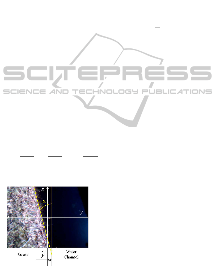
be followed by the aircraft. Figure 3 shows a frame
of a video taken from the UAV downwards camera.
The UAV should follow a path which is parallel to
the line, therefore the orientation error in the image
frame is given by α, while the displacement error is
represented by ˜y. The line to be followed by the UAV
is generated by the line detection algorithm described
in Section 4. Here, such line represents the boundary
between the grass and the water channel.
The control objective is to minimize both the dis-
placement error ˜y and the orientation error α. Thus,
˙
˜y = u
x
sinα + u
y
cosα, and (6)
˙
α = ω. (7)
We are going to show that both ˜y and α are re-
duced by applying the control signals
u
x
= (u
x max
−k
x
|˜y|) cos α, (8)
u
y
= u
ymax
sinα, and (9)
ω = −k
y
˜y
u
x
sinα
α
−u
y
cosα
α
−k
α
α, (10)
where k
x
=
b
1
a
1
+ |˜y|
, k
y
=
b
2
a
2
+ |˜y|
and k
α
=
b
3
a
3
+ |
˜
α|
are designed to avoid saturation of control signals
when |˜y| is large. b
1
, b
2
, b
3
, a
1
, a
2
and a
3
are pos-
itive constants. u
x max
and u
ymax
are the maximum
translational velocities on x and y axis. Notice that
Figure 3: The line following model.
the control signals u
x
, u
y
and ω are directly related to
f
x
, f
y
and τ
ψ
. In closed loop, we have
˙
˜y = [(u
x max
−k
x
|˜y|) + u
ymax
]sinαcosα,
˙
α = −k
y
˜y
u
x
sinα
α
−u
y
cosα
α
−k
α
α. (11)
The stability analysis is given in the sense of Lya-
punov considering the following candidate function
V ( ˜y, α) =
α
2
2
+
Z
˜y
0
k
y
ΓdΓ. (12)
Taking the first time derivative and replacing (11), we
have
˙
V = α
˙
α + k
y
˜y
˙
˜y
= α
−k
y
˜y
u
x
sinα
α
−u
y
cosα
α
−k
α
α
+ k
y
˜y(u
x
sinα + u
y
cosα)
= −k
α
α
2
.
Thus, one can conclude ˜y and α are bounded. Us-
ing La Salle theorem for autonomous systems, taking
into account (11), the greatest invariant set M in the
region
Ω =
˜y
α
:
˙
V ( ˜y, α) = 0
⇒
˜y
α
=
˜y
0
exists only for ˜y = 0. Therefore, the unique invariant
set M is the equilibrium
˜y α
T
=
0 0
T
, which
is asymptotically stable. In other words, ˜y, α → 0 for
t →∞.
The analysis above was made under the assump-
tion of perfect sensing of the line to be followed. But,
when we consider that the line detection system is not
perfect, some displacement error δ
y
and orientation
error δ
α
are added to the closed-loop equations (11).
Using the same Lyapunov candidate it is possible to
show that ˜y and α are bounded, and its bounds depend
on the magnitude of the errors δ
y
and δ
α
.
4 LINE DETECTION
The reference for the UAV controller is generated by
the line detection algorithm. The general idea consists
on smoothing the image, binarizing it and identifying
its main lines. Then, the main orientation is calculated
as an average of the orientation of the main lines, also
considering previous image frames.
A more detailed description is given as follows.
First, a new frame from the video streamed by the
UAV downwards camera is obtained. Then, it is con-
verted to gray-scale and cropped (to cut-off the its
AVision-basedLineFollowingStrategyforanAutonomousUAV
317
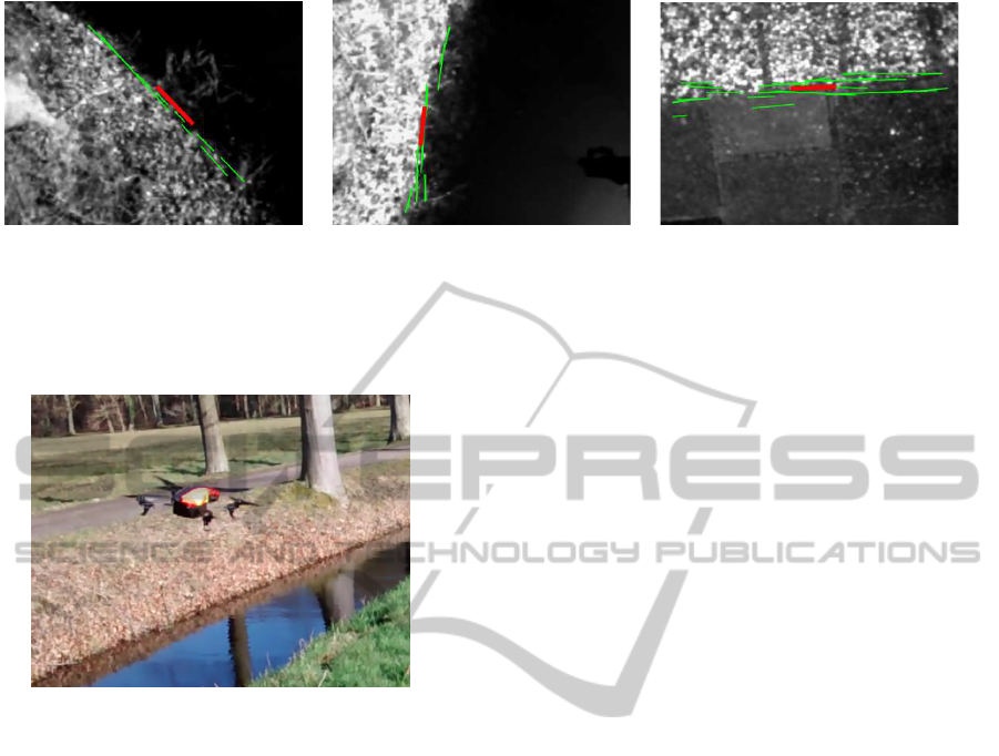
(a) (b) (c)
Figure 5: Examples of the application of the line detection algorithm on different conditions and surfaces: over a water
channel margin (a) and (b), and over different textures of a sidewalk (c). The red line indicates the average position and
orientation of the main lines detected on the previous image frames (shown in green).
Figure 4: Quadrotor used in the experiments.
black margins). The resulting image is filtered via
correlation with a rotationally symmetric Gaussian
low-pass filter of size 84x84 pixels with standard de-
viation of 28. Then, Canny method is applied to the
filtered image to transform it to binary intensity im-
age. A further convolution with the 3x3 horizontal
and vertical Sobel filters is performed to emphasize
borders. Then, because of its robustness to gaps and
noise, standard Hough Transform is applied to the
binary image, and the lines corresponding to the 10
strongest peaks in the Hough transform matrix are ex-
tracted. The orientation of those lines is computed
and classified as belonging to one of four intervals in
the range from 0 to 180 degrees. Only lines belonging
to the interval which has the most lines are considered
for the calculation of the average position and orien-
tation in that frame. Finally, a moving average filter
is used to include the information of the peak lines
from the previous 5 frames on the final average. This
sequence is repeated for every image frame. As a re-
sult, after each frame the position and orientation of
its main lines is obtained, and this information can be
used as a reference for the line following controller.
5 EXPERIMENTAL RESULTS
The quadrotor used in the experiments was the Par-
rot AR.Drone 2.0, shown in Figure 4 during one of
the tests. It has an on-board processor that is respon-
sible for its low-level motor control and body stabi-
lization. Its sensors include a 3 axis gyroscope, a 3
axis accelerometer, a 3 axis magnetometer, a pressure
and a ultrasonic sensors (both pressure and ultrasonic
sensors are used for altitude estimation). Finally, this
UAV has a 60 fps vertical QVGA camera that is used
for ground speed estimation, and a 30 fps horizontal
HD Camera (720p) (Parrot, 2014). Video stream from
either cameras can be obtained via Wi-Fi connection
to be processed on an external computer.
During our experiments we captured the video
streamed by the drone downwards facing camera.
Figures 5 (a) and (b) show the gray-scale frames cap-
tured in two different moments during a flight over
the a water channel margin, and Figure 5 (c) illustrate
the frame captured while flying over a sidewalk. In
all cases, the main lines detected by the proposed al-
gorithm are shown in green, and the average is shown
in red. It can be seen that the proposed algorithm is
capable of detecting the main orientation of the image
pattern, and thus can generate a correct reference for
the line-following controller described in Section 2.
A short video is available at (Martins et al., 2015).
6 DISCUSSION
We have presented a vision-based line detection al-
gorithm and a nonlinear line-following controller for
a UAV. Stability analysis proves that the closed-loop
system formed by the UAV model and the line-
following controller is asymptotically stable in the
sense of Lyapunov. We have also presented a vision-
based strategy to detect the main lines on the images
ICINCO2015-12thInternationalConferenceonInformaticsinControl,AutomationandRobotics
318

captured by the UAV downwards camera. Experimen-
tal results using real video captured by a quadrotor
UAV illustrate that the proposed algorithm is capable
of determining the main position and orientation of
borders such as water channel margins and different
types of ground patterns.
It is important to discuss the limitations of the line
detection algorithm. First, it is assumed that the im-
ages captured by the downwards camera have a pat-
tern which contains a main orientation. Second, the
proposed algorithm relies on contrast variation in or-
der to detect lines. This is not a strong limitation
since contrast variation is common in several situ-
ations, like river and channel margins, streets, etc.
But, surfaces with week contrast variation are likely
to cause the algorithm to perform poorly. Finally, the
presence of shadows also affect the performance of
the algorithm. For instance, during our experiments
we noticed that shadows of tree trunks would have an
important influence when they were visible in the im-
age frame. Because the UAV is moving, we believe
that the influence of shadows can be minimized with
the use a of a more robust filtering method when cal-
culating the average position and orientation of the
main lines.
This work is part of a research that aims to in-
vestigate the use of UAVs in agricultural and rural
areas. As an immediate next step we intend to inte-
grate the line follower controller and the line detec-
tion algorithm for the quadrotor to fly autonomously.
We also plan on integrating the proposed system to
the multi-robot control scheme we have presented
in (Rampinelli et al., 2010; Brand
˜
ao et al., 2010;
Brand
˜
ao et al., 2015) to have the quadrotors flying in
formation, also cooperating with a ground vehicle.
ACKNOWLEDGEMENTS
The authors thank Hanze University of Applied Sci-
ences and the University of Groningen for the support
given to this research. Dr. Brand
˜
ao thanks CNPq and
Funarbe for support his participation in this project.
Dr. Martins also thank Dr. Marco Wiering for his
valuable advices and guidance, CAPES (a foundation
of the Brazilian Ministry of Education) for the finan-
cial support (Project BRANETEC 011/13 and process
BEX 1603/14-0), and the Federal Institute of Espirito
Santo for the authorization to be on leave to work on
his research in the Netherlands.
REFERENCES
Brand
˜
ao, A., Sarapura, J., Caldeira, E., Sarcinelli-Filho, M.,
and Carelli, R. (2010). Decentralized control of a for-
mation involving a miniature helicopter and a team of
ground robots based on artificial vision. In IEEE Latin
American Robotics Symposium (LARS).
Brand
˜
ao, A. S., Rampinelli, V. T. L., Martins, F. N.,
Sarcinelli-Filho, M., and Carelli, R. (2015). The mul-
tilayer control scheme: A strategy to guide n-robots
formations with obstacle avoidance. J Control, Autom
Electr Syst, 26(3):201–214.
Brand
˜
ao, A. S., Sarcinelli-Filho, M., and Carelli, R. (2013).
High-level underactuated nonlinear control for rotor-
craft machines. In IEEE International Conference on
Mechatronics, Vicenza, It
´
alia.
Martins, F. N., Brand
˜
ao, A. S., and Soneguetti, H. B.
(2015). A Vision-based Line Following Strat-
egy for an Autonomous UAV. Available at
http://youtu.be/gd9LFQkHG28.
Parrot (2014). AR.Drone 2.0 Technical Specifications.
Available at http://ardrone2.parrot.com/ardrone-
2/specifications/.
Raffo, G. V., Ortega, M. G., and Rubio, F. R. (2010). An
integral predictive/nonlinear H
∞
control structure for
a quadrotor helicopter. Automatica, 46:29–39.
Raffo, G. V., Ortega, M. G., and Rubio, F. R. (2011).
Nonlinear h-infinity controller for the quad-rotor he-
licopter with input coupling. In Proceedings of the
18th IFAC World Congress, volume 18, pages 13834–
13839.
Rampinelli, V., Brand
˜
ao, A., Sarcinelli-Filho, M., Martins,
F., and Carelli, R. (2010). Embedding obstacle avoid-
ance in the control of a flexible multi-robot formation.
In IEEE Int. Symp. on Industrial Electronics (ISIE),
pages 1846–1851.
Roebuck, K. (2012). Location-Based Services (LBS): High-
impact Strategies-What You Need to Know: Defini-
tions, Adoptions, Impact, Benefits, Maturity, Vendors.
Emereo Publishing.
Sotomayor, J. F., G
´
omez, A. P., and Castillo, A. (2014). Vi-
sual control of an autonomous aerial vehicle for crop
inspection. Revista Polit
´
ecnica, 33(1).
Tokekar, P., Vander Hook, J., Mulla, D., and Isler, V. (2013).
Sensor planning for a symbiotic uav and ugv system
for precision agriculture. Technical Report - Dep.
Comp. Science and Eng., University of Minnesota.
Venugopalan, T., Taher, T., and Barbastathis, G. (2012). Au-
tonomous landing of an unmanned aerial vehicle on an
autonomous marine vehicle. In Oceans, 2012.
Warren, M., Corke, P., and Upcroft, B. (2015). Long-range
stereo visual odometry for extended altitude flight of
unmanned aerial vehicles. The International Journal
of Robotics Research.
AVision-basedLineFollowingStrategyforanAutonomousUAV
319
