
Relative Height Estimation using Omnidirectional Images
and a Global Appearance Approach
Yerai Berenguer, Luis Pay
´
a, Adri
´
an Peidr
´
o and Oscar Reinoso
Departamento de Ingenier
´
ıa de Sistemas y Autom
´
atica, Universidad Miguel Hern
´
andez de Elche,
Avda. de la Universidad s/n. 03202, Elche (Alicante), Spain
Keywords:
Height Estimation, Omnidirectional Images, Radon Transform, Computer Vision.
Abstract:
This work presents a height estimation method that uses visual information. This method is based on the
global appearance of the scenes. Every omnidirectional scene is described with a global appearance descriptor
without any other transformation. This approach is tested with our own image database. This database is
generated synthetically based on two different virtual rooms. One of the advantages of generating the images
synthetically is that noise or occlusions can be added to test the robustness of the algorithms. This database
is formed by a set of omnidirectional images captured from different points of these rooms and at different
heights. With these scenes we build the descriptor of each image and we use our method to estimate the
relative height of the robot. The experimental results show the effectiveness and the robustness of the method.
1 INTRODUCTION
When a mobile robot has to do a task in an unknown
environment, it must carry out two fundamental steps.
On one hand, it must create an internal representation
of the unknown environment (map) and on the other
hand it must be able to estimate its position within
the map. The robot uses the information extracted
from the environment by the different sensors that it is
equipped with. This information is compared with the
data stored in the map to estimate the position of the
robot. There are many kinds of sensors that provide
useful information to the robot, such as touch sensors,
encoders, laser or vision sensors.
Vision sensors have properties that make them
very useful in mobile robotics. These sensors provide
a very rich information from the environment and they
have multiple possible configurations. In this work
we use the omnidirectional configuration. We can find
many previous works that use omnidirectional images
in navigation tasks, such as (Winters et al., 2000).
The classic developments in mobile robotics us-
ing visual sensors, are based on the extraction and de-
scription of some landmarks from the scenes. These
landmarks can be either natural or artificial, such
as SIFT (Scale-Invariant Feature Transform) (Lowe,
1999) and SURF (Speeded-Up Robust Features) (Bay
et al., 2006) descriptors.
More recently some works propose using the
global information of the images to create the de-
scriptors. These techniques have demonstrated to be
a good option to solve the localization and navigation
problems in 2D. (Chang et al., 2010) and (Pay
´
a et al.,
2010) are two examples of this.
Nowadays, the UAVs (Unmanned Aerial Vehi-
cles) are very popular and versatile platforms that can
do several tasks in the field of mobile robotics. Some
researchers have faced previously the problem of lo-
calization with this platform, such as (Mondragon
et al., 2010).
Comparing to previous works, the contribution
of this paper is to extend the use of global descrip-
tors based on omnidirectional images to estimate the
height of the robot. Furthermore we use the omnidi-
rectional images as the vision sensor provides them,
without additional transformations (i.e. we do not
convert them to panoramic images because it would
suppose an additional computational cost, as shown
in (Amor
´
os et al., 2014)). We only build a global-
appearance descriptor for each omnidirectional im-
age based on the Radon transform. The procedure to
obtain this descriptor is summarized in the following
section.
In this research the UAV does not change its in-
clination with respect to the z axis. It will be able
to estimate the relative height between two different
positions along this axis. The Figure 6 shows the sys-
tem scheme that we use in this work, in this scheme
202
Berenguer Y., Payá L., Peidro A. and Reinoso O..
Relative Height Estimation using Omnidirectional Images and a Global Appearance Approach.
DOI: 10.5220/0005512302020209
In Proceedings of the 12th International Conference on Informatics in Control, Automation and Robotics (ICINCO-2015), pages 202-209
ISBN: 978-989-758-123-6
Copyright
c
2015 SCITEPRESS (Science and Technology Publications, Lda.)
we can observe the axes directions, the focus of the
camera (F) and the focus of the mirror (F
0
).
The experiments with our method have been car-
ried out with our own synthetic image database. This
database has been created with two synthetic environ-
ments of two different rooms.
The remainder of this paper is structured as fol-
lows. Section 2 introduces the method we use to de-
scribe global appearance, the Radon transform. Sec-
tion 3 presents the algorithm we have designed for
height estimation. Section 4 describes the image
database used in this research. Section 5 presents the
experiments and results. At last section 6 outlines the
conclusions.
2 GLOBAL-APPEARANCE
DESCRIPTORS:
RADON TRANSFORM
Methods based on the global appearance of the scenes
constitute a robust alternative compared with meth-
ods based on landmark extraction. This is because
global appearance descriptors represent the environ-
ment through high level features that can be inter-
preted and handled easily.
This section presents the image descriptor we have
used to describe the scenes. It is based on global ap-
pearance without any segmentation or local landmark
extraction.
When designing a new description method, we
should take into account several features. This de-
scriptor should have a compression effect in the im-
age information. These should be a correspondence
between the distance of two descriptors and the dis-
tance of the two positions where the images were cap-
tured. The computational cost to calculate and com-
pare them should be low, so that this descriptor can be
used in real time. It should provide robustness against
noise, illumination changes, occlusions and position
changes of the objects in the environment. Further-
more it should have information of the orientation the
robot had when it captured the image. In Section 5 we
will check if these features are met.
We make use of the Radon transform which is de-
scribed in (Radon, 1917). Previous research demon-
strate the efficacy of this descriptor in shape descrip-
tion and segmentation such as (Hoang and Tabbone,
2010) and (Hasegawa and Tabbone, 2011).
The Radon transform in 2D consists of the inte-
gral of a 2D function over straight lines (line-integral
projections).
This transform is invertible. The inverse Radon
transform reconstructs an image from its line-integral
projections.
The Radon transform can be defined as:
R { f (x, y)} = λ
f
(p,φ) =
=
ZZ
+∞
−∞
f (x, y)δ(p −
−→
r
b
−→
p )dxdy (1)
Where f (x,y) is the function to transform. δ is the
Dirac delta function (δ(x) = 1 when x = 0, and δ(x) =
0 elsewhere). The integration line is specified by the
radial vector
−→
p that is defined by
−→
p =
b
−→
p · p where
b
−→
p
is a unitary vector in the direction of
−→
p . p is the
−→
p
module defined by:
p = |
−→
p | (2)
p ≡ αcos φ + βsinφ (3)
The line-integral projections evaluated for each az-
imuth angle, φ, produce a 2D polar function, λ
f
, that
depends on the radial distance p and the azimuth an-
gle φ.
−→
r is a cluster of points which are perpendicular
to
−→
p .
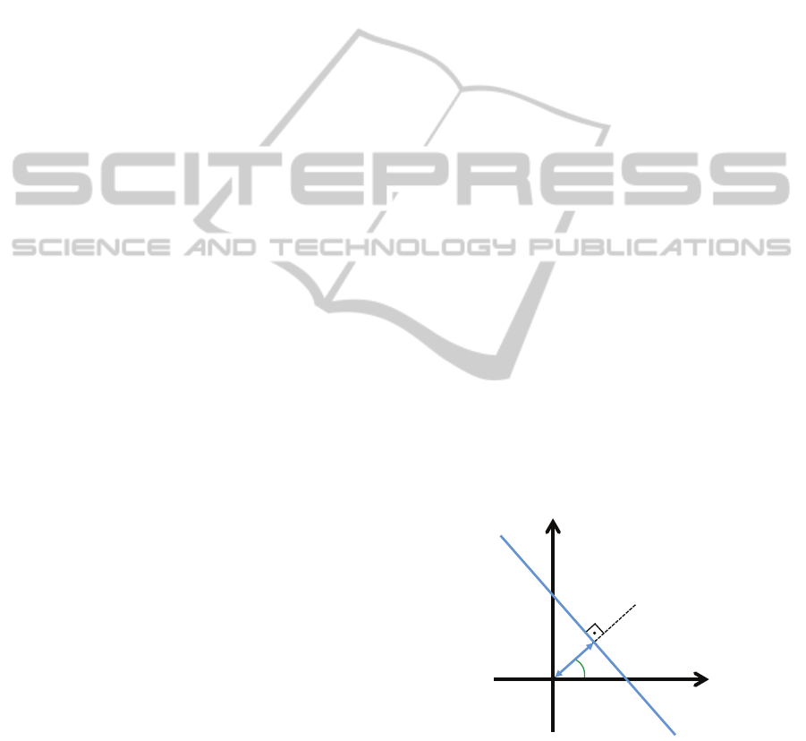
The Radon transform calculation of an image
im(x,y) along the line c
1
(d, φ) (Figure 1) is given by
the following equivalent expression:
R {im(x,y)} =
Z
R
im(x
0
cosφ−y
0
sinφ+y
0
cosφ)ds
(4)
where
x
0
y
0
=
cosφ sinφ
−sinφ cosφ
·
x
y
(5)
!
"
#
$#
%#
&#
'
Figure 1: Line parametrization through the origin distance
d and the angle between the normal line and the x axis, φ.
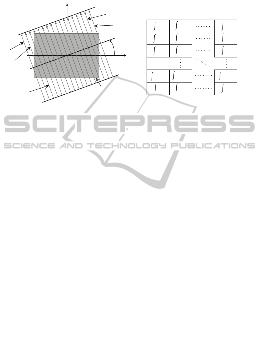
When the Radon transform is applied to images,
it calculates the image projections along the specified
directions through a cluster of line integrals along par-
allel lines in this direction. The distance between the
parallel lines is usually one pixel. The Figure 2(a)
shows the integration paths to calculate the Radon
RelativeHeightEstimationusingOmnidirectionalImagesandaGlobalAppearanceApproach
203
im(x,y)
!"
#"
φ
$
%
"
$
&
"
$
'
"
$
()%
"
$
(
"
(a)
φ=1º
φ=359º
φ=0º
!
!
!
!
!
!
!
!
!
!
!!!
!
!
!
!
!
!
!
!
!
!
!
!
!
!
!!!
!
!
!
!
!
!
!
!
!
!
!
!
!
!
!!!
!
!
!
!
Radon Transform Matrix
(b)
Figure 2: (a) Integration paths to calculate the Radon transform of the image im(x, y) in the φ direction. (b) Radon transform
matrix of the image im(x,y).
transform of an image in the φ direction, and the Fig-
ure 2(b) shows the construction process of the Radon
transform.
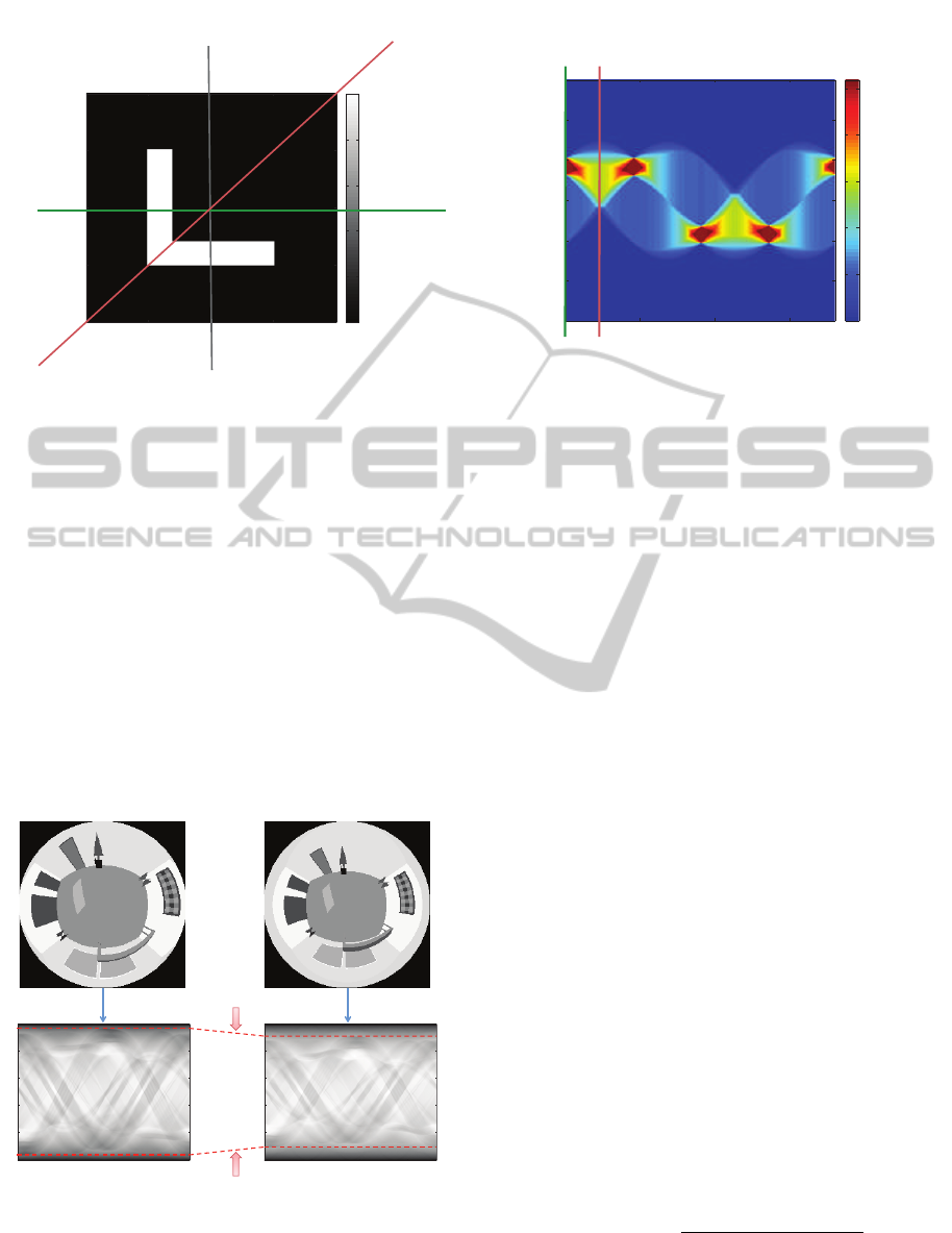
The Figure 3 a sample black and white image, on
the left, and its Radon transform, on the right. Fur-
thermore it shows graphically the process to calculate
the Radon transform.
2.1 Radon Transform Properties
The Radon transform has several properties that make
it useful in localization tasks using images. These
properties are the following:
• Linearity: The Radon transform has the linear-
ity property as the integration operation is a linear
function of the integrand:
R {α f + βg} = αR { f } + βR {g} (6)
• Shift: The Radon transform is a variant operation
to translation. Translation of the two-dimensional
function, by a vector
−→
r
0
= (x
0
,y
0
), has the trans-
lation effect on each projection, this translation is
given by a distance
−→
r · (cos φ,sin φ).
• Rotation: If the image is rotated an angle φ
o
it
implies a shift φ
0
of the Radon transform along
the variable φ. (columns shift).
• Scaling: A scaling of f by a factor b implies a
scaling of the d coordinate and amplitude by a fac-
tor b, and implies a scaling of the Radon transform
by a factor 1/b.
R
n
f
x
b
,
y
b
o
= |b|λ
f
d
b
,φ
(7)
3 HEIGHT ESTIMATION
The Radon transform has been used extensively in
medical imaging applications and in shape descrip-
tion in scenes. However we have not found any pre-
vious application to robot localization and height es-
timation. In this section, we present a method based
on the Radon transform to obtain a topological height
estimator. The method provides information of the
direction and the magnitude of the vertical displace-
ment of the robot using only omnidirectional images
captured by a camera mounted on the robot.
The method compares an image captured at a de-
terminate height with another image captured at an-
other height. As a result, the relative height between
both images must be estimated.
3.1 Compression-expansion of the
Radon Transform
The key of the method resides in the differences be-
tween the Radon transform of two scenes captured al
different heights. If the vertical displacement is up-
wards, then the objects in the omnidirectional scene
tend to move towards the center of the image. This
produces that the information in the columns of the
Radon transform move towards the center row. And
vice-versa, if the displacement is downwards, the in-
formation in the columns moves outwards the center
row. This effect is related to scaling property of the
Radon transform, Equation (7).
This feature produces a characteristic change in
the Radon Transform. When the robot moves up-
wards, the information in the columns of the Radon
ICINCO2015-12thInternationalConferenceonInformaticsinControl,AutomationandRobotics
204
50
1
00
1
50
2
00
50
100
150
200
0
0.2
0.4
0.6
0.8
1
φ=0º
φ=45º
,-&
,-&
.&
,&
(a)
1
!"#$%&'("%)*$(+&
,-&
φ(degrees)
=0º
!
""
#
"" $""
!%%
&'
%(
"
%(
&'
!%%
"
#"
%"
'"
("
!""
φ=0º
φ=45º
(b)
Figure 3: (a) Example image. (b) Radon transform of the example image.
transform tends to move towards the central row
(compression effect), and when the robot moves
downwards, the information in the columns tends to
move outwards the central row (expansion effect).
The method we use to estimate the height of the robot,
is based on these effects.
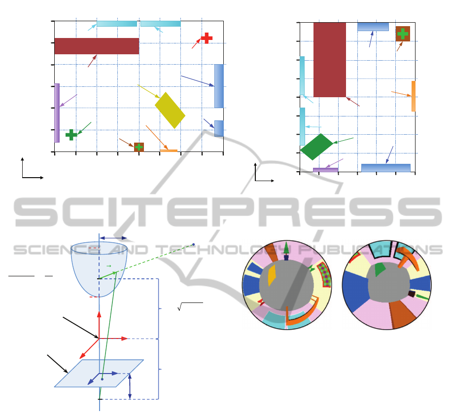
The Figure 4 shows an example of this fea-
ture, two omnidirectional images captured at differ-
ent heights (1m and 1.5m) and their corresponding
Radon transforms. In this figure it is possible to ob-
serve that in the second image the objects have moved
towards the center of the omnidirectional image and
the Radon transform presents a ”compression” effect
with respect the central row.
1
00
2
00 300
50
100
150
200
250
1
00
2
00 300
50
100
150
200
250
!"#$%&'("%)*$(+& !"#$%&'("%)*$(+&
,-./0'&1&2+&
,-./0'&1&234+&
5$+6(-)).$%&78-9'&
Figure 4: Example of the Radon transform compression.
3.2 POC (Phase Only Correlation)
In this subsection we present the method we use to
compare two Radon transforms.
In general, a function in the frequency domain
is defined by its magnitude and its phase. Some-
times, only the magnitude is taken into account and
the phase information is usually discarded. However,
when the magnitude and the phase features are exam-
ined in the Fourier domain, it follows that the phase
features contain also important information because
they reflect the characteristics of patterns in the im-
ages.
Oppenheim and Lim have demonstrated this by re-
constructing images using the full information from
the phase with unit magnitude. This shows that the
images resemble the originals, in contrast to recon-
structing images using the full information from the
magnitude with uniform phase(Oppenheim and Lim,
1981).
POC, proposed in (Kuglin and Hines, 1975), is
an operation made in the frequency domain that pro-
vides a correlation coefficient between two images
(Kobayashi et al., 2004). In our case we compare
two Radon transforms but this does not affect the POC
performance because the Radon transform can be in-
terpreted as an image.
The correspondence between two images im
1
(x,y)
and im
2
(x,y) calculated by POC is given by the fol-
lowing equation:
C(x, y) = F
−1
IM
1
(u,v)·IM
∗
2
(u,v)
|
IM
1
(u,v)·IM
∗
2
(u,v)
|
(8)
Where IM
1
is the Fourier transform of the image
1 and IM
∗
2
is the conjugate of the Fourier transform
RelativeHeightEstimationusingOmnidirectionalImagesandaGlobalAppearanceApproach
205
!"
#!!!"
$!!!"
%!!!"
&%!!!"
&$!!!"
&#!!!"
%!!!" '!!!"$!!!"#!!!"!"&#!!!"&$!!!"&%!!!"&'!!!"
()*+,-""
./01,"
2345)6"#"
2345)6"$"
2,3-5"708,9+"$"
2,3-5"708,9+"#"
:1)*,+"#"
:1)*,+"$"
:/-;,+"
<))-"
=1)6,-;)+"
>"
?"
!"#$%&"'(")*+*
(a)
!"&A!!"&#!!!"&#A!!"
#A!!"
#!!!"
A!!"
#A!!"
$!!!"
#!!!"
A!!"
!"
&A!!"
&#!!!"
&#A!!"
&$!!!"
()*+,-""
./01,"
2345)6"#"
2345)6"$"
;1)*,+"#"
;1)*,+"$"
;/-<,+"
=))-"
>1)6,-<)+"
?"
@"
!"#$%&"'(")*,*
(b)
Figure 5: (a) Plane of the environment 1. (b) Plane of the environment 2. (Dimensions in millimeters).
z
F
F’
c
! ! !
!
! !
!
!
p
P
!
!
! !
!
!
!
!
!
!
!
!
! !!!
y
x
v
u
B
A
Origin
h
r
max
!!
Image plane
Mirror equation:
Figure 6: Scheme of the hyperbolic mirror used to capture
the synthetic omnidirectional images were built.
os the image 2. F
−1
is the inverse Fourier transform
operator.
max{C(x,y)} is a coefficient that takes values in
the interval [0,1] and it measures the similitude be-
tween the two images. This measure is invariant un-
der translations in the original image. To estimate the
similitude between two images we have used the fol-
lowing expression:
dist(im
1
,im
2
) = 1 − max{(C(x,y)} (9)
Furthermore, it is possible to estimate the rela-
tive displacements between the two images ∆
x
and ∆
y
along both axes by:
(∆
x
,∆
y
) = argmax
(x,y)
{C(x,y)} (10)
!"#$%&"'(")*+* !"#$%&"'(")*,*
Figure 7: Example of an omnidirectional image of each En-
vironment.
If we use Radon transforms instead of images, the
value ∆
x
is equal to the relative orientation of the robot
when capturing the two images.
This way, POC is able to compare two images in-
dependently on the orientation and it is also able to
estimate this change in orientation.
3.3 Height Estimation Method
The height estimation method is based on the con-
cepts described in the previous two subsections. It is
invariant to rotation with respect to the z axis thanks
to the use of POC to compare the Radon transforms.
The method works as follows.
The robot takes an omnidirectional image from its
first position and saves its Radon transform. Then the
robot moves upwards or downwards, captures a new
omnidirectional image and saves its Radon transform.
The next step consists in detecting the height dif-
ference between the images. Since it produces a com-
pression effect in the Radon transform with respect to
the central row, our procedure consists in applying a
ICINCO2015-12thInternationalConferenceonInformaticsinControl,AutomationandRobotics
206
! "!!! #!!!
!$%
!$&
!$'
"
()*+,-.//0
! "!!! #!!!
!$%
!$&
!$'
"
()*+,-.//0
! "!!! #!!!
!$#
!
!$#
()*+,-.//0
!"#$%&%'('#)*#+
,-
#)*#./01#h.%213# 4"#$%&%'('#)*#+
,5
#)*#./01#h.%213#
!#6#4#
!"#$ !%#$
!&#$
0 500
1
000
1
500
2
000
0
5
10
15
20
25
30
downwards
upwards
!"#$%&"'(&)%*++,%
-.+/0"11'.2%3#4).0%4#$45$#)"6%
!"#$
Figure 8: Minimum of the vectors (a) V
d1
(case 1) and (b)
V
d2
(case 2). (c) Difference between (a) and (b). (d) a
0
fac-
tor which is proportional to the real relative height between
each image and the test image. This example is in the envi-
ronment 1 with the following position: x = 0 mm and y = 0
mm.
!"
#!!!"
$!!!"
%!!!"
&%!!!"
&$!!!"
&#!!!"
%!!!" '!!!"$!!!"#!!!"!"&#!!!"&$!!!"&%!!!"&'!!!"
("
)"
!"#$%&"'(")*+*
!"#$!!"#%!!!"#%$!!"
%$!!"
%!!!"
$!!"
%$!!"
&!!!"
%!!!"
$!!"
!"
#$!!"
#%!!!"
#%$!!"
#&!!!"
'"
("
!"#$%&"'(")*+*
,&-$.&"-*
Figure 9: Positions of the test images in each Environment.
scale factor a to each column of the first Radon trans-
form and comparing the result with the second Radon
transform using POC. Then, the distance is obtained
using Equation (9). This step is repeated increasing
the compression factor a in each step, until the com-
pression does not make sense, because the transform
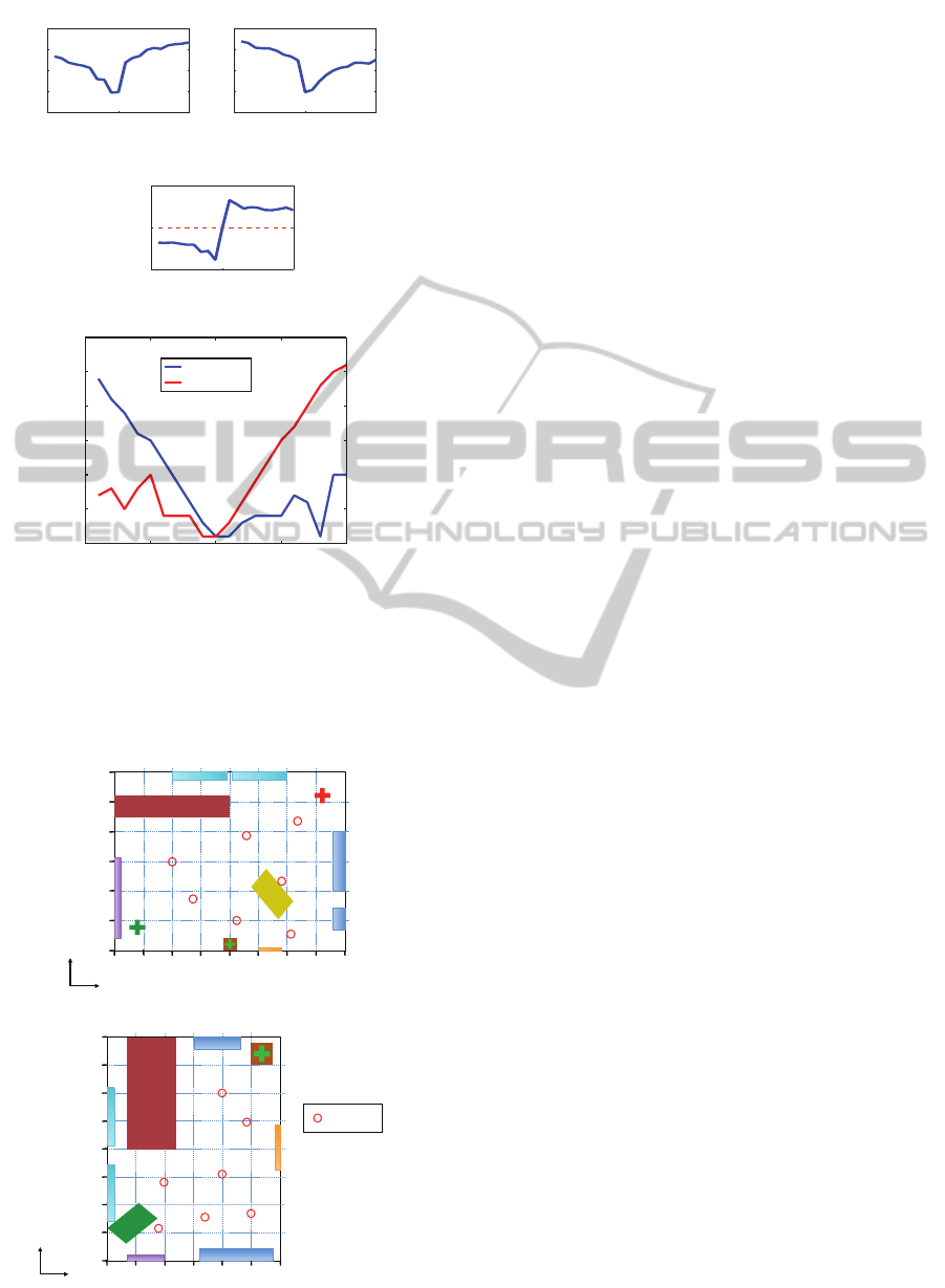
has no relevant information. In this moment the robot
has a vector of distance values V
d
calculated with
POC, each element of the vector corresponds to one
value of the compression factor a. The a factor, that
has produced the minimum of the vector of distances
V
d
, is a magnitude proportional to the relative height,
a
0
.
The problem in this point is that the robot does
not know the translation direction (upwards or down-
wards). If the translation is upwards the second
Radon transform suffers a compression but if the
translation is downwards then the first Radon trans-
form is the one that suffers a compression.
To take this problem into account:
Firstly, the robot compresses gradually the first
Radon transform and carries out the method described
in the foregoing paragraph, to obtain the a
0
factor, but
in this case the robot also has to save the minimum
magnitude d
min
in the vector of distances V
d
. This
case would be the correct one if the robot was moved
upwards
Secondly, the robot repeats the process compress-
ing the second image. This case would be the correct
case if the robot was moved downwards.
Finally, the robot has two factors: a
0
1
from the first
case and a
0
2
from the second case, and it has two d
min
distances: d
min1
and d
min2
. The minimum between
d
min1
and d
min2
determines which is the correct case.
At the end of the process the robot has a magni-
tude a
0
proportional to the vertical displacement and,
depending or the correct case, the displacement has
been upwards (case 1) or downwards (case 2).
4 IMAGE DATABASE
In order to check the performance of the proposed
technique, we have created two virtual environments
which represent two different rooms. In these envi-
ronments it is possible to create an omnidirectional
image from any position. The Figure 5 shows a
scheme of both environments.
The omnidirectional images have 250x250 pixels
and they have been created using the hyperbolic mir-
ror which is described in Figure 6. The parameters
used in the mirror equation are a = 40 and b = 160.
Several images have been captured in both envi-
ronments. In each environment several positions have
RelativeHeightEstimationusingOmnidirectionalImagesandaGlobalAppearanceApproach
207
0 500
1
000
1
500
2
000
0
10
20
30
40
50
60
!"#$%&"'(")*+*
,&'-%(..$&"*/01)&%*02*
31)405*6($76)*8''9*
(a)
0 500
1
000
1
500
2
000
0
5
10
15
20
25
30
35
!"#$%&"'(")*+*
,&'-%(..$&"*/01)&%*02*
31)405*6($76)*8''9*
(b)
0 500
1
000
1
500
2
000
0
10
20
30
40
50
60
!"#$%&"'(")*+*
,&'-%(..$&"*/01)&%*02*
31)405*6($76)*8''9*
(c)
0 500
1
000
1
500
2
000
0
10
20
30
40
50
!"#$%&"'(")*+*
,&'-%(..$&"*/01)&%*02*
31)405*6($76)*8''9*
(d)
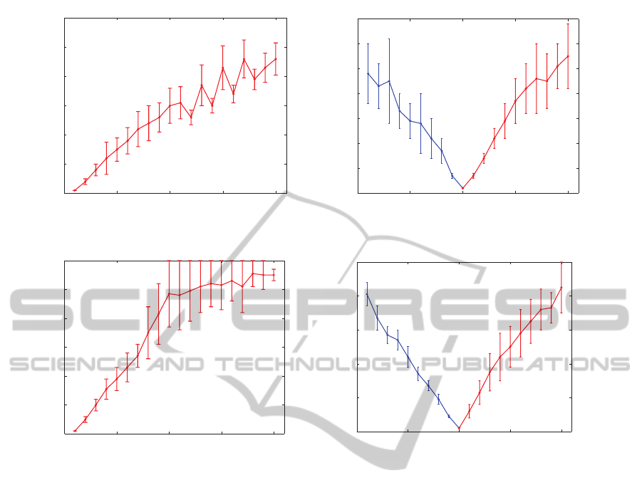
Figure 10: (a) Experiments in the environment 1 with the reference image at height=100 mm. (b) Experiments in the environ-
ment 1 with the reference image at 1000 mm. (c) Experiments in the environment 2 with the reference image at 100 mm. (d)
Experiments in the environment 2 with the reference image at 1000 mm.
been chosen on the floor and a set of images above
these positions were captured to carry out the experi-
ments. The minimum height is 100 mm, and the max-
imum 2000 mm, with a step of 100 mm. In the Fig-
ure 4 there is an example of two different images at
different heights. And the Figure 7 shows one omni-
directional image of each environment.
5 EXPERIMENTS AND RESULTS
In this section the results of the experiments with
our height estimation method are shown. As ex-
posed in section 3, one of the necessary steps is
to differentiate the direction of the translation (up-
wards or downwards). To distinguish this, it is nec-
essary to calculate the difference between both val-
ues: min(V
d1
)−min(V
d2
). This difference determines
which minimum is the lowest and it determines which
is the correct direction (upwards or downwards). The
Figure 8 shows an example of this. In this figure we
take the image captured at 1000 mm as reference. The
Figure 8(a) and the Figure 8(b) show the minimum of
the vectors V
d1
(case 1) and V
d2
(case 2). The Figure
8(c) shows the difference between both vectors. If
the difference is negative, the correct case is the case
1 and if the difference is positive, the correct case is
the case 2. In Figure 8(d) the a
0
factor is represented
for each height in both cases (case 1: downwards and
case 2: upwards). This factor is proportional to the
real relative height between each image and the ref-
erence image. As we can observe in Figure 8(c), the
correct case for heights lower than 1000 mm is the
case 1 (downwards) and for heights higher than 1000
mm is the case 2 (upwards). This determines that in
Figure 8(d) the blue line to the left of 1000 mm indi-
cates the translation magnitude downwards the refer-
ence image and the red line to the right of 1000 mm
indicates the translation magnitude upwards the ref-
erence image. We can observe that the functions are
quite linear.
The Figure 8 is a specific example to show the
ICINCO2015-12thInternationalConferenceonInformaticsinControl,AutomationandRobotics
208

method steps. To demonstrate the correct perfor-
mance of our method we have done a whole set of
experiments in both virtual environments at different
positions. The Figure 9 shows the positions where the
images were captured in each environment to carry
out the experiments. We use a total of 14 positions
with 20 images in each position.
In the Figure 10, the results of these experiments
can be observed. The red line shows the magnitude of
translation upwards and the blue line shows the mag-
nitude of translation downwards. We can observe that
these experiments demonstrate that the method is very
linear for values of relative height around 1 meter.
6 CONCLUSIONS
In this work a method to estimate the height of the
robot has been presented. This method uses omnidi-
rectional images and transforms them with the Radon
transform to make the descriptors of each image. Fur-
thermore it compares the descriptors and finally es-
timates the relative height of the robot. Taking into
account the changes that Radon transforms of scenes
suffer when the robot changes its height.
The experiments included in this paper use our
own image database created synthetically from two
different environments. The results demonstrate that
the method is able to estimate the relative height be-
tween two images with robustness and linearity.
The method is invariant to rotation with respect to
the floor plane because the POC comparison is invari-
ant to shifts of the Radon transform.
The results of this work encourage us to continue
this research line. It will be interesting to do the
experiments with real images and also with images
which have noise, occlusions or changes in lighting
conditions. Furthermore we think that the study of
movements in 6 degrees of freedom will be interest-
ing to investigate.
ACKNOWLEDGEMENTS
This work has been supported by the Spanish govern-
ment through the project DPI2013-41557-P.
REFERENCES
Amor
´
os, F., Pay
´
a, L., Reinoso, O., and Valiente, D. (2014).
Towards relative altitude estimation in topological
navigation tasks using the global appearance of visual
information. VISAPP 2014, International Conference
on Computer Vision Theory and Applications, 1:194–
201.
Bay, H., Tuytelaars, T., and Gool, L. (2006). Surf: Speeded
up robust features. Computer Vision at ECCV 2006,
3951:404–417.
Chang, C., Siagian, C., and Itti, L. (2010). Mobile
robot vision navigation and localization using gist and
saliency. IROS 2010, Int. Con on Intelligent Robots
and Systems, pages 4147–4154.
Hasegawa, M. and Tabbone, S. (2011). A shape descrip-
tor combining logarithmic-scale histogram of radon
transform and phase-only correlation function. In
Document Analysis and Recognition (ICDAR), 2011
International Conference on, pages 182–186.
Hoang, T. and Tabbone, S. (2010). A geometric invari-
ant shape descriptor based on the radon, fourier, and
mellin transforms. In Pattern Recognition (ICPR),
2010 20th International Conference on, pages 2085–
2088.
Kobayashi, K., Aoki, T., Ito, K., Nakajima, H., and Higuchi,
T. (2004). A fingerprint matching algorithm us-
ing phase-only correlation. IEICE Transactions on
Funda- mentals of Electronics, Communications and
Computer Sciences, pages 682–691.
Kuglin, C. and Hines, D. (1975). The phase correlation
image alignment method. In Proceedings of the IEEE,
International Conference on Cybernetics and Society,
pages 163–165.
Lowe, D. (1999). Object recognition from local scale-
invariant features. ICCV 1999, Int. Con. on Computer
Vision, 2:1150–1157.
Mondragon, I., Olivares-M
´
ended, M., Campoy, P.,
Mart
´
ınez, C., and Mejias, L. (2010). Unmanned aerial
vehicles uavs attitude, height, motion estimation and
control using visual systems. Autonomous Robots,
29:17–34.
Oppenheim, A. and Lim, J. (1981). The importance of
phase in signals. Proceedings of the IEEE, 69(5):529–
541.
Pay
´
a, L., Fern
´
andez, L., Gil, L., and Reinoso, O. (2010).
Map building and monte carlo localization using
global appearance of omnidirectional images. Sen-
sors, 10(12):11468–11497.
Radon, J. (1917). Uber die bestimmung von funktio-
nen durch ihre integralwerte langs gewisser mannig-
faltigkeiten. Berichte Sachsische Akademie der Wis-
senschaften, 69(1):262–277.
Winters, N., Gaspar, J., Lacey, G., and Santos-Victor, J.
(2000). Omni-directional vision for robot navigation.
IEEE Workshop on Omnidirectional Vision, pages 21–
28.
RelativeHeightEstimationusingOmnidirectionalImagesandaGlobalAppearanceApproach
209
