
Multi-granularity Modeling of Variable Structured Rocket
based on Declarative Language
Wanmeng Zhou, Hua Wang, Fuyu Sun and Haiyang Li
College of Aerospace and Engineering, National University of Defense Technology, DeYa Street, Changsha, China
Keywords: Modelica, Object-orientation, Declarative Modeling, Variable Structured Rocket, Rocket Simulation
Library, Multi-granularity.
Abstract: The development of the rocket design process depends heavily on the effective and accurate modeling
method. This paper elaborates the procedure to establish the variable structured rocket simulation package
with the declarative modeling language Modelica. The package includes the rocket library with basic rocket
components and rocket products with subsystems and segments. Some of the components like body and
measurement take full advantages of the Modelica object-oriented characters, while others like control
system and aerodynamics are assembled on the basis of traditional flight dynamics. The multi-granularity
library for variable-structured rocket is verified with a case study. The results indicate that the library is
successfully applied to the rocket modeling for flight control system design and is capable of rocket design
in different phases.
1 INTRODUCTION
The object-oriented modeling language, Modelica, is
widely used in large scaled multi-domains
simulation. Hilding Elmqvist (1992) proposed its
main opinion firstly, which developed along with
Differential Algebraic Equations (DAE). Modelica
is now mostly used in mechanics design (Ferretti
and Vigan, 2005) and aviation (Moormann and
Looye, 2002) areas, but few researches can be seen
in rocket flight simulation.
Object-orientation and non-causality are the
main advantages of Modelica over other modeling
languages (Alejandro and Perez, 2001). In
consideration of two advantages above,Modelica
models established through declarative modeling
method, which is the process constructing the
system out of assemblies in the way same as the
topological structure, can always embody the multi-
granularity of the physical system. Connectors and
assemblies in the Modelica library can accomplish
the declarative modeling, which reflect physical
connection logics and similar hierarchical structure
with the practical system.
Nowadays, researches about Modelica in rocket
modeling areas still concerned about the flow
direction and the corresponded libraries are
constructed under the subjects other than objects
(Zhang et al., 2010), which conceal the superiority
over traditional methods and lower the utilization of
the standard Modelica library. Some of the
researches used the six degree of freedoms model
(Gertjan, 2008) which took few advantages of multi-
body dynamics library (Schiavo et al., 2006; Zhang
et al., 2011), others established specific defined
environment functions (Tiziano and Marco, 2005) to
calculate the gravity and atmosphere parameters.
Moreover, most flight vehicle is concerned about the
fixed structure with the same amount of variables,
yet the variables in multi-stage rockets composed of
segments are changed due to separations. It has
become a new challenge for multi-body fight vehicle
modeling.
For taking full advantages of non-causality and
object-orientation characters, this paper proposes the
Modelica modeling method in variable structured
rocket and aims for establishing a multi-granularity
rocket simulation library. Rocket modeling is a
progress to build the rocket library as Figure 1. In
order to decrease the complexity of the rocket
modeling and enhance the universality, the rocket
library and products are encapsulated in one package
named ‘RocketSim’. The simulation results of
variable-structured rocket during the powered phase
will be presented and discussed finally in the end.
344
Zhou W., Wang H., Sun F. and Li H..
Multi-granularity Modeling of Variable Structured Rocket based on Declarative Language.
DOI: 10.5220/0005507703440351
In Proceedings of the 5th International Conference on Simulation and Modeling Methodologies, Technologies and Applications (SIMULTECH-2015),
pages 344-351
ISBN: 978-989-758-120-5
Copyright
c
2015 SCITEPRESS (Science and Technology Publications, Lda.)
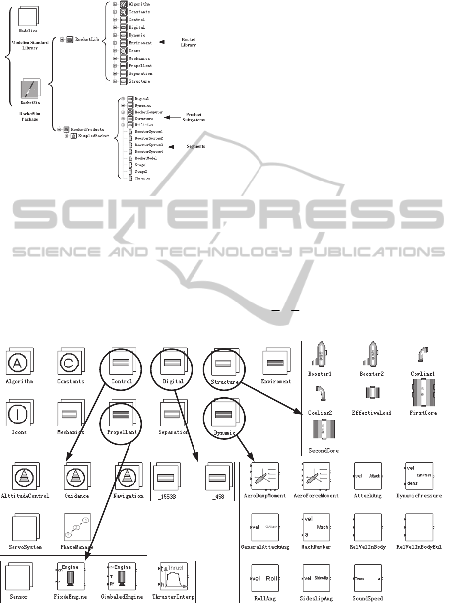
Figure 1: Level structure of the RocketSim package.
2 MULTI-GRANULARITY
ROCKET LIBRARY
Rocket library includes: control system, dynamic
system, mechanics, propellant, separation, digital,
environment, algorithm, constants and icons, shown
as Figure 2. Algorithm, constants and icons are
assistant resources. Control system and digital
package belong to electronics. Mechanics package,
structure, separation and dynamics belong to
mechanics. Propellant belongs to thermotics.
Control system is composed of GNC packages,
phase management block and servo systems. Digital
package includes 458 and 1553B buses. Propellant
includes the sensor in the tank, thrusters
interpolating block and engines. Dynamics mainly
contains all the components associated with the
aerodynamics computation. Structure contains the
main structure parts in rockets. Environment,
separation and mechanics are explained in details in
the following sections.
2.1 Environment Package Design
Original world model cannot provide J2 point
gravity model and the atmosphere parameters, so it
should be modified to gain more accurate
environment. The gravity model considering J2 is
expressed as
re
mg mg
00
e
Gr ω
(1)
where
r
g
and
g
e
are
22
2
2
22
2
2
2
1()(15sin)
,sin()
2()sin
e
r
y
e
e
a
gJ
r
rr
r
a
gJ
rr
(2)
Figure 2: RocketLib components.
Multi-granularityModelingofVariableStructuredRocketbasedonDeclarativeLanguage
345
Models described above are applied in the world
model and the J2 point gravity is defined as a new
gravity type in the type class.
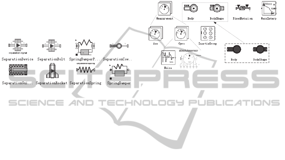
2.2 Separation Package
Separation devices shown in Figure 3 are the critical
assemblies in variable structured multi-body
dynamics; they can be classified according to the
constraints modes. Separation package contains
several common devices like separation bolts,
separation guide rail and separation rocket, etc.
Figure 3: Mechanics package components.
The separation process is accomplished by switching
constrained equations in mechanic frames. Due to
the solving mechanism, the number of variables
must be equal to that of equations, which means the
quantity of equations in each judgment branch
should be the same. Modelica codes are listed as:
r_rel = frame_b.r_0 - frame_a.r_0;
v_rel = der(r_rel);
angle = Frames.axesRotationsAngles(
Frames.relativeRotation(
frame_a.R,frame_b.R),{1,2,3}
);
w_rel = Frames.angularVelocity1(
Frames.relativeRotation(
frame_a.R,frame_b.R));
if separationsignal ==
SeparationSignal then
zeros(3) = frame_b.f;
zeros(3) = frame_b.t;
else
zeros(3) = der(v_rel);
zeros(3) = der(w_rel);
end if;
zeros(3) = frame_a.f +
Frames.resolveRelative(
frame_b.f, frame_b.R,
frame_a.R);
zeros(3) = frame_a.t +
Frames.resolveRelative(
frame_b.t, frame_b.R,
frame_a.R) + cross(
Frames.resolve2(frame_a.R, r_rel),
Frames.resolveRelative(frame_b.f,
frame_b.R, frame_a.R));
2.3 Mechanics Package
Mechanics library shown as Figure 4 is the directive
manifestation of non-causality in rocket modeling.
Mechanics package includes measurements, body,
body shape, fixed rotation and mass interpolating
block.
Figure 4: Mechanics package components.
All the mechanics components convey the physical
quantities through the frames of the connectors. The
body and body shape are derived from original body
and body shape, whose centre of mass, inertia and
mass become the input variables. Measurement is
the package including accelerometer and gyroscope,
which are the absolute sensors assembled with the
measurement noise generator. The random seed and
uniform distribution random generation functions
are acquired by loading the external C functions
through the head file “STDLIB.H” in the specified
path.
3 ROCKET PRODUCT
ASSEMBLING
3.1 Rocket Modeling and Simulation
Flow
Before the whole rocket product is assembled, some
of the segments and subsystems are required to be
constructed from components in the rocket library
and Modelica standard library. When the whole
product is completed, the bottom platform will
automatically determine the equations and values of
the source codes. Then, the code generator will sort
and trim the equations and translate the Modelica
codes into executable codes. The flow from
assembling to simulation is shown in Figure 5.
Most segments can be assembled directly with
the rocket library, but aerodynamics and rocket
computer still need further packaging. The details
are elaborated below.
SIMULTECH2015-5thInternationalConferenceonSimulationandModelingMethodologies,Technologiesand
Applications
346
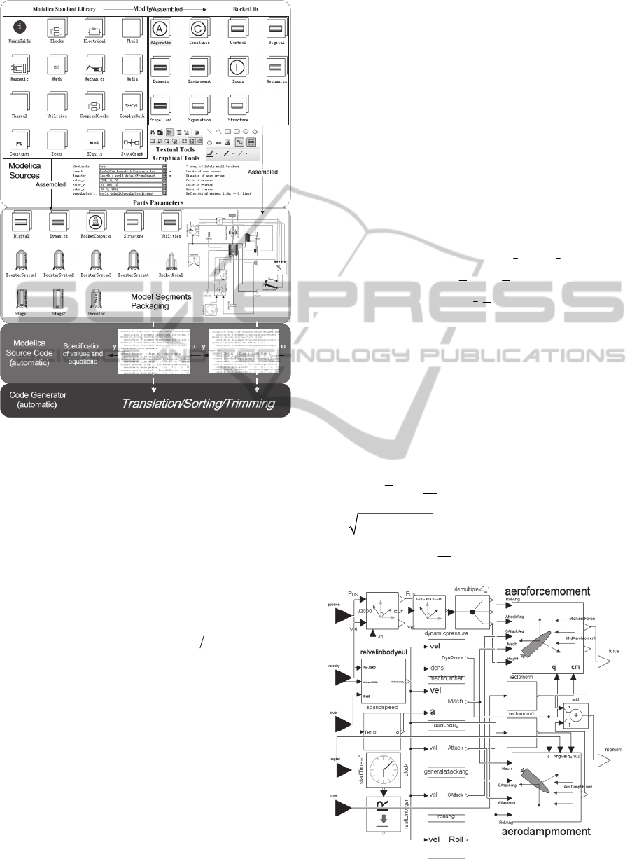
Figure 5: Modeling and simulation flow.
3.2 Main Subsystems Affirmation
3.2.1 Aerodynamics Subsystem
Aerodynamics force resolved in the body coordinate
is
x
x
yy
z
z
RC
RqSC
RC
b
R
(3)
where dynamic pressure
2
2qv
,
is the
atmospheric density,
S
is the characterized area,
and
x
C
,
y
C
,
z
C
are the air resistance coefficient,
elevating force coefficient and lateral force
coefficient. The coefficients are expressed as
22
z
y
xxox x
yyoy yz
zz zy
CC C C
CC C C
CC C
(4)
where
x
o
C
,
2
x
C
and
2
x
C
are resistance coefficients
from unsymmetrical structure, unit attack angle and
slide angle;
yo
C
,
y
C
and
z
y
C
are elevating
coefficients from unsymmetrical structure, unit
attack angle and angle of rudder reflection;
z
C
and
y
z
C
are lateral force coefficients from unit slide
angle and angle of rudder reflection;
x
,
y
and
z
are actual angle of rudder reflection.
Aerodynamic moment resolved in body
coordinate is
bx x
by y
bz z
M
m
M
qSL m
M
m
b
M
(5)
where
L
is rocket characterized length;
x
m
,
y
m
and
z
m
are moment coefficients, expressed as
yyx
x
yy x
z
z
xy
xxox xxxyx x
yx
yy yyy y
z
zzoz zzz
mm m m m m m
mm m m m
mm m m m
(6)
where
x
o
m
and
zo
m
are coefficients caused by
production errors;
x
m
and
y
m
are coefficients
caused by unit slide angle;
z
m
is the moment
coefficient from unit angle of attack;
y
x
m
,
x
x
m
,
y
y
m
and
z
z
m
are resistance coefficients from
angle of velocity; the uniform unit angle of
velocities
(,,)
2
i
i
L
ixyz
v
, where the velocity
222
x
yz
vvvv
. Angle of attack and slide are
given by
arctan
y
x
v
v
,
arctan
z
x
v
v
.
Figure 6: Aerodynamics block.
Multi-granularityModelingofVariableStructuredRocketbasedonDeclarativeLanguage
347
According to Eq. (3) to Eq. (6), the
aerodynamics model is established in Figure 6,
where the general angle of attack is the equivalent of
the slide angle, and the coefficients above are
obtained by interpolating.
3.2.2 Rocket Computer
Rocket computer is composed of phase management
block, guidance and control blocks in first phase and
second phase. The input signal of the phase switch
function is obtained from digital buses, which
include the measurements from inertia groups in first
stage and second stage. The virtual function is
designed to choose the correct signals for guidance
and control blocks. The control signals are then
chosen by the phase switch block.
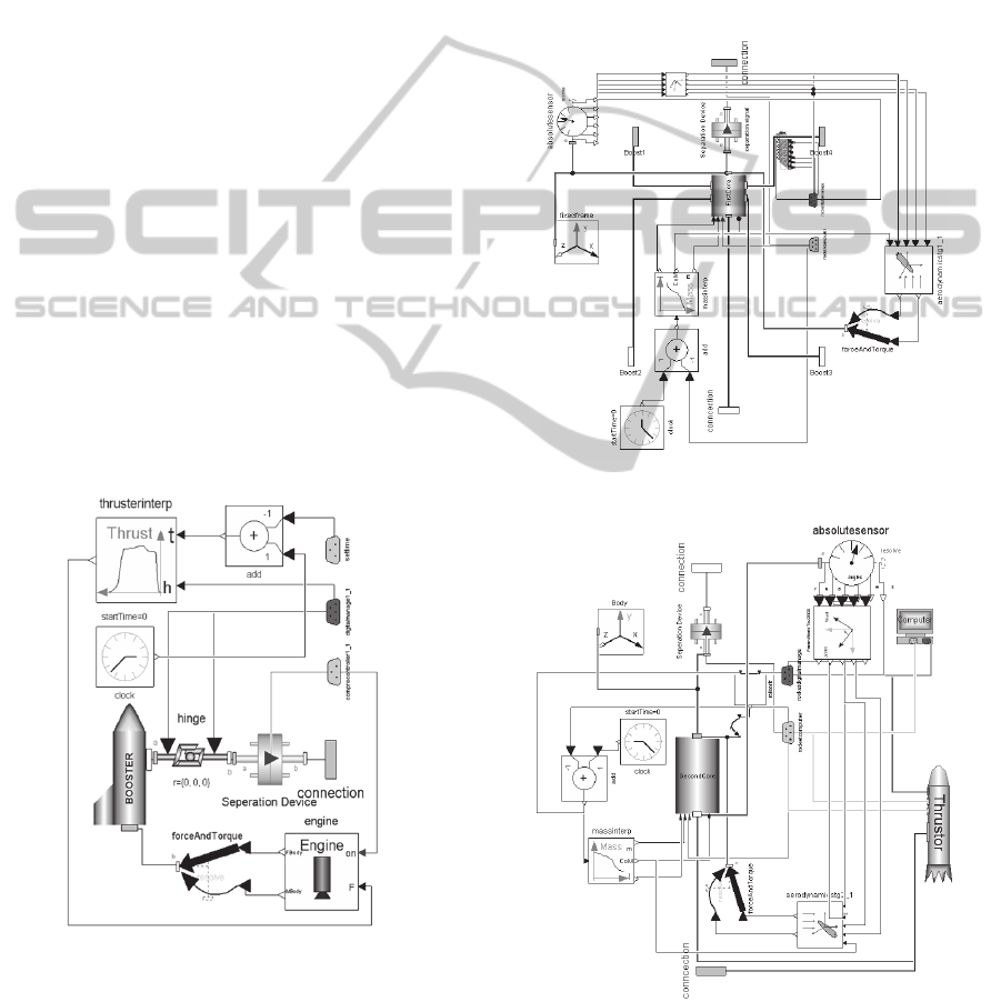
3.3 Rocket Segment Packaging
3.3.1 Booster Segment System
Inner structure and outer ports of booster model is
shown as Figure 7. The values interpolated from the
experimental data are utilized to replace the real
working procedure. The swaying signals and the
rocket height are obtained from bus 458, while the
signal of starting up and separation is conveyed
through 1553B.
Figure 7: Booster system.
3.3.2 Systems in the First and Second Cores
The mass and inertia of the rocket are focus in the
core segments and mainly depend on the two
interpolation blocks. When the first stage separation
signal in 1553B is changed into high level and the
thrusters in the second core start up, the interpolating
blocks in second stage begin to work and the rocket
computer begins to receive the measurements from
the second inertia group. The control signals are
transmitted from the computer rocket to first stage
system through the bus and transformed into the
boosters’ swaying angles by the synthetic controller.
Furthermore, the outer equivalent aerodynamics is
applied on first and second stages. The inner
structures of two-stage systems are shown as Figure
8 and Figure 9.
Figure 8: Inner structure in the first core.
Figure 9: Inner structure in the second core.
3.3.3 Rocket Product
The rocket product is established of seven segments
SIMULTECH2015-5thInternationalConferenceonSimulationandModelingMethodologies,Technologiesand
Applications
348
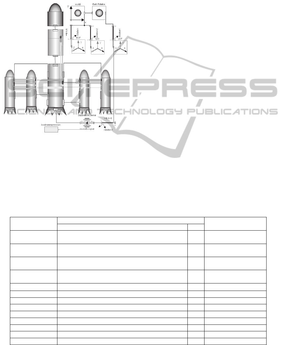
including a first stage, a second stage, an effective
load and four boosters. The segments’ physical
structures are connected with mechanics connectors
and the data transmitting is carried through 1553B
and 458 digital buses. The whole structure of the
rocket product is shown in Figure 10.
Figure 10: Top-level of simplified two-stage rocket.
4 SIMULATION RESULTS AND
ANALYSIS
A case study about two-stage rocket flight
simulation in powered phase is described in this
section. The parameters setting blocks including
rocket computer, body and interpolating blocks
about the mass, aerodynamics and thrusters. The
thrusters interpolating block and rocket computer of
the rocket model are setting as Table 1.
Most animation choices are set as false, causing
the quantities of variable decrease from 14000 to
9420, thus enhance the effectiveness of the
simulation. Choose flight states at 30s,60s,90s,
120s as the characterized points. The standard and
calculated ballistic parameters in the specific points
are listed as below.
The rocket motion states and mass history in
powered phase are shown in Figure 11 to Figure 14.
The first stage of the flight adapts exhausted cut
off, the shutdown signal emerges when fuel level of
tank under certain height at 62.73s. The second stage
takes the perturbing guidance law, calculating the
characterized shutting time accordance with the
standard time 120.043s. The parameters of the
shutdown point are
146099m
k
x
,
117480m
k
y
,
27577.1m
k
z
;
2916.32m/s
xk
v
,
1905.97m/s
yk
v
,
216.970m/s
zk
v
. Compared with the standard
parameters, one can conclude that the rocket model
satisfies the rocket requirement of precisions. Rocket
positions and velocities are continuously changing
along with the time. The states in x and y tunnels
alter more rapidly, but the position in z tunnel
changes smoothly and the velocity remains around
230 m/s. It means the rocket flight is inside the
launch plane. The nonzero values of initial velocity
are due to the earth rotation relative to the launch
inertial reference.
Table 1: Initial properties setting.
Name
Parameters
Parts
Value Unit
fileName
" /Work/RocketSim/RocketProducts
/SimpledRocket/Resources/Data/Stg1Thrust.dat"
—
booster.thrusterinterp
fileName
" /Work/RocketSim/RocketProducts
/SimpledRocket/Resources/Data/FirstCoreMass.dat"
—
firstcore.massinterp
fileName
" /Work/RocketSim/RocketProducts
/SimpledRocket/Resources/Data/SecondCoreMass.dat"
—
secondcore.massinterp
fileName
" /Work/RocketSim/RocketProducts/
SimpledRocket/Resources/Data/AeroDynData.txt"
—
aerodynamic
iniDate {2008, 6, 1, 12, 0, 0}
—
computer
launchAzi 53.292170909143 deg computer
launchLLA {30,120, 0} deg computer
time_stage1_start 0 s computer
time_stage1_shut 63.1 s computer
time_stage1_sep 64.1 s computer
time_stage2_start 65 s computer
time_stage2_shut 132 s computer
time_stage2_sep 133 s computer
Multi-granularityModelingofVariableStructuredRocketbasedonDeclarativeLanguage
349
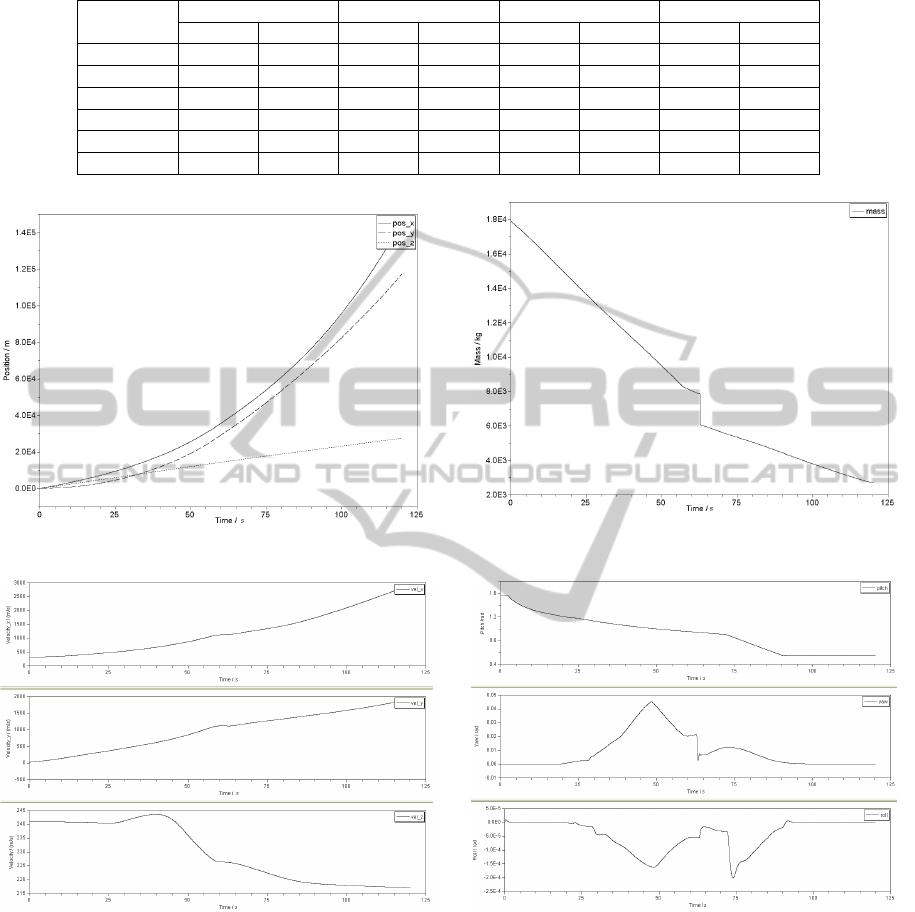
Table 2: Characterized points’ simulation and standard results.
Parameters 30s 60s 90s 120s
Sim Std Sim Std Sim Std Sim Std
X/m 12006.3 12008.7 35723.7 35718.8 76774.5 76761.2 145983 145972
Y/m 6668.08 6672.61 29276.9 29288.6 67396.1 67416.0 117404 117431
Z/m 7222.06 7223.91 14362.6 14363.7 21037.0 21023.2 27568.5 27554.9
Vx/(m/s) 535.235 535.094 1118.34 1117.84 1736.49 1736.54 2914.76 2914.86
Vy/(m/s) 449.369 449.174 1120.09 1119.20 1454.17 1453.46 1905.37 1904.70
Vz/(m/s) 241.253 241.210 236.467 236.420 218.595 218.45 216.972 216.896
Figure 11: Rocket position in powered phase.
Figure 12: Rocket mass history in powered phase.
Figure 13: Rocket velocity in powered phase.
Figure 14: Rocket attitude in powered phase.
The rocket launches vertically, so the initial pitch
angle is
90
. The gravity turning begins after 2s, and
the rocket flies along the program angles. The slight
changes of the pitch, yaw, roll and their angle
velocities indicate the attitude stabilization of the
rocket.
5 CONCLUSIONS
This paper studies the object-oriented and multi-
granularity modeling method for the variable
structured rocket. The rocket simulation library is
composed of a rocket library package and a rocket
product package. The rocket library is established by
modifying Modelica standard library and packaging
SIMULTECH2015-5thInternationalConferenceonSimulationandModelingMethodologies,Technologiesand
Applications
350

some new assemblies. Then, the product package is
constructed according to the topological structure of
rockets. The simulation results verify that
subsystems assembling the same objects in existence
of rockets can be reapplied in different rocket design
phases. Furthermore, as the development of
techniques and models, the rocket library can
complement itself continuously to enhance the
modeling ability and applicability.
ACKNOWLEDGEMENTS
We would like to thank the anonymous reviewers
for their invaluable feedback. This study was co-
supported by the 973 Program (No. 2013CB733100)
and the National Natural Science Foundation of
China (No. 11272346 and No.11472301).
REFERENCES
Alejandro, A., Perez, A., 2001. Modeling of a Gas Turbine
with Modelica [D]. Sweden: Department of Automatic
Control Lund Institute of Technology.
Elmqvist, H., Brueck, D., Mattsson, S., et al, 1992.
Dymola — Dynamic Modeling Laboratory User’s
Manual. Sweden: Dynasim AB.
Ferretti, G., Schiavo, F., and Vigan, L., 2005. Object-
Oriented Modeling and Simulation of Flexible Multi-
body Thin Beams in Modelica with the Finite Element
Method. In Proceedings of the 4
th
international
Modelica conference, pages 358-366, Modelica
Association.
Gertjan, L., 2008. The New DLR Flight Dynamics Library
[C]. In Proceedings of the 6
th
International Modelica
Conference, pages 193–202, Modelica Association.
Moormann, D., Looye, G., 2002. The Modelica Flight
Dynamics Library [C]. In Proceedings of the 2
nd
International Modelica Conference, pages 275–284,
Modelica Association.
Schiavo, F., Vigan, L., and Ferretti, G., 2006. Modular
Modeling of Flexible Beams for Multibody Systems
[J]. Multibody Systems Dynamics, 12(1):73– 88.
Tiziano, P., Marco, L., 2005. Object-oriented Modeling of
the Dynamics of a Satellite Equipped with Single
Gimbal Control Moment Gyros [C]. In Proceedings of
the 4
th
International Modelica Conference, pages 35-
44, Modelica Association.
Zhang, S., Cheng W. K., Wang H., Tang G. J., 2010.
Ballistic Missile System Simulation Based on
Modelica [J]. Journal of Projectiles, Rockets, Missiles
and Guidance, 30(5):21-30.
Zhang, S., Cheng W. K., Wang H., Tang G.J., 2011. The
Development of Ballistic Missile Model Library
Based on Modelica [J]. Journal of Projectiles, Rockets,
Missiles and Guidance, 31(3):2-5.
Multi-granularityModelingofVariableStructuredRocketbasedonDeclarativeLanguage
351
