
Mapping Textual Scenarios to Analyzable Petri-Net Models
Edgar Sarmiento
1
, Eduardo Almentero
2
, Julio C. S. P. Leite
1
and Guina Sotomayor
3
1
Departmento de Informática, PUC-Rio, Rio de Janeiro, Brazil
2
Departamento de Matemática – DEMAT, Universidade Federal Rural do Rio de Janeiro - UFRRJ, Rio de Janeiro, Brazil
3
Instituto Nacional de Matemática Pura e Aplicada - IMPA, Rio de Janeiro, Brazil
Keywords: Requirement, Requirements Analysis, Requirements Verification, Scenario, Petri-Nets.
Abstract: With the growing use of user-oriented perspectives at requirements engineering, transforming requirements
models into executable models is considered to be significant. One of the key elements in this perspective is
the notion of scenarios; scenarios are used to describe specific behaviors of the application through a flow of
events based on user-perspective. Since scenarios are often stated in natural languages, they have the
advantage to be easy to adopt, but the requirements can then hardly be processed for further purposes like
analysis or test generation; partly because interactions among scenarios are rarely represented explicitly. In
this work, we propose a transformation method that takes textual description of scenarios as input and
generates an equivalent Petri-Net model as output. The resulting Petri-Net model can be further processed
and analyzed using Petri-Net tools to verify model properties, to identify concurrency problems and to
optimize the input and output models. Demonstration of the feasibility of the proposed method is based on
two examples using a supporting tool.
1 INTRODUCTION
Scenario-based representations are used in
Requirements Engineering mainly because it
improves communication among clients and
developers. In this context, requirements are stated
as a collection of scenarios and described by specific
flows of events in the system. The use of scenarios
helps in understanding a specific situation in an
application, prioritizing their behavior. The most
prominent languages to describe scenarios are
restricted-form of use case descriptions (Cockburn,
2001; Gutiérrez et al., 2008), UML dynamic
behavior diagrams and Message Sequence Charts
(Andersson and Bergstrand, 1995).
The graphical notation based languages are very
attractive and user-friendlyç however, they can be
difficult to design, and domain experts cannot
reasonably asked to draw them (Gutiérrez et al.,
2008). Although the mentioned languages provide
an accessible visualization of models, they lack
formal semantics to support the analysis of structural
and behavioral properties of the application.
For practical reasons, and in order to allow for an
easy communication with stakeholders, requirements
are written using natural language-based textual
templates. Textual scenario-based approaches offer
several practical advantages: (1) Scenarios are easy
to describe and understand. (2) They are scalable;
the behavior of a large and complex system can be
stated as a collection of independently and
incrementally developed scenarios. (3) It is easy to
provide requirements traceability throughout the
design and implementation (Lee et al., 1998).
Unfortunately, textual scenarios exhibit some
shortcomings: (1) Scenarios informally specified are
usually hard to analyze, because natural language is
by definition ambiguous. (2) Modularity is poorly
supported because the interactions among scenarios
are rarely represented explicitly. (3) There are
currently no systematic approaches to make explicit
interactions by concurrency among textual
scenarios. Requirements are rarely truly
independent, they interact (Lee et al., 1998).
Scenario languages are either informal or semi-
formal and cannot be used for further analysis of the
application. In order to automatically analyze the
requirements it is necessary to translate them from
informal languages to formal languages like Petri
Nets. Thus before developing, requirements engineer
needs to create requirements specification in two
formats. One format is to communicate with
494
Sarmiento E., Almentero E., C. S. P. Leite J. and Sotomayor G..
Mapping Textual Scenarios to Analyzable Petri-Net Models.
DOI: 10.5220/0005469704940501
In Proceedings of the 17th International Conference on Enterprise Information Systems (ICEIS-2015), pages 494-501
ISBN: 978-989-758-097-0
Copyright
c
2015 SCITEPRESS (Science and Technology Publications, Lda.)

customers (textual scenarios) and other format is for
analysis or testing (Petri-Nets).
The original contribution of this work is an
automated transformation method that takes textual
description of scenarios (conform to a metamodel
defined in this work) as input and generates an
equivalent Petri-Net model (conform to a restricted
Petri-Net metamodel) as output. The generation is
performed by a model transformation, defined as
mapping rules and implemented in the C&L (C&L,
2014) prototype tool. It might eliminate the
redundancy of writing specification twice.
This transformation allows to benefit both from
graphical and textual scenario advantages, and it
allows an easier integration to available Petri-Net
tools (PIPE2, 2014). On the basis of this
transformation, it is possible: (1) Analyze some
properties of the executable model, i.e. to verify
whether the scenario is consistent, complete and
correct. (2) Identify concurrency problems such as
deadlocks among concurrent scenarios that compete
with each other for common resources. (3) Use the
Petri-Net for further treatments like test generation.
The details of our proposal are presented in 6
Sections, from the related work, the description of
the source and target metamodels, the strategy we
propose, to the case study and conclusions.
2 RELATED WORK
Many researches have shown the importance to
formalize the informal aspects of scenarios in order
to be useful in automated analysis. Some researches
focused on developing the formal semantics for
scenario representations, recent researches focus on
developing techniques to transform scenarios into
executable models with rigorous semantics.
Hsia et al., (1994) used a BNF-like grammar to
formally describe scenarios. Scenarios are
represented like scenario trees and scenario schema.
A tree is constructed to represent all the scenarios
for a particular user view. While scenario trees are
defined, each of scenarios is converted into an
equivalent regular grammar. This approach is only
effective when applied to a small number of
relatively simple scenarios (Lee et al., 2001).
UML Sequence Diagrams (Lee et al., 2001) and
Message Sequence Charts - MSCs (Andersson and
Bergstrand, 1995) are frequently used as formalisms
for scenarios. The main problem tackled by these
approaches is the interactions among scenarios, and
these have advantages over the grammar-based
approach in terms of scalability/understandability.
However, these models are either informal or semi-
formal and can not be used for automated analysis.
In our work, we describe scenarios using a
restricted form of the natural language; then,
scenarios are transformed into Petri-Nets, which are
used as the mechanism to enable the analysis. Other
approaches based on natural language include (Lee
et al., 1998; Somé, 2007; Zhao and Duan, 2009).
In (Lee et al., 1998), is proposed a systematic
procedure to convert use case descriptions into
Constraint-based Modular Petri-net models, and to
analyze use cases. To facilitate the transformation,
use cases are described in relation to formal
definition of pre and post-conditions (like Action-
Condition tables). Use cases are considered as a
collection of interacting and concurrently executing
units of functionalities. However, intermediate
models are created and alternative/exception flows
of use cases are not considered.
In (Somé, 2007), is proposed a semantics for use
cases based on Petri-Nets. However, the syntax to
describe use cases does not deal with non-sequential
relationships (concurrency) and only deals with
sequential relationships (include and extend).
In (Zhao and Duan, 2009), is proposed an
approach to formalize use cases with Petri-Nets. A
semi-formal language is proposed for use case
syntax. This syntax is based on message sender and
receiver objects, and the events in use cases can be
sequential, selection, iteration and concurrent. Petri-
Nets are derived extracting objects and messages
between objects. However, it is necessary to create
“event frames” for the extraction of the objects and
the message from each one the sentence events.
The related Petri-Net based approaches exhibit
the following shortcoming: (1) Scenarios are
described in relation to formal definition of pre and
post-conditions. (2) There is a lack of systematic
procedures on how to represent the given scenarios.
(3) The transformation of scenarios to Petri-Nets is
not automated (intermediate models). (4) Scenarios
do not provide constructs to support modularity.
On opposite, our approach: (1) Use a semi-
structured natural language to write scenarios. (2)
Define an abstract and concrete syntax for scenarios.
(3) Implement automated mapping rules. (4) Provide
powerful characteristics to deal with modularity and
identify concurrency problems.
3 BACKGROUD
The natural language representation of scenarios is
based on a previous work where were defined an
MappingTextualScenariostoAnalyzablePetri-NetModels
495
abstract syntax (metamodel) and a concrete syntax
(restricted form of natural language) for scenarios
(leite et al., 2000). Differently to previous work, in
this work our focus is the transformation of
scenarios to executable models. For further
purposes like analysis or test generation, the syntax
was updated: the result attribute (or expected result)
was added to the scenario syntax.
3.1 Scenario
Scenario is a language used to help the
understanding of the requirements of the application;
it is easy to understand by the developers and other
stakeholders. Scenario represents a partial
description of the application behavior that occurs at
a given moment in a specific geographical context -
a situation (Leite et al., 2000).
In this work, the scenario modelling is based on a
semi-structured natural language proposed by Leite
et al., (2000), and it is composed of the entities
described in Table 1.
Use case (Cockburn, 2001) is a particular model
of scenario. Use cases describe the interaction
between the users and the system through its
interface. Scenarios describe: (1) situations in the
environment and the system, (2) interactions among
objects or modules and (3) procedures or methods.
Table 1 explains how a scenario (Leite et al., 2000)
can be also used as a use case (Cockburn, 2001).
Table 1: Comparing scenario and use case.
Scenario Description Use Case
Title Identifies the scenario. Must be unique. Use Case #
Goal Describe the purpose of the scenario. Goal In Context
Context
Describes the scenario initial state.
Must be described through at least one of these options:
pre-condition, geographical or temporal location.
Scope
Level
Preconditions
Resources
Passive entities used by the scenario to achieve its goal.
Resources must appear in at least one of the episodes.
Trigger
Actors
Active entities directly involved with the situation.
Actors must appear in at least one of the episodes.
Actors
Episodes
Sequential sentences in chronological order with the
participation of actors and use of resources.
Description
Exception
Situations that prevent the proper course of the scenario.
Its treatment should be described.
Extensions
Sub-Variations
Constraint
Non-functional aspects that qualify/restrict the quality
with witch the goal is achieved. These aspects are
applied to the context, resources or episodes.
Result
Internal condition satisfied by an episode/exception, and
described as a message or information of the state of
some resource.
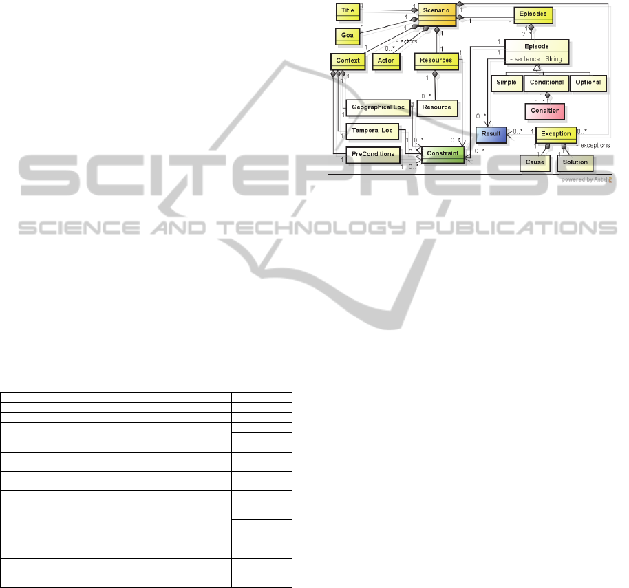
Figure 1 shows a metamodel for scenario
description used in this work. It defines an abstract
syntax for a scenario using a class diagram.
Definition 1: According to our metamodel, a
scenario is a 7-tuple S = (Title, Goal, Context,
Resources, Actors, Episodes and Exceptions) and the
attributes Constraint and Result.
A scenario S must satisfy a goal that is reached
by performing its episodes. The episodes describe
the operational behavior of the situation, which
includes the main course of action and possible
alternatives. An exception can arise during the
execution of episodes, and indicates that there is an
obstacle to satisfy the goal. The treatment to this
exception does not need to satisfy the scenario goal.
Figure 1: Scenario metamodel.
The episodes of a scenario can be of three
different types: simple, conditional and optional.
Simple episodes are those necessary to complete the
scenario; Conditional episodes are those whose
occurrence depends on internal or external
condition, internal conditions can come from
scenario pre-conditions, resources, actors,
constraints or previous episodes; Optional episodes
are those that may or may not take place depending
on conditions that cannot be detailed.
A sequence of episodes implies a precedence
order, but a non-sequential order can be bounded by
the symbol “#”. This is used to describe parallel or
concurrent episodes (#<Episode Series>#).
The scenario language makes explicit the
sequential interactions among scenarios. Scenarios
can be connected to other scenarios through links,
yielding a complex network of relationships:
Integration Scenario gives an overview of the
relationship among several scenarios of the
application, since each integration scenario episode
corresponds to a scenario.
Sub-scenario is defined when an episode of a
scenario can be described by another scenario. This
allows the decomposition of complex scenarios,
facilitating both its writing and understanding.
Pre-condition is a relationship defined within the
context element of a scenario. A scenario that is pre-
condition to other must be executed first and so on.
Exception relationship is defined when a scenario is
used to detail the exceptional behavior of another.
The main scenario should be executed and an
ICEIS2015-17thInternationalConferenceonEnterpriseInformationSystems
496
exception must occur to execute the other one.
Constraint relationship is defined when a scenario is
used to detail non-functional aspects that prevent the
proper execution of another, which also give us an
order among the scenarios.
3.2 Linguistic Pattern Syntax
In order to reduce ambiguity in natural language
requirements descriptions, we have defined a
concrete syntax based on linguistic patterns for
describing scenario elements conform to this
metamodel (Figure 1).
Table 2 shows the different linguistic patterns
(template) for describing scenarios based on natural
language. The scenario model should be seen as a
syntax and structural guidelines to facilitate the
automated analysis (Leite et al., 2000).
In Table 2, + means composition, {x} means 0 or
more occurrences of x, () is used for grouping, |
stands for or and [x] denotes that x is optional.
Table 2: Linguistic patterns for describing scenarios.
TYPE
D
ESCRIPTION
Title
P
hrase | ([Actor | Resource] + Verb + Predicate)
Goal
[Actor | Resource] + Verb + Predicate
Context
{Geographical Location}+{Temporal Location}+{Pre-condition}
Geographical Loc.
P
hrase + {Constraint}
Temporal Location
P
hrase + {Constraint}
Pre-condition [Subject | Actor | Resource] + Verb + Predicate + {Constraint}
Resources
{Name} + {Constraint}
Actors
{Name}
Episodes
{ ( <Sequential Group> | <Non-Sequential Group> ) }
Sequential Group
<
Basic Sentence> <Basic Sentence> | <Sequential Group><Basic Sentence>
Non-Sequential Group
#
<Episode Series>#
Episode Series
<
Basic Sentence> <Basic Sentence> | < Episode Series><Basic Sentence>
Basic Sentence
<
Simple Episode> | <Conditional Episode> | <Optional Episode>
Simple Episode
<
I
d
> <Episode Sentence> C
R
Conditional Episode
<
I
d
> IF <Condition> THEN <Episode Sentence> C
R
Optional Episode
<
Id> [<Episode Sentence>] C
R
Exceptions
{Exception}
Exception
<
I
d
> IF <Cause> THEN <Solution>
Id Identifier
Episode Sentence
(([Actor | Resource] + Verb + Predicate) | ([Actor | Resource] +
[Verb] + Title)) + [(“with the result” | “such that”) {Result}] +
{Constraint}
Solution
((Verb + Predicate) | Title) + [(“with the result” | “such that”)
{Result}]
Condition/Cause/
Result
([Subject | Actor | Resource ] + [Verb] + Predicate) | Phrase
Constraint
([Subject | Actor | Resource ] + Must [Not] [Verb] + Predicate) |
Phrase
A simple episode is described as follows:
<Id> (([Actor | Resource] + (Verb + Predicate) |
([Actor | Resource] + [Verb] + Title)) + [(“with the
result” | “such that”) {Result}] + {Constraint}
An episode accesses or modifies resources and it is
executed by Actors. The relevant information for an
episode is the action performed (episode sentence).
Optionally, it is possible to add non-functional
requirements (Constraint) related to the episode and
to add expected results (Result).
A result is not a post-condition, because a post-
condition is a successful response of the system
when the main flow of episodes is carried out. A
Result or expected result is an internal condition and
it is important in Model-based Testing context.
An exception is described as follows:
<Id> IF <Cause> THEN ((Verb + Predicate) | Title)
+ [(“with the result” | “such that”) {Result}]
The first element of an exception is the identifier.
This is composed by the identifier of the episode
followed by the number of the exception (an episode
can throw several exceptions). The second element
is the Cause that triggers the exception, the third
element is the Solution to treat the exception, and
the Result attribute are the expected results at the
end of performs the Solution.
3.3 Analyzable Petri-Net Model
Petri-Net is a graphical and mathematical modeling
and analysis language for describing and studying
systems that are characterized as concurrent,
asynchronous, distributed, parallel, nondeterministic,
and/or stochastic.
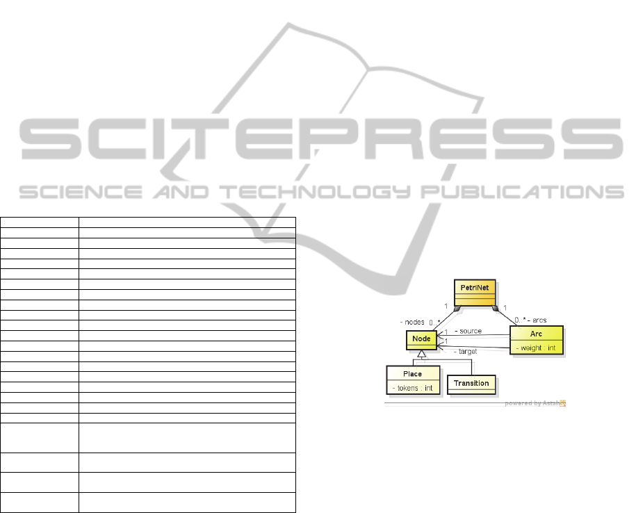
A Petri-Net (Figure 2) is composed of nodes that
denote places (Place) or transitions (Transition).
Nodes are linked together by arcs (Arc).
Figure 2: Petri-Net metamodel.
Transitions are active components. They model the
activities that can occur – events, thus changing the
state of the system. Transitions are only allowed to
fire if they are enabled, which means that all the pre-
conditions for the activity have been fulfilled.
Places are passive components and placeholders for
tokens. They model communication medium, buffer,
geographical location or a possible state (condition).
The current state of the system being modeled is
called marking which is given by the number of
tokens in each place.
Arcs are of two types: Input arcs start from places
and ends at transitions, while output arcs start at a
transition and end at a place.
When the transition fires, it removes tokens from
its input places and adds some at all of its output
MappingTextualScenariostoAnalyzablePetri-NetModels
497

places. The number of tokens removed/added
depends on the cardinality (weight) of each arc.
Definition 2. A place-transition Petri-Net is a five-
tuple PN = (P, T, F, W, M
0
) where P = {p
1
, p
2
, ...,
p
n
} is a finite set of places, T = {t
1
, t
2
, ..., t
m
} is a set
of transitions, F (P×T) (T×P) is a set of arcs, W
: F → {1, 2, ...} is a weight function, M
0
: P → {0, 1,
2, ...} is the initial marking and P T = .
4 MAPPING RULES
This section defines the transformation (Figure 3) to
generate a place-transition Petri-Net (instance of the
metamodel of Figure 2) from a scenario description
(instance of the metamodel of Figure 1). By an
automatic transformation, we can have more precise
requirements through the analysis of Petri-Nets.
Detailed mapping rules are described below.
Figure 3: Overview of the proposed method.
4.1 Initialization
The initial state (context) and the resources used by
the scenario are mapped into a Sub-Petri-Net
composed of Places generated from geographical
location, temporal location, pre-conditions and
constraints as follows:
Initially, one Place p with an initial token is
generated for the Scenario S:
→Place, p with p.name = S.title; p.tokens = 1;
For every pre-condition pc in Pre-conditions:
→Place, p with p.name = pc.name; p.tokens=1;
For every Constraint c in Context:
→Place, p with p.name = c.name; p.tokens=1;
For every Constraint c in Resources:
→Place, p with p.name = c.name; p.tokens=1;
Places generated from the context and the resources
are “input places” of the first episode of the
scenario.
4.2 Mapping Episodes
Initially, each one of the episodes is mapped into the
“transition” t (t.name = episode sentence) and its
internal “dummy places” (input dummy place p
id
and
output dummy place p
od
) of a Sub-Petri-Net. The
Conditions or Option to trigger the transition t are
mapped into “input places” with an initial token.
When episodes are performed, axception can
arise. An exception is mapped into the “transition”
t
ex
(t
ex
.name = solution) and its internal “places”
(output places for the results). The “output dummy
place” p
od
is linked to the transition t
ex
. The
“condition” or “cause” to trigger the transition t is
mapped into an “input place” with an initial token.
A Constraint is an “input place” (non-functional
requirement, resource and also time constraints) that
are needed in order to perform the transition t.
A result is an “output place” satisfied by an
internal condition of the transition t.
Places and Transitions are generated as follows:
For every Episode e in Episodes:
→Place, p
id
with p
id
.name =”IDummy_”+e.id;
→Transition, t with t.name =e.episode_sentence;
→Place, p
od
with p
od
.name =”ODummy_”+e.id;
→Arc, a with a.source = p
id
; a.target = t;
→Arc, a with a.source = t ; a.target = p
od
;
For every Constraint c in Episode e:
→Place, p: p.name = c.name; p.tokens = 1;
→Arc, a with a.source = p; a.target = t;
For every Result r in Episode e:
→Place, p with p.name = r.name;
→Arc, a with a.source = t; a.target = p;
For every Exception ex in Exceptions:
IF ex.id starts with e.id:
→Transition, t
ex
with t
ex
.name =ex.solution;
→Arc, a with a.source = p
od
; a.target = t
ex
;
IF ex.cause :
→Place, p: p.name=e.cause;p.tokens=1;
→Arc, a: a.source = p; a.target = t
ex
;
For every Result r in Exception ex:
→Place, p with p.name = r.name;
→Arc, a: a.source = t
ex
; a.target = p;
→ Remove exception ex from Exceptions;
IF |e.condition| > 0:
→Transition, t
else
with t
else
.name = “ELSE_”
+ e.episode_sentence;
→Arc, a with a.source = p
id
; a.target = t
else
;
→Arc, a with a.source = t
else
; a.target = p
od
;
For all Condition cd in Episode e:
→Place, p: p.name =cd.name; p.tokens=1;
→Arc, a with a.source = p; a.target = t;
IF |e.conditions| > 0 e has exceptions:
→ Remove Arc a between t
else
and p
od
;
ICEIS2015-17thInternationalConferenceonEnterpriseInformationSystems
498
→Transition, t
d
: t
d
.name =”TDummy_”+e.id;
→Arc, a with a.source = p
od
; a.target = t
d
;
→Place, p
od
: p
od
.name =”ODummy2_”+e.id;
→Arc, a with a.source = t
d
; a.target = p
od
;
→Arc, a with a.source = t
else
; a.target = p
od
;
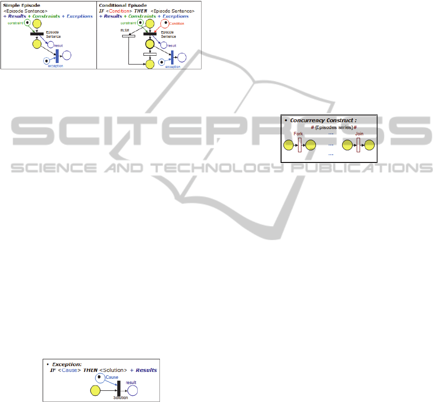
Transformation of episodes is shown in Figure 4.
Figure 4: Episode mapping rules.
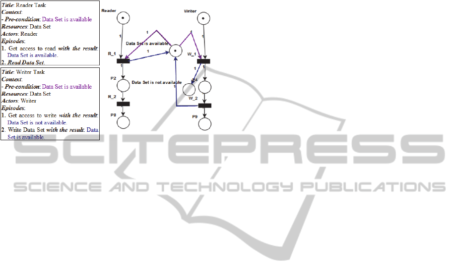
4.3 Mapping Exceptions
Each one of the remaining exceptions are mapped
into the “transition” t (t.name = solution) and its
internal “input dummy place” p
id
of a Sub-Petri-Net.
The “condition” or “cause” to trigger the transition t
is mapped into an “input place” with an initial token.
A result is an “output place” generated at the end
of perform the transition t.
Places and Transitions are generated as follows:
For every Exception ex in Exceptions:
→Place, p
id
with p
id
.name =”IDummy_”+ex.id;
→Transition, t with t.name =ex.solution;
→Arc, a with a.source = p
id
; a.target = t;
IF ex.cause :
→Place, p: p.name = e.cause; p.tokens =1;
→Arc, a with a.source = p; a.target = t;
For every Result r in Exception ex:
→Place, p with p.name = r.name;
→Arc, a with a.source = t; a.target = p;
The mapping of the exceptions or alternative flows
of the episodes is illustrated in Figure 5.
Figure 5: Exception mapping rules.
4.4 Mapping Concurrency Constructs
If the episode sentence of an episode e starts or ends
with the symbol “#”, this symbol describes the start
or the end (synchonization) of multiple concurrent
episodes, respectively. These situations are mapped
into two Sub-Petri-Nets composed of the transition
fork and the transition join, respectively (and their
internal input dummy place p
id
and output dummy
place p
od
).
For every Episode e in Episodes:
IF e.episode_sentence starts with “#”:
→Place, p
id
with p
id
.name =”IFork_”+e.id;
→Transition, t with t.name =”Fork_”+e.id;
→Place, p
od
with p
od
.name =”OFork_”+e.id;
→Arc, a with a.source = p
id
; a.target = t;
→Arc, a with a.source = t ; a.target = p
od
;
IF e.episode_sentence ends with “#”:
→Place, p
id
with p
id
.name =”IJoin_”+e.id;
→Transition, t with t.name =”Join_”+e.id;
→Place, p
od
with p
od
.name =”OJoin_”+e.id;
→Arc, a with a.source = p
id
; a.target = t;
→Arc, a with a.source = t ; a.target = p
od
;
The mapping of concurrency constructs is illustrated
in Figure 6.
Figure 6: Concurrency mapping rule.
4.5 Composing the Elements
This section explains the steps to compose a
complete Petri-Net model from the Sub-Petri-Nets
obtained of the elements of a scenario descrition.
Fusion Places: If an “input/output place”
derived from a scenario element appears like
“input/output place”, it should be merged into
the “input/output place” of the later one.
Linking Concurrent Episodes: The Sub-Petri-
Nets derived from the episodes between a “fork”
Sub-Petri-Net and a “join” Sub-Petri-Net must be
linked as concurrent Sub-Petri-Nets and
composed into a complete Sub-Petri-Net. The
“input dummy place” of the “Sub-Petri-Nets” of
the episodes are linked to the “transition” of the
“fork” Sub-Petri-Net. The “output dummy place”
of the “Sub-Petri-Nets” of the episodes are
linked to the “transition” of the “join” Sub-Petri-
Net.
Composing The Sub-Petri-Nets: First, all the
places generated from the context and the
resources are “input places” of the first transition
derived of the first episode. Second, the “output
dummy place” of the previous Sub-Petri-Net is
merged into the “input dummy place” of the later
one (Fusion Place).
MappingTextualScenariostoAnalyzablePetri-NetModels
499

4.6 Integration of Petri-Net Models
Scenarios are related to other scenarios by sequential
and non-sequential interactions. Two techniques,
“Fusion Places” and “Substitution Places” are used
to obtain a complete Petri-Net model of the
application (composed of Petri-Net models derived
from different scenarios).
Sequential Interactions: As described before, these
interactions could be of five types (integration
scenarios, pre-condition, constraint, sub-scenario
and exception) and determine the order in which the
scenarios should be executed (Section 3).
Non-sequential Interactions: Scenarios interact by
shared resources described as: pre-condition,
constraint and result. Through these relationships it
is possible to identify the scenarios that could be
executed concurrently.
If an “input/output place” derived from Pre-
Conditions, Constraints or Results of a scenario
appears like “input/output place” on other Petri-Net
model derived from other scenario, it should be
merged into the “input/output place” of the later one
(Fusion Places).
5 CASE STUDIES
In this section is described how the template and
mapping rules, detailed in Section 3 and 4 were used
to create the Petri-Net models of some classical
concurrency problems, using as basis their scenario
descriptions. The complete Petri-Net models were
obtained through the interconnection of Sub-Petri-
Nets and the integration of Petri-Net models.
The order which Petri-Net models are
constructed is: First, for each scenario, transforming
the context (“Pre-condition”) and the resources of
the scenario into a Sub-Petri-Net, transforming
“Episodes” of scenario into Sub-Petri-Nets
sequentially, linking “output places” (episode’s
results) into related episodes Sub-Petri-Nets, and
composing the “Sub-Petri-Nets” into a complete
Petri-Net model; Second, integration of Petri-Net
models by sequential & non-sequential interactions.
5.1 Bounded Producer-consumer
In multithreaded programs, there is often a division
of labor between threads. In one common pattern,
some threads are producers and some are consumers.
The producer generates one item and puts it in the
buffer. The consumer gets one item of the buffer and
extinguishes it (Downey, 2005).
Problem: Make sure that the producer won't try to
add an item into the buffer if it is full and that the
consumer won't try to remove an item from an
empty buffer.
The buffer is shared and it has only N positions
for items.
Solution: A “Customer” performs his consume only
when a “Producer” puts an item in the Buffer
(“Buffer is not empty”). A “Producer” produces an
item only when the “Buffer is not full”.
Figure 7 depicts the scenarios to describe a
simple solution for the “Producer-Consumer
Problem” and the corresponding Petri-Net model.
Figure 7: Bounded Producer-Consumer Petri-Net.
The output place “Buffer is not empty” of the
“Producer” is merged with the initial input place
“Buffer is not empty” of the “Consumer”. The
output place “Buffer is not full” of the “Consumer”
is merged with the initial input place “Buffer is not
full” of the “Producer”.
5.2 Readers-Writers Problem
The Reader-Writer Problem pertains to any situation
where a data structure, database, or file system is
read and modified by concurrent processes: Readers
and Writers. While the data structure is being written
or modified it is often necessary to bar other
processes from reading, in order to prevent a reader
from interrupting a modification in progress and
reading inconsistent or invalid data (Downey, 2005).
Problem: Allow multiple readers to read at the same
time. Only one single writer can access the shared
data at the same time.
Reader: only read the data set; it does not
perform any updates.
Writer: can both read and write.
Solution: Once a “Writer Task” is ready (“Data Set
is available”), it gets to perform its write as soon as
ICEIS2015-17thInternationalConferenceonEnterpriseInformationSystems
500
possible and locks (“Data Set is not available”) the
other “Writer” and “Reader Tasks”.
Figure 8 depicts the scenarios to describe a
simple solution for the “Readers-Writers Problem”
and the corresponding Petri-Net model.
Figure 8: Readers-Writers Problem Petri-Net Model.
The initial input place “Data Set is available” of
the “Reader” is merged with the initial input place
“Data Set is available” of the “Writer”. The output
place “Data Set is available” of the “Reader” is
merged with the output place “Data Set is
available” of the “Writer”.
6 CONCLUSIONS
This work proposes mapping rules for transforming
a specific natural language-based scenario model
into a Petri-Net model. The resulting Petri-Net
model can be analyzed using available tools (PIPE2,
2014). Such tools are able to identify the following
problems in a Petri Net model: boundedness, safety
and deadlock. As such, if this earlier feedback is
available, it is possible to trace backwards to
scenario descriptions and fix problems earlier on.
The main contributions of this work are
summarized as follows: (1) Describe and update an
abstract and concrete syntax for describing
scenarios. (2) Define mapping rules from Scenario
descriptions to Petri-Nets. (3) Express each mapping
rule in terms of “Data related issues” (Constraints,
Pre-Conditions and Results). (4) Define rules for
integrating Petri-Net models derived from different
scenarios of the application (modularity). (5)
Provide examples considering concurrent scenarios
in order to show the interactions by concurrency.
The contributions of this work provide
convenient ways to make explicit the non-sequential
interactions among scenarios by shared resources.
This fact can be used for further analysis of
properties (like deadlock and conflict) and testing.
Our future research plan will consider the
following tasks: (1) Define criteria to identify
inconsistency, incompleteness and incorrectness for
intra-scenario and inter-scenario relationships based
on analysis of structural and behavioral properties of
Petri-Nets. (2) Investigate strategies, which
automatically traverse the Petri-Net model to
generate the test scenarios based on path analysis
strategies. This strategy will take into account
interactions by “shared resources”.
REFERENCES
Andersson, M., Bergstrand, J., 1995. Formalizing Use
Cases with Message Sequence Charts. Master’s thesis.
Lund Inst. of Technology.
C & L., 2014. Scenarios & Lexicons. Available at:
http://pes.inf.puc-rio.br/cel.
Cockburn, A., 2001. Writing Effective Use Cases.
Addison-Wesley.
Downey, A. B., 2005. The Little Book of Semaphores.
Green Tea Press. Available at http://greenteapress.
com/semaphores.
Gutiérrez, J. J., Clémentine, N., Escalona, M. J., Mejías,
M., Ramos, I. M., 2008. Visualization of Use Cases
through Automatically Generated Activity Diagrams.
In: Czarnecki, K., Ober, I., Bruel, J.-M., Uhl, A.,
Völter, M. (eds.) MODELS. LNCS, volume 5301,
pages 83–96. Springer, Heidelberg.
Hsia, P., Samuel, J., Gao, J., Kung, D., Toyoshima, Y.,
Chen, C., 1994. Formal Approach to Scenario
Analysis. In IEEE Software, pages 33-41.
Lee, W. Cha, S. and Kwon, Y., 1998. Integration and
analysis of Use Cases Using Modular Petri Nets in
Requirements Engineering, In IEEE Transaction on
Software Engineering, volume 24, number 12, pages
1115-1130.
Lee, J., Pan, J. I., and Kuo, J. Y., 2001. Verifying
scenarios with time petri-nets. Inf. Softw. Technol.,
volume 43, number 13, pages 769–781.
Leite, J. C. S. P., Hadad, G., Doorn, J. and Kaplan, G.,
2000. A scenario construction process. Requirements
Engineering Journal, Springer-Verlag London
Limited, volume 5, number 1, pages 38-61.
PIPE2., 2014 Platform Independent Petri net Editor 2,
http://pipe2.sourceforge.net
Reisig, W., 1985. Petri Nets: An Introduction, Springer-
Verlag, Berlin, Heidelberg.
Somé, S., 2007. Petri Nets Based Formalization of Textual
Use Cases. Tech. Report in SITE, TR2007-11, Uni. of
Ottawa.
Zhao, J., Duan, Z., 2009. Verification of use case with
petri nets in requirement analysis. In Gervasi, O.,
Taniar, D., Murgante, B., Laganà, A., Mun, Y.,
Gavrilova, M. L. (eds.) ICCSA 2009, Part II. LNCS,
volume 5593, pages 29-42. Springer, Heidelberg.
MappingTextualScenariostoAnalyzablePetri-NetModels
501
