
Micro Grid Architecture for Line Fault Detection and Isolation
Maneesha Vinodini Ramesh, Neethu Mohan and Aryadevi Remanidevi Devidas
Amrita Center for wireless Networks and Applications, Amritapuri, Clappana P. O.,
Kollam, Kerala, India
Keywords: Micro Grid, Line Fault, Intelligent Module, Wireless Communication.
Abstract: One of the major problems power grids system face today is the inability to continuously deliver power at
the consumer side. The main reason for this is the occurrence of faults and its long term persistence within
the system. This persistence of faults causes the cascading failure of the system, thereby adversely affecting
the connected loads. Traditional methods of fault isolation cause the shutdown of power to a large area to
maintain the system stability. Today, localization of faults and its isolation is doing manually. Therefore, a
localized fault recovery mechanism is very essential to maintain the system’s stability after the occurrence
of a fault. In this paper, we have developed fast fault detection and isolation mechanism for single phase to
neutral line fault in a three phase islanded micro grid scenario. The fault detection and isolation during the
islanded operation mode of a micro grid is very critical, since bidirectional power flow is present. The fault
detection mechanism we developed can detect and isolate the fault within a few milliseconds and localize
the fault within a two second delay for both in single and bi-directional power flow scenarios. The proposed
system is capable of locating the exact faulted segment with the aid of the communication network
integrated into the power grid. The implemented system was tested with different ranges of fault current and
the analysis showed that the proposed system could localize the fault with less than a two second delay.
1 INTRODUCTION
The frequency of fault occurrence of the secondary
distribution grid as compared to the primary side is
considerably high. Most of the faults in a power
system results in a huge variation of electrical
parameters which will badly affect the operation of
the loads. In today’s distribution grid, whenever a
fault occurs in any part of the distribution grid, that
fault should be isolated from the distribution
transformer. This condition causes a long term
power cut in majority of the grid.
A micro grid is a small scale distribution
network, which is designed to provide power for a
local community. Whenever an abnormal condition
occurs in the main grid, the micro grid can work in
island mode. During the islanded mode of operation,
power sharing is present within the micro grid. The
power flow within the network is bidirectional,
which is based on the power demand. In order to
develop a fault detection mechanism in an island
micro grid scenario, the direction of power flow
should also be known.
In this paper, we proposed a three phase micro
grid system. This micro grid system includes smart
homes, which can act like a power supplier as well
as a consumer, and intelligent modules which are
present at each distribution pole. Most of the fault
detection and isolation mechanisms, which had
proposed previously in other works for a micro grid
system, were mainly in DC system. In most of the
previous work, fault detection and isolation
mechanism for micro grid system has done in the
DC system. Furthermore, most of the works used
ring type architecture for this DC micro grid system.
In this paper, we considered the AC micro grid
system with radial architecture. By considering this
system, we developed and implemented an
automatic fault detection, isolation and fast fault
localization mechanism.
The rest of the paper is structured as follows:
Section 2 presents the related works, section 3
explains the proposed system architecture, section 4
gives the fault detection and isolation method,
section 5 gives the fault localization method, section
6 gives the hardware design, section 7 gives the
hardware implementation, section 8 gives the
experimentation and analysis and section 9 gives the
conclusion.
250
Vinodini Ramesh M., Mohan N. and Devidas A..
Micro Grid Architecture for Line Fault Detection and Isolation.
DOI: 10.5220/0005454002500255
In Proceedings of the 4th International Conference on Smart Cities and Green ICT Systems (SMARTGREENS-2015), pages 250-255
ISBN: 978-989-758-105-2
Copyright
c
2015 SCITEPRESS (Science and Technology Publications, Lda.)

Figure 1: Three phase islanded micro grid architecture for fault detection and isolation.
2 RELATED WORK
A fault protection and isolation scheme for a DC
micro grid system was proposed in (Jae-Do and
Jared, 2013). In this scheme, the authors used the
current sensor to detect and isolate the fault with the
help of a master and slave controller, which is
associated with every segment of this loop type
micro grid system. But in the island mode of
operation, the protection schemes for the micro grid
system may be entirely different from the traditional
protection scheme since bidirectional power flow is
present. Different types of fault which occur at three
phase distribution system were compared in
(Cheraghi and Goodarz, 2011). The simulation
depicted that the magnitude of the fault current
varies widely for different types of fault in a three
phase system. In order to develop a protection
scheme for this system, knowledge about this huge
fault current was vital. An overview of the existing
protection schemes for the micro gird was given in
(Buigues, 2013). The protection scheme for a micro
grid should be tolerable to the dynamic topological
change due to changes in the connection and
disconnection of generators, load centres, storage
system and other switches.
A fault current detection method by analyzing
the current conditions at different relay locations did
in (Sanaye-Pasand and Khorashadi-Zadeh, 2003).
Whenever a fault occurs at the transmission line, the
current at each the relay location was subject to
change. The principle of variation of the current
sensor before and after the fault incidence was used
for fault detection and its classification in this work.
An over current protection for a micro grid
system with the help IED has been proposed in
(Voima, Kauhaniemi and Laaksonen, 2011).
According to them, a new over current protection
scheme is needed for a micro grid system when it is
operating islanded mode since the change in the
operating condition from grid connected mode to
islanded mode causes a drastic change in the
distribution network parameters. Detection of a fault
is done in this paper with the help of the
telecommunication communication system in
association with IEDs.
An approach of using wireless sensor networks
to power grid monitoring was given in (Fateh,
Govindarasu and Ajjarapu, 2013). According to this
paper, even though the bandwidth and latency was
the main bottlenecks for using wireless sensor
networks in a smart grid scenario, proper design of
the network could make wireless sensor networks
the best solution for power grid monitoring. The
authors used a hierarchical wireless sensor network
in this paper. Different communication technologies
and its requirements which are applicable in a smart
grid scenario were addressed in (Fateh, Govindarasu
and Ajjarapu, 2013).
MicroGridArchitectureforLineFaultDetectionandIsolation
251

Analysis of different communication
technologies gave in this paper with different
communication requirements like latency, reliability,
frequency and security. Study of wireless sensor
network for smart grid monitoring application gave
in (Gungor and Hancke, 2010). The authors did an
experimental study of WSN at different power grid
scenario and found that it can meet most of the
communication requirements needed for smart grid
communication.
3 MICROGRID ARCHITECTURE
FOR FAULT DETECTION AND
ISOLATION
In this work we considered a three phase micro grid,
which operates in islanded mode. Each smart home
in this system had the capability to generate power
from a renewable energy resource and stored it. In
order to maintained the system self sustaining, the
extra power generated within the system could share
among the load centres according to the power
demand. This sharing of power between the loads
was vital since the micro grid was not connected to
the regular power grid source. The system
architecture of the proposed system is given in
Figure1.
In the figure 1, the micro grid has nine
distribution poles named as Pole 1, Pole 2 …Pole 9
and each distribution pole is connected to each smart
home. In this work we considered only single phase
loads which were equally distributed along three
phases. We assumed that every load had a renewable
energy source and it will act both as a load and
generator. The extra power produced can also be
stored. The smart meter which was present at each
smart home can continuously monitor the
bidirectional power flows into the home as well as
away from the home. Since a three phase
distribution grid was considered in this work, the
distribution pole will have three power lines. In
order to monitor the three phase lines, we needed to
use three intelligent modules at each distribution
pole. If we have only had one intelligent module to
monitor the three phase lines, failure of this
intelligent module could cause the three phase lines
unobservable. Thus, intelligent modules for each
phase line would improve the robustness of the
system. At each distribution pole, the breakers
associated with an intelligent module. A control
station associated with the micro grid to control and
take decision according to data of the system.
4 FAULT DETACTION AND
ISOLATION METHOD
Power sharing is one of the key features of the
proposed micro grid system. Faults which may occur
in this three phase micro grid could cause the system
to unbalance and prevent the power sharing.
Therefore, a fault detection and isolation mechanism
is very essential for the continuous operation of the
system. In this work, only the single line to neutral
fault was considered since 95 % of the fault occurs
within a three phase system was this type of fault.
Each distribution pole was associated with three
intelligent modules for each phase line. Each
intelligent device was connected to a current sensor,
voltage sensor, circuit breaker, communication
module and a micro controller unit. These sensors
along with circuit breakers and communication
modules were connected to the micro controller. The
block diagram of an intelligent device is shown in
Figure 2. Current sensors and voltage sensors
continuously monitored the current and voltage
condition at each phase line. The processor unit at
each intelligent device continuously checked
whether the current values exceeded the allowable
lower and upper threshold limit. If the current sensor
value had exceeded the threshold limits, the circuit
breaker present at that phase line opened the circuit.
5 FAULT LOCALIZATION
METHOD
After the fault detection and isolation the intelligent
device continuously sent the sensed current value to
its neighbouring distribution pole’s intelligent
device. Whenever an intelligent device received a
message from its neighbour, it compared the
received value with its own sensed value. Each
intelligent device took one of the two decisions after
this comparison.
a. If the difference in current values of the
adjacent intelligent module was not a high
value, then no fault occurred between the two
poles and the status of the breaker was closed
condition.
b. If the difference in current values of the
adjacent intelligent module was a high value
then a fault occurred between the two poles and
it opened the breaker associated with that phase
line.
SMARTGREENS2015-4thInternationalConferenceonSmartCitiesandGreenICTSystems
252
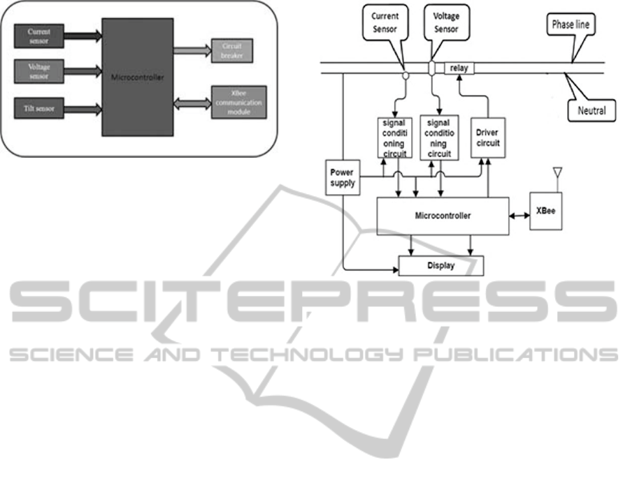
Figure 2: Block diagram of intelligent device.
Thus the breaker associated with the exact fault
location opened and the other breaker remained in
the closed. This helped to exactly locate the fault
within this islanded micro grid. The main advantage
of this localized fault isolation was that it avoids the
entire system shut down during faulted condition.
Besides, the other part of the distribution grid
remained in stable condition.
After localization of fault, the intelligent module
sent the information about fault location and the new
status of breaker condition to the control station. The
fault detection and isolation resulted in the formation
of two nano girds. These two nano grids could be a
power demanded region or power balanced region.
To change the power demanded region to a power
balanced region, the power re-routing mechanisms
could be introduced in future.
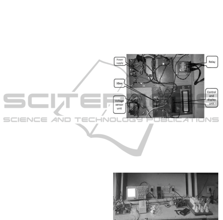
6 HARDWARE DESIGN
Fault detection and isolation had an important role
for maintain the stability of the proposed micro grid
system. A segment of the proposed micro grid
system with automatic fault detection and isolation
mechanism in a single phase system was
implemented in our laboratory. In this work, two
intelligent modules which were to be present at each
distribution pole have developed. Hardware
architecture of an intelligent module gave in Figure
3.
Whenever a fault occurred, the current and voltage
value changed. Therefore, in our system we used
these parameters to determine the fault condition.
Even though the fault was detected from the current
value, we also monitored the change in voltage in
our system. According to (Rebekah Hren Brian,
2011) the voltage drop for feeders should not exceed
2% and the voltage drop for branch circuit should
not exceed 3%, for efficient operation. In our
system, the voltage was continuously monitored to
ensure its variation has limited in this range.
Figure 3: Hardware architecture of an intelligent module.
Since the short circuit current due to single phase to
neutral line fault was very high, we have generated a
scaled down version of this high fault current in this
system to ensure the safety. The current sensor used
to monitor the over current should have had the
capability to tolerate our scaled down version of
over current. The current sensor with good
resolution would have increased the accuracy of
measurement. A transformer, which can provide
good isolation was calibrated in the voltage range of
44V to 240V and used as a voltage sensor in this
system since the RMS voltage used was 240V.
Consider figure 3. A signal conditioning circuit was
used in association with these sensors to manipulate
the sensor output in such a way that it met the
requirements for the next stage for future processing.
Since the output voltage range of the current sensor
was very small, we needed to amplify this voltage to
a range which could be easily detectable by the
micro controller. For that we used a signal condition
circuit with the selected current sensor. This would
also improve the resolution of the sensor. Since the
output voltage of the current sensor was in an AC
voltage range of 0-6V, we needed to manipulate the
signal in such a way that it could be given to the
micro controller unit. We needed a micro controller
unit of ADC resolution of atleast10 bit with good
operating speed. We selected PIC as our micro
controller unit since its ADC can provide required
resolution and have a wide operating voltage range
of 2V to 5.5V. Besides, it had a program memory of
8Kbytes and data memory of 368bytes and had a
good operating range of 20 MHz.
In the hardware implementation, we used relay
module for fault isolation. The relay module needed
MicroGridArchitectureforLineFaultDetectionandIsolation
253
for our system should have good ampere range so
that it could be controlled easily. In this system we
selected a relay with 30A current range with an
operation voltage of 12V DC. A communication
module was needed to implement the localization of
fault. The intelligent module was present at every
distribution pole and the distance between these
distributions poles were 40-60 meter. Therefore, our
communication module should have had a
communication range greater than this distance and
should have operated in unlicensed frequency band.
In order to power up the entire module from the
main supply, a step down transformer was needed.
Since the circuits in this intelligent module needed a
voltage of 0- 5V, we used a step down transformer
of 230 V to 6V and then the required voltage was
taken through regulators.
Each intelligent module had a current sensor and
a voltage sensor. These sensors continuously
monitored the current and the voltage condition of
the power line. The sensors were connected to the
micro controller unit through a signal conditioning
circuit. There was a circuit breaker connected with
the power line which helped to isolate the line when
anomalous conditions occurred. Operation of the
relay was controlled by the processor unit with the
help of a driver circuit. The XBee module present at
each intelligent module helped to communicate with
the neighbouring unit so that the intelligent module
could exactly locate the faulted part of the grid.
There was a display associated with the micro
controller unit. It indicated the current and voltage
condition of the line continuously. The power supply
module associated with this system took power
directly from the line and made it suitable and
available for all the circuits present within each
individual intelligent module.
7 HARDWARE
IMPLEMENTATION
We developed two intelligent modules in this
hardware. These modules were connected to a power
supply line and were tested with different load
conditions.
We used an ACS 714 current sensor with a
maximum current rating of 5A and a sensor
transformer with a voltage rating of 30-300V with a
current rating of 500mA. The micro controller unit
used in this module was PIC16F877A since it met
all the requirements for this design. An XBee
module with 2.4GHz frequency with 0dBm power
output was used in this project for wireless
communication (Rhidolabz, 2014).
The two intelligent modules were developed and
connected with the power line. Whenever we
simulated a faulted current within this system, the
two modules sensed the faulted current and
immediately tripped and communicated together and
exactly isolated the faulted part. After detecting the
faulted section, it isolated this part and maintained
the system’s stability.
Figure 4: Hardware implementation of intelligent module.
8 EXPERIMENTATION AND
ANALYSIS
We have tested the system with resistive and
inductive loads.
Figure 5: Integrated system.
In this test we have generated different scaled down
fault current and observe tripping time variation.
Test has done with both resistive and inductive
loads. Table 1 and table 2 show the fault current test
of intelligent module I with resistive loads and
inductive loads respectively.
Table 3 and 4 gave the fault current test of
intelligent module II with resistive and inductive
loads respectively. From the fault current test we
found that our system could locate the fault at
different over current conditions with almost the
same delay.
SMARTGREENS2015-4thInternationalConferenceonSmartCitiesandGreenICTSystems
254

Table 1: Fault current test of intelligent module I with
resistive loads.
Fault Current (in %) Fault localization time (sec)
115 1.15
163 1.06
190 1.16
211 1.05
238.3 1.15
Table 2: Fault current test of intelligent module I with
inductive loads.
Fault Current (in %) Fault localization time (sec)
133 1.19
195 1.15
Table 3: Fault current test of intelligent module II with
resistive loads.
Fault Current (in %) Fault localization time (sec)
116 1.01
133 1.02
163.33 1.02
200 1.1
Table 4: Fault current test of intelligent module II with
inductive loads.
Fault Current (in %) Fault localization time (sec)
133 1.12
195 1.28
9 CONCLUSIONS
Three phase micro grid architecture capable of
automatic fault detection and isolation mechanism
was proposed in this paper. The bidirectional power
flow inside the islanded micro grid made the fault
detection mechanism more challenging. A fault
detection mechanism developed in this work could
detect and isolate the fault and make the remaining
part of the grid in a balanced condition. The
proposed system was tested with different fault
current conditions and the results showed that the
proposed system could localize the fault within a 2
second delay. Even though a single phase to neutral
fault was very common in a three phase distribution
power system, other types of faults and its
occurrence was also important. Automatic fault
detection and localization of fault could not make
the system balanced. New approaches to power re-
establishment after fault detection and isolation
could also be done as future work.
ACKNOWLEDGEMENTS
We would like to express our sincere gratitude to our
beloved chancellor Sri. Mata Amritanandamayi Devi
(AMMA) for the immeasurable motivation and
guidance for doing this work.
REFERENCES
Jae-Do, Park., Jared, Candelaria., 2013. Fault Detection
and Isolation in Low voltage DC- Bus Micro grid
System. Power delivery IEEE Transaction on
201328.2 779- 787.
Cheraghi., Goodarz., 2011. Comparison of the Effects of
Phase to Ground Faults and Three Phase Faults in a
Micro-turbine Generation System. International
Review on Modelling & Simulations 4.2.
Buigues, G., Dyśko, A., Valverde, V., Zamora, I., &
Fernández, E., 2013. Microgrid Protection: Technical
challenges and existing techniques. Renew Energy
Power, Qual J, 11, 262.
Sanaye-Pasand, M., and H, Khorashadi-Zadeh., 2003.
Transmission line fault detection & phase selection
using ANN. International Conference on Power
Systems Transients—IPST.
Voima., Sampo., Kimmo, Kauhaniemi., and Hannu
Laaksonen., 2011. Novel protection approach for MV
microgrid. 21
st
International Conference on Electricity
Distribution.
Fateh., Benazir., Manimaran, Govindarasu., and
Venkataramana, Ajjarapu., 2013. Wireless network
design for transmission line monitoring in smart grid.
Smart Grid, IEEE Transactions on 4.2:1076-1086.
Fateh., Benazir., Manimaran, Govindarasu., and
Venkataramana, Ajjarapu., 2013. Wireless network
design for transmission line monitoring in smart grid.
Smart Grid, IEEE Transactions on 4.2: 1076-1086.
Gungor., Vehbi C., Bin Lu., and Gerhard P. Hancke. 2010.
Opportunities and challenges of wireless sensor
networks in smart grid. Industrial Electronics, IEEE
Transactions on 57.10 (2010): 3557-3564.
Rebekah Hren Brian. 2011. Code Red Notable changes in
the 2011 NEC [Online]:
Available: http://solarprofessional.com/articles/design-
installation/code-red-notable-changes-in-the-2011-nec.
Rhidolabz. 2014. XBee 1mV chip Antenna series 1
datasheet. [Online]:
Available: https://www.sparkfun.com/products/11215.
MicroGridArchitectureforLineFaultDetectionandIsolation
255
