Patch-based Terrain Synthesis
Leandro Cruz
1
, Luiz Velho
1
, Eric Galin
2
, Adrien Peytavie
2
and Eric Guerin
2
1
VISGRAF Lab, Instituto de Matematica Pura e Aplicada, Rio de Janeiro, Brazil
2
CNRS - LIRIS, Université de Lyon, Lyon, France
Keywords:
Terrain Synthesis, Data-driven Approach, Intuitive Control.
Abstract:
In this paper, we present an intuitive and controllable patch-based technique for terrain synthesis. Our method
is based on classical patch-based texture synthesis approaches. It generates a new terrain model by combining
patches extracted from a given set of exemplars, providing a control performed by a low frequency guide, a
categorization of exemplars, and a map for distributing these categories. Furthermore, we propose criteria to
validate the input, some structures to accelerate the patch choice, and a metric based on the process, these
structures, and some specificities of the data.
1 INTRODUCTION
The creation of virtual terrain is a widely studied topic
in computer graphics, because the large number of
possible applications. Despite this topic has been
studied for almost four decades, there is no definitive
solution that creates a complex model, with many dif-
ferent features, according to nature, and controlled in
a reasonably intuitive way.
In this paper, we introduce a method that con-
tributes for achieving those goals. Despite our ap-
proach has not been tested on the generation of an
entire and complex planet from an intuitive specifica-
tion, we are contributing with all those goals.
The creation of an entire planet involves many re-
search topics. We are focused on terrain synthesis.
There are more than one way to represent a terrain,
we use a regular Digital Elevation Model (DEM): a
matrix whereof each value represents the respective
height of the terrain. A complete survey for landscape
creation, and terrain representation and synthesis was
presented by (Smelik et al., 2014).
There is a seemingly trivial association between
the DEM and a grayscale image. So, we adapt a clas-
sical approach for image synthesis to the context of
terrain generation. Our method is based on the gluing
of patches extracted from real exemplars. The choice
of a patch-based technique allows to keep some land-
form features present in real data (and so, present on
nature). Furthermore, for creation of huge model this
larger unit (in comparison to a pixel) of the data syn-
thesized in each step accelerates the creation process.
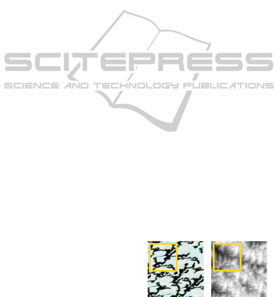
Applying directly Image Quilting method to gen-
erate a terrain does not produce realistic results as
shown in Figure 2. The generated terrain model is
not as good as the texture. The overlapped patches
are not well fitted and the global topographic features
(such as mountains and valleys) have a non natural
distribution. It is because the terrain exemplar is a
non-stationary model, and so, it does not have infor-
mation enough to create a good terrain. Thus, our
patch-based approach aims to deal with the specifici-
ties of terrains to obtain better results.
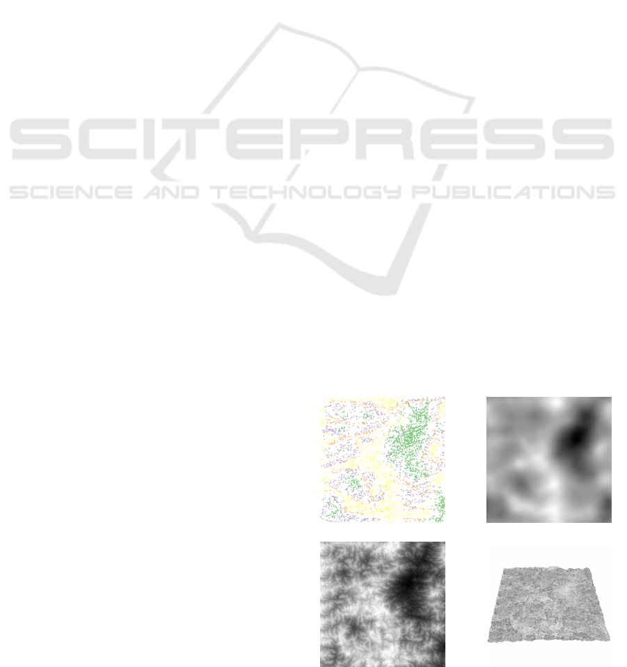
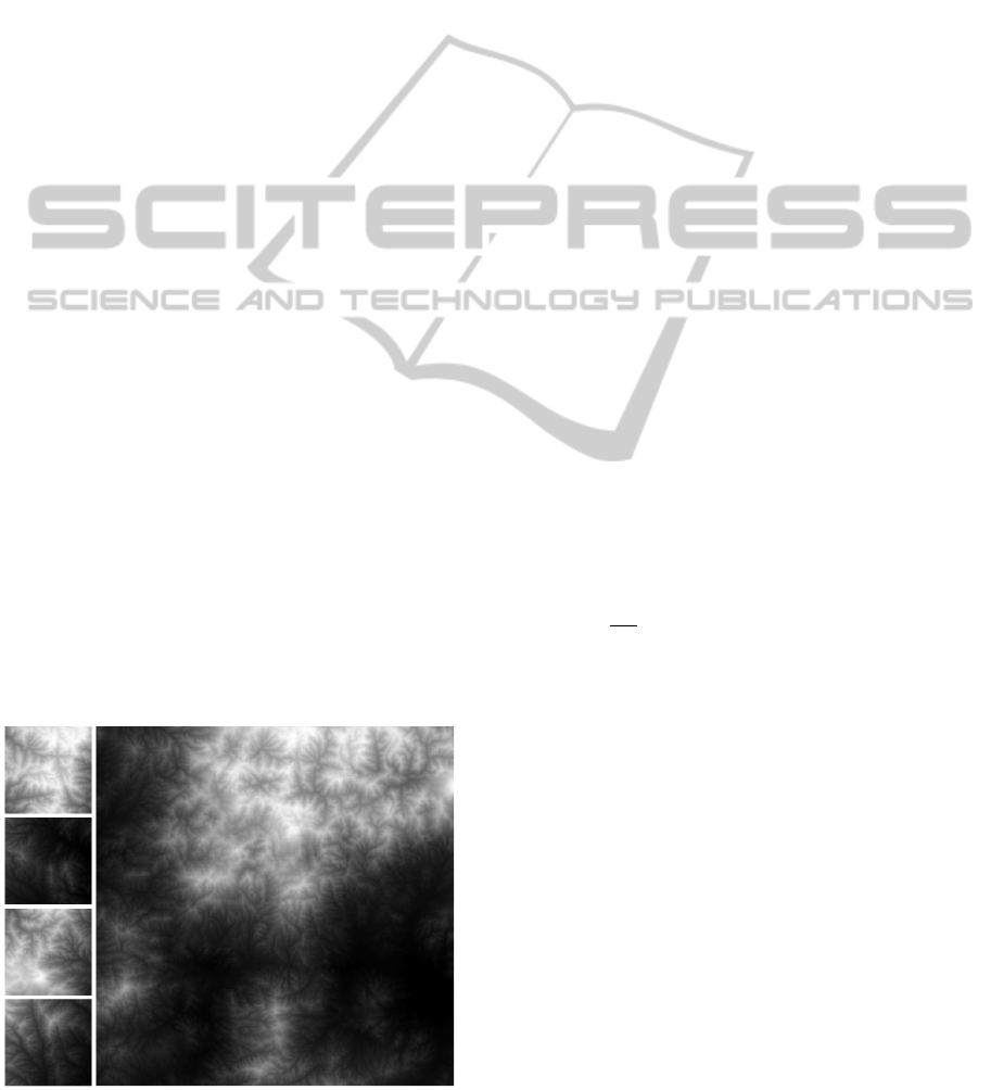
(a) (b)
(c) (d)
Figure 1: The specification (a) and generated guide (b); and
the synthesized DEM model (c) and its 3D view (d).
189
Cruz L., Velho L., Galin E., Peytavie A. and Guerin E..
Patch-based Terrain Synthesis.
DOI: 10.5220/0005360201890194
In Proceedings of the 10th International Conference on Computer Graphics Theory and Applications (GRAPP-2015), pages 189-194
ISBN: 978-989-758-087-1
Copyright
c
2015 SCITEPRESS (Science and Technology Publications, Lda.)
We provide an intuitive way to control the synthe-
sis, based on a guide, containing the coarse features
of the target model, and a map which associates parts
of the target with categories of the exemplars. Besides
the controlled behavior, our patch choice is based on
constraints derived from natural features, and some
structures to accelerate this process. Figure 1 shows
an example of a guided terrain modeling.
The main contributions of this work are:
• The creation and use of a guide, with the coarse
structures of the target, for synthesis control;
• An exemplar categorization and a map for associ-
ating regions of the target with these classes;
• A criterion for validation of the exemplars accord-
ing to the guide, and a rule for choosing a mini-
mum set of exemplars, into a large data set of ex-
emplars, able to cover the guide;
• An adaptation of the classical patch-based algo-
rithm including, besides of control, a new opti-
mization structure for patch choice, and a new
patch insertion approach (both based on the ge-
ometric nature of the data)
In this paper, we will present, in Section 2, some
works related to terrain synthesis, emphasizing the
patch-based approaches. In Section 3, we will intro-
duce our controlled patch-based technique for terrain
synthesis, explaining the creation and use of control
structures, introducing a new metric for patch choice,
a new patch insertion approach. The input validation,
and exemplar selection will be present in Section 4.
Finally, in Section 5, we will present some conclu-
sions and future works.
2 RELATED WORKS
Terrain synthesis is a widely studied problem in com-
puter graphics. It began by the use of procedural ap-
proaches (Musgrave et al., 1989). But, the recent re-
searches are based on simulation of natural phenom-
ena (Genevaux et al., 2013), or on composition of
structures taken on real data (Zhou et al., 2007).
There are many pixel-based methods for texture
synthesis that can be used for terrain synthesis (Lefeb-
vre and Hoppe, 2005). But, in general, they are con-
cerned to create a big homogeneous model with the
features contained in a provided exemplar.
(Han et al., 2008) proposed a pixel-based ap-
proach using a graph of exemplars in multiscale. This
new structure allows the synthesis to create an het-
erogeneous model, and possibly with an infinity res-
olution. (Cruz et al., 2013) adapted this approach for
terrain synthesis.
Patch-based Approaches
Patch-based synthesis methods (Efros and Freeman,
2001) create a model by covering the target using
patches taken from a given exemplar, placing them
with some predefined overlapping over the already
synthesized parts of model. The choice of which
patch will be chosen depends on some metric based
on comparison of the overlapping regions and, even-
tually, comparing some features of a control model.
After the choice of which patch will be inserted, a cut
is calculated, into the overlapping region, separating
the old part and the new one. Our synthesis approach
is similar, but it includes a more sophisticated control
and some adaptation based on the nature of the data.
An extension of the Image Quilting (Efros and
Freeman, 2001), presented by (Lasram and Lefebvre,
2012), performs the insertion of a set of patches in
parallel. The authors introduced an iterative method
whose, in each step, it is necessary to choose a patch
for each cell of the grid, define the cut and insert it in
the case when there is an improvement of the synthe-
sis quality (based on a specific metric). Our synthesis
approach is sequential. But, it is seemingly easy to ex-
tend that method to use our control and patch choice
and insertion approaches.
(Zhou et al., 2007) proposed a patch-based
method for terrain synthesis, creating the new model
by gluing patches taken from an exemplar. They also
provide a map with the main desired ridges or valleys
for controlling the synthesis. During the synthesis, the
patches are chosen by matching of a descriptor based
on these features. This control approach is based on
features in an intermediate scale. Our main concern
is to control features in a higher scale. Although, it
is possible to add their feature map in our synthesis
improving the control.
(Freeman et al., 2002) proposed a super-resolution
approach for image synthesis. This approach chooses
the patches by comparing a low frequency on a base
image (like our guide) and it matches the high fre-
quency in an overlapping region. Our approach is
similar, improving the control and the patch choice
(a) (b)
Figure 2: These results were generated using the exemplar
shown in yellow square through the Image Quilting method.
GRAPP2015-InternationalConferenceonComputerGraphicsTheoryandApplications
190
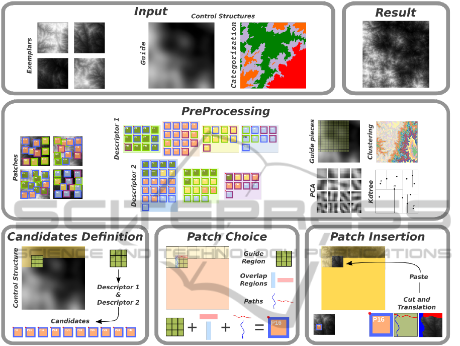
Figure 3: The method begins by the input definition: exemplars, and control structures. Following, in the synthesis step, we
choose a patch for each part of the grid. The result is a terrain model, with the predefined size and features.
and insertion.
3 PATCH-BASED TERRAIN
SYNTHESIS
The synthesis process is based on a sequential choice
and insertion of patches. Figure 3 shows the pipeline
of our method. The essence of the synthesis method
is the creation of a grid of overlapped regions, onto
the target area, and for each part of this grid to find
a patch well fitted to the pre-synthesized parts. This
search is performed by analyzing each possible patch
of the exemplars, based on some rules.
We will present a patch-based technique for ter-
rain synthesis. The input of our method is a set of
exemplars and the control models. The first control
model is the guide: a DEM, with the same resolution
of the target model, containing the desired low fre-
quency. The second one, is the categorization map: an
image splitted in some regions, and associating each
region with a class of exemplars (the exemplars are
pre-categorized according to some feature). We will
talk about control structures in Subsection 3.1.
The synthesis begins by the definition of which
patches are candidates to be inserted in the current
part. It is a subset of all possible patches, such that,
they are compatible to the respective region of the tar-
get (relative to some rule). The rules for candidates
definition will be discussed in Subsection 3.2. The
initial candidates set has a large number of possible
patches, chosen with high level criteria. These cri-
teria aim to match the coarse features of the patches
and the control structures. They are able to choose the
candidates by a low cost comparison.
After having applied these high level criteria, we
have to choose the patches that have a good matching
on the overlapping regions. We achieve it using low
level criteria, i.e. rules for performing a more detailed
comparison. Furthermore, it is necessary to define the
cut to split the pre-synthesized part of the part came
from the chosen patch. These steps will be present in
Patch-basedTerrainSynthesis
191
Subsection 3.3.
We will also talk about, in Subsection 3.3, the
classical cutting and pasting approach for patch inser-
tion, and the blending into the overlapping region to
remove seam discontinuities, applied after the patch
insertion. Furthermore, because we know that our
data is a terrain, we can perform some small vertical
translation on the patches, to improve the matching,
before the insertion. We will present this approach on
Subsection 3.4.
Finally, in Subsection 3.5 we will talk about the
processing optimizations. We will describe the accel-
eration structures, created in the preprocessing step,
and how they optimize the patch choice.
3.1 Control
The guide is a very important structure for control.
It contains the macro structures desired for the model,
e.g. where there are mountains, canyons, big plateaus,
etc. It also contains an implicit categorization of the
exemplars, since it has a wide range of height, and so
each exemplars, in general, can be only used in some
parts of the model. Also, it is a continuous model,
and so it helps the method to guarantee a continuous
synthesis. Furthermore, it guarantees that the patch
choice respects a coherent flow of the data.
We can create the guide by filtering an existing ter-
rain model (when we want the same macro features,
but with different details). Another possibility is to
use sketches to specify the macro structures (Tasse
et al., 2014). Another possibility is to use some kind
of brushes or seeds based on features extracted from
the exemplars. Figure 1 shows an example of a guide
created from a set of seeds related to four different
classes of heights.
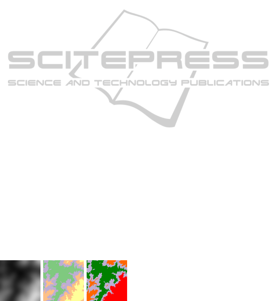
The map of categories can be based on a subdivi-
sion of the guide by clustering of heights. The clus-
tering process creates a set of regions associated to
the respective class. This map can be created by set-
ting which regions will be associated with each cate-
gory of exemplars. Of course, this association must
be enough to cover the entire target model, and must
have intersection to be able to synthesize the transi-
tion areas. Furthermore, in the association of regions
and categories we can relate regions of same height
to different categories, and we can relate a category
Figure 4: The categorization map.
to more than one level of heights (since the exemplars
have the entire range of heights). Figure 4 shows an
example of map created with these features.
3.2 Candidates Definition
In general, in this kind of approach, we find the best
patch by comparison of the overlapped region of the
pre-synthesized part and of each possible patch from
exemplars. However, depending on the amount of in-
put data, the brute force strategy is prohibitive.
The initialization of candidates uses high level cri-
teria, whereof we can take some decision that discards
a big amount of data by a low cost. And, we can use
more than one acceleration structure, like a chain of
processing, by removal of patches from the candidates
set. After that, to obtain a good patch matching, we
have to satisfy more specific constraints.
The acceleration structures are created based on
some descriptor D that represents a patch by a tuple
of k numbers (where k is much smaller than the patch
size). These structures are Hash Tables H whose keys
are k-tuples obtained by clustering the representation
of the patches given by D.
We have a descriptor D
i
, and the respective H
i
, for
each control structure. During the synthesis, the re-
gion being synthesized is also represented by D
i
and
it is compared to the keys of H
i
to determine which
clusters are closer (possibly more than one). Hence,
we obtain the candidates resembling to the control,
according to the feature described by D
i
, without
analysing individually all possible patches.
The first criterion for candidates definition is the
categorization. Its descriptor is the exemplar catego-
rization. It can be done by a user, or using some other
exemplar descriptor. We associate each category to
a number, and so, during the synthesis we will only
consider the patches on exemplars which the class is
contained in the respective region on the map. This
criterion selects a big amount of candidates. Thus, we
are also chaining other rules more constrained.
The second criterion is based on the low resolu-
tion structures. We can compare the average height
of the guide region and the one of the patch, but it is
a poor comparison, inasmuch as extremely different
distributions of heights can have the same average.
To improve the comparison, we divide this region in a
block of N ×N pieces, and we compare the average of
each piece. These pieces are created using a box filter,
and we opt for N = 3. In our tests, bigger values for
N have caused overconstrained matching.
Another structure is related to a more compact de-
scription of the overlapping regions. We tested the
clustering using the PCA representation (described on
GRAPP2015-InternationalConferenceonComputerGraphicsTheoryandApplications
192
Subsection 3.5) and the height average. The PCA
is a global representation, while the blocks represent
better local features. Because of this, the second ap-
proach provided a better cut definition.
3.3 Patch Choice and Insertion
The candidates are patches well globally fitted to
the desired macro structures, chosen according to the
control structures. But we also have to guarantee that
micro structures are also being well matched. For this
purpose, we will use low level criteria (and thus more
expensive tests).
This choice is achieved by comparison of the
patch with the guide region related to the part is being
synthesized G (using euclidean distance), the overlap-
ping region matching O, and the cost of the cut P. It
is performed by a solution of an optimization problem
based on the following the energy function M:
M(p, c) = αG(p, c) + βO(p, c) +γP(p, c) (1)
where α, β and γ are given parameters.
If the overlapping region matching is close enough
(big beta) we can use a greedy algorithm to calculate
the path (Efros and Freeman, 2001). This solution
create a path by local decision. So, it is not neces-
sary the global best cut. In general, the priority for
the overlapping matching can harm the guide fitting.
So, we prefer to use a better path creation approach,
based on Dynamic Programming (Lasram and Lefeb-
vre, 2012). It is more expensive, but it allows us pri-
oritize the global feature matching.
The classical approach for patch insertion con-
sists in cutting it and paste the respective area (Efros
and Freeman, 2001). Nevertheless, we can apply a
blending of the transition area using Poisson Blending
(Zhou et al., 2007) or using a smooth interpolation. In
both cases the calculation of the path can be avoided.
Figure 5: A terrain synthesized using our approach.
But, to guarantee a good matching, and so a good
insertion, we can apply a vertical translation of the
patch, and so add this translation to the patch before
inserting it. The calculation of the optimal translation
will be explained in the next subsection.
3.4 Vertical Translation
Some works apply a patch deformation to improve the
matching (Lasram and Lefebvre, 2012). However, we
avoided this kind of deformation because it could cre-
ate unnatural artifacts (unnatural in the sense: forms
which are impossible to exist in the nature).
However, we can take advantage of the geometric
nature of the data and apply some rigid transformation
into the patch to reduce the seam error. The patch
representation is a descriptor invariant to translations
in the domain. Furthermore, we compare the region in
the target with all similar candidates in the exemplar,
and so all possible translations of the patch over the
target have been implicitly performed. Moreover, we
can perform a translation in the height direction.
So, let p the position in the target where we will
insert the patch, and c the patch candidate. The best
height translation can be achieved by solving the fol-
lowing optimization problem:
¯
h = min
h∈ R
kB(T, p) −V (B(E, c), h)k
2
(2)
where B(A, x) is the function which returns the block
(with a predefined size) of A origined in the position x,
and V (A, h) the height translation of all points of the
DEM (or the block) A by the scalar h. The solution of
the optimization problem is:
¯
h =
1
nm
n
∑
i=0
m
∑
j=0
B(T, p)
i, j
− B(E, c)
i, j
(3)
Another advantage of the vertical translation is
that we can create a model whose the height range is
bigger than the input one. Of course, it is not interest-
ing to increase a lot this range, because some natural
phenomena depends on the height. But, small trans-
lations are not in contradiction to nature. The candi-
dates selection by comparison with the guide guaran-
tees that the translation of the chosen patch is small,
but if |h| > λ (for a given small λ > 0) the translation
will be not considered.
3.5 Processing Optimization
All acceleration structures are created in the prepro-
cessing stage. We perform the clustering using the k-
means algorithm. The choice of k aims to avoid small
clusters, otherwise we could have small candidate sets
(and then, an inefficient patch choice).
Patch-basedTerrainSynthesis
193

Another optimization regards the overlapping re-
gion comparison. We reduce their dimension by use
of Principal Component Analysis - PCA (Lefebvre
and Hoppe, 2005), and find the best matching by the
Nearest Neighbor method (Freeman et al., 2002). The
PCA basis and kd-tree used in the second method is
also created in the preprocessing stage.
Finally, in the optimization performed in the patch
choice step, the most expensive calculation refers to
the path creation. So, we can solve this problem in
two steps. The first one keeps the candidates close to
the optimal one defined by G and O. And, the second
step calculates the path for all remainder candidates
and pick the best.
4 INPUT
The quality of the synthesis depends on the choice of
the exemplars. If the amount of the data is too small
there is not enough information to perform an ade-
quate synthesis. However, a huge amount of redun-
dant data increases significantly the processing cost.
In general, in texture synthesis work, the user pro-
vides the exemplars. In our approach, it is extremely
important that the exemplars be able to cover the
guide. So, to avoid many trial and errors, we perform
an input validation. It is performed by checking if all
blocks in the guide are related to a minimum amount
of patches from exemplars. In general, we ask for
this minimum be greater than 500 candidates, to have
many alternatives for the next criteria.
In cases where the synthesis is performed with-
out a guide, we have to guarantee that the exemplars
are compatible: i.e. all exemplars have an enough
amount of patches in the same range of height of
patches in other exemplars. It is necessary that the
synthesis uses patches from all exemplars without big
discontinuities. When we use a guide, an adequate
coverture has this validation implicitly. The compati-
bility of patches is also performed by the comparison
of blocks of piece (analogous to the comparison with
the guide).
Furthermore, we cluster the patches from exem-
plars according to the blocks of average of pieces, and
create the categorization according to this clustering.
From this division, the user can create the categoriza-
tion map.
5 CONCLUSION
We introduced a patch-based approach for terrain syn-
thesis. The focus of our approach is the synthesis con-
trol. Even it has been proposed a control of structures,
a future work for this research is the improvement
of the creation and use of these elements. We can
include the Ridges and Valleys control (as in (Zhou
et al., 2007)), and improve the coarse structures cre-
ation for the guide.
Another possible guide creation approach is based
on hydrology. The user can place vectors related to
water flow. Thus, we can fill the entire area, by inter-
polating them. Mathematically, the flow is the gradi-
ent of the DEM. So, we can integrate them for gener-
ating the guide.
Despite of the advances for terrain synthesis, there
is a lack of high level methods for complex models
creation, and methods that combines different kinds
of nature elements. The main future work for this re-
search is to pursuit these goals.
ACKNOWLEDGEMENTS
The first author was being supported by CAPES, for
the development of part of this research at LIRIS, and
by CNPq for the rest of his PhD at VISGRAF.
REFERENCES
Cruz, L., Ganacim, F., Lúcio, D., Velho, L., and
de Figueiredo, L. H. (2013). Exemplar-based terrain
synthesis. SIBGRAPI WIP.
Efros, A. A. and Freeman, W. T. (2001). Image quilting for
texture synthesis and transfer. ACM SIGGRAPH.
Freeman, W. T., Jones, T. R., and Pasztor, E. C. (2002).
Example-based super-resolution. Computer Graphics
and Applications.
Genevaux, J.-D., Galin, E., Guerin, E., Peytavie, A., and
Benes, B. (2013). Terrain generation using procedural
models based on hydrology. SIGGRAPH.
Han, C., Risser, E., Ramamoorthi, R., and Grinspun, E.
(2008). Multiscale texture synthesis. SIGGRAPH.
Lasram, A. and Lefebvre, S. (2012). Parallel patch-based
texture synthesis. High Performance Graphics confer-
ence proceedings.
Lefebvre, S. and Hoppe, H. (2005). Parallel controllable
texture synthesis. SIGGRAPH.
Musgrave, F., Kolb, C., and Mace, R. (1989). The synthesis
and rendering of eroded fractal terrains. SIGGRAPH.
Smelik, R., Tutenel, T., Bidarra, R., and Benes, B. (2014).
A survey on procedural modeling for virtual worlds.
Computer Graphics Forum.
Tasse, F. P., Emilien, A., Cani, M.-P., Hahmann, S., and
Bernhardt, A. (2014). First person sketch-based ter-
rain editing. Graphics Interface Conference.
Zhou, H., Sun, J., Turk, G., and Rehg, J. (2007). Terrain
synthesis from digital elevation models. IEEE Trans-
actions on Visualization and Computer Graphics.
GRAPP2015-InternationalConferenceonComputerGraphicsTheoryandApplications
194
