
Shape-from-Silhouettes Algorithm with Built-in
Occlusion Detection and Removal
Maarten Slembrouck
1
, Dimitri Van Cauwelaert
1
, Peter Veelaert
1
and Wilfried Philips
1,2
1
TELIN dept. IPI/iMinds, Ghent University, Valentin Vaerwyckweg 1, Ghent, Belgium
2
TELIN dept. IPI/iMinds, Ghent University, Sint-Pietersnieuwstraat 41, 9000, Ghent, Belgium
Keywords:
Multi-camera, Occlusion, Visual Hull, 3D Modelling.
Abstract:
Occlusion and inferior foreground/background segmentation still poses a big problem to 3D reconstruction
from a set of images in a multi-camera system because it has a destructive nature on the reconstruction if one
or more of the cameras do not see the object properly. We propose a method to obtain a 3D reconstruction
which takes into account the possibility of occlusion by combining the information of all cameras in the multi-
camera setup. The proposed algorithm tries to find a consensus of geometrical predicates that most cameras
can agree on. The results show a performance with an average error lower than 2cm on the centroid of a person
in case of perfect input silhouettes. We also show that tracking results are significantly improved in a room
with a lot of occlusion.
1 INTRODUCTION
Shape-from-silhouette algorithms are widely used to
reconstruct a 3D object from a set of images and
perform very well in case of artificial circumstances.
However, in the real world occlusions are common
to occur. Occlusion has a destructive nature on tra-
ditional shape-from-silhouettes algorithms because it
carves away a part of the volume that should be-
long to the object. A person may for instance be
partially occluded from a camera viewpoint, result-
ing in only half of the person becoming foreground,
which is not an immediate problem, but since the
location of occlusion at that point is unknown, 3D
reconstruction will become very hard for traditional
shape-from-silhouettes algorithms (visual hull) (Lau-
rentini, 1994; Laurentini, 1997; Laurentini, 1999). In
(Guan et al., 2006) this problem is tackled by try-
ing to find the occluded pixels in the camera view
by using prior knowledge about occluders. Occlud-
ers most often give birth to straight lines in the fore-
ground/background segmentation. When this is not
the case however, the algorithm will fail to recover
occluded parts.
Ober-Gecks et al.also uses a shapes-from-
silhouettes algorithm in the field of robotics to re-
construct persons in an indoor environment for safety
reasons (Ober-Gecks et al., 2014). After their imple-
mentation of the visual hull concept, temporal filter-
ing is used to address detection failures of the cam-
eras. They also handle occlusion in each processing
step by integrating context knowledge in their track-
ing steps. In case of dynamic occlusion due to the
displacement of an object such as a chair this context
should be altered which is not the case in this algo-
rithm.
Stengel et al. presents an efficient reconstruc-
tion which exploits per-voxel data parallelism to effi-
ciently perform voxel-to-silhouette tests and handles
occlusion using a predefined modelling of moving ob-
ject such as robots to evaluate whether there is occlu-
sion or not (Stengel et al., 2012). This means that
the area has to be well defined and cannot be changed
easily. For example if the robots needs to move to
another corner of the working space this information
needs to be manually adapted into the system.
The automatic occlusion detection algorithm de-
scribed in (Slembrouck et al., 2014) creates an oc-
clusion map based on a voting mechanism taking into
account the position of the cameras and the number of
cameras that agree certain voxels are occluded while
a person walks around in the room. This algorithm
could potentially be refined in case of partial occlu-
sion as the proposed algorithm suffers from inaccura-
cies at the border of occluding objects, because only a
handful of voxels which are occluded are detected in
that phase.
On the other hand foreground/background seg-
635
Slembrouck M., Van Cauwelaert D., Veelaert P. and Philips W..
Shape-from-Silhouettes Algorithm with Built-in Occlusion Detection and Removal.
DOI: 10.5220/0005355506350642
In Proceedings of the 10th International Conference on Computer Vision Theory and Applications (VISAPP-2015), pages 635-642
ISBN: 978-989-758-091-8
Copyright
c
2015 SCITEPRESS (Science and Technology Publications, Lda.)

mentation algorithms are improving every year. How-
ever, in real world environments there are still some
major issues. For example when a person wears a
colour that is similar to the background, a lot of the
presumed foreground is not detected. The CDnet
2014 data set (Wang et al., 2014) shows there is still
room for improvement on foreground/background
segmentation algorithms. The best algorithm still
stays below 75% F-measure. Foreground/background
segmentation is not seldom a first step in a much
broader application. Therefore it is crucial this step
delivers reliable results.
In this paper we tackle the problem of occlu-
sion and bad foreground/background segmentation by
combining information from multiple cameras which
are observing the same scene from different view-
points. For instance when a person stands in front of
a wall which has a similar colour, this will be badly
detected from a camera that sees the person in front
of the wall, but the foreground segmentation will be
much better for viewpoints that see the person in front
of another background.
Our algorithm is able to reconstruct a complete
person even in the presence of occlusion where some
bodyparts are partially or fully occluded. Therefore
we use a consensus of geometrical predicates.
The contribution is twofold. The first is a way to
determine occluded parts of the scene for each cam-
era which makes it possible to remove occlusion and
the second is an effective way to improve the fore-
ground/background segmentation by combining mul-
tiple camera viewpoints, even tough our algorithm
was not designed for this.
In section 2 we take a look at the problem at hand
while in section 3 we will explain our algorithm in
detail. Section 4 will show promising results both for
simulations and for real data.
2 OCCLUSION PROBLEM
We propose a 3D reconstruction algorithm which dis-
tinguishes from a traditional shape-from-silhouettes
algorithm in the sense that the result does not equal
the enclosed volume of the backprojected silhouettes
from each camera. In case of occlusion or infe-
rior foreground/background segmentation the result-
ing 3D object is severely deformed using this ap-
proach. In case of full occlusion in at least one camera
view, no 3D shape is detected at all. With our algo-
rithm we will propose a way to obtain an acceptable
3D reconstruction even in the presence of severe oc-
clusion in multiple camera views without any knowl-
edge of the scene.
H
1
H
2
H
3
H
4
{+, +, +, +}
{+, −, +, +}
{−, +, +, +} {+, +, +, −}
{+, +, −, +}
{−, +, +, −}
{+, −, −, +}
{+, −, +, −}
{−, +, −, +}
C1
C2
Figure 1: Example of the construction of cells with two
cameras, which introduces the sign vector: {S
1
, S
2
, S
3
, S
4
}
where each S
j
represents + or − depending on which side
of the lines H
j
they occur.
The input of the algorithm is the same as that of
traditional shape-from-silhouettes algorithms: a cali-
brated camera environment and a synchronized set of
silhouette images.
2.1 Subdividing the Space in Cells
In this section we will explain the concept behind our
algorithm in two-dimensional space and for a convex
object. Extension to a three-dimensional space and
a non-convex object is straightforward. We use the
same notation as in chapter 6 about oriented matroids
of (Toth et al., 2004).
For a real matrix X := (x
1
, . . . , x
n
) ∈ (R
2
)
n
,
we consider the system of hyperplanes H
x
:=
(H
1
, . . . , H
n
) with
H
l
:= {γ ∈ R
2
: γ
T
x
l
= 0}. (1)
Let γ = (α
1
, α
2
, α
3
)
T
and x
l
= (x
l,1
, x
l,2
, 1)
T
, then
each vector x
l
induces an orientation on H
i
by defining
H
+
l
:= {γ ∈ R
2
: γ
T
x
l
> 0}, (2)
to be the positive side of H
l
, while H
−
l
is analogously
defined as the negative side of H
l
.
The projection of a convex 2D object on the sen-
sor of the cameras is a line segment. In figure 1 we
see that every pair of half planes H
i
and H
j
defines
a double cone where H
+
i
∩ H
+
j
is represented as the
blue area. They divide the space in cells. Every cell
C can be described by a unique sign vector. The signs
are based on the halfplanes that divide the space (H
1
,
H
2
, H
3
and H
4
in this example). The sign vector indi-
cates if a cell lies on the positive side of H
i
with + or
the negative side with −. A sign vector has the form
{S
1
, S
2
, . . . , S
M
}, (3)
VISAPP2015-InternationalConferenceonComputerVisionTheoryandApplications
636
where S
i
∈ {+,−}. In the case every camera has one
line segment, M := 2N with N the number of cameras.
Using the halfplanes we are able to define a cell as
the intersection of halfplanes, for instance
C = H
+
1
∩ H
+
2
∩ H
+
3
∩ H
+
4
(4)
is the dark blue region in figure 1, also known as the
visual hull.
Note that the length of the sign vector depends on
the number of line segments on the sensors of each
camera. Each interval on the line sensor introduces
two extra positions in the sign vector. For simplic-
ity, we assume one interval per camera sensor, but the
theory can be extended for higher complexity.
In that case, the traditional shape-from-silhouettes
algorithm only retains the cell where the sign vector
has pluses at all its positions. However, in case of
occlusion this is not enough. In figure 2 for instance
the orange object Ω is partially blocking the view of
camera 1. The traditional shape-from-silhouette algo-
rithms will lose a big part of the object in this case.
Only cell A will be kept. Our algorithm allows to add
cells to the traditional result, we call them augmenting
cells. These cells will contain minuses which practi-
cally means that the half planes corresponding to the
minus will be ignored so cell B can be added.
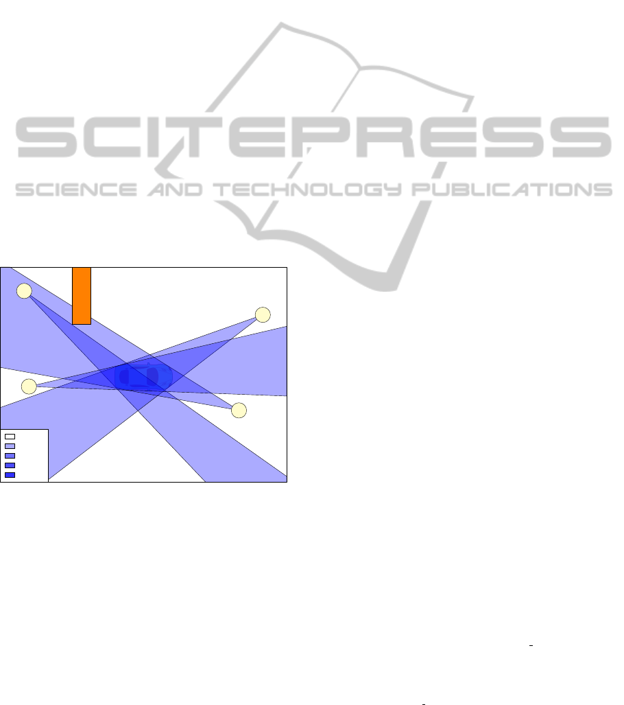
0 cams
1 cams
2 cams
3 cams
4 cams
C1
C2
C3
C4
A
B
C
D
E
F
Ω
Figure 2: Subdividing the space in cells with occlusion
present (occluder Ω is indicated in orange). Visually we
see that the desired solutions is the union of cell A and B
whereas cell C, D, E, F and all non-indicated cells should
be rejected.
2.2 Definitions
In this section we extend our explanation to three-
dimensional space because our algorithm works on
2D images which are a projection of a 3D scene. This
implicates that the line segments become silhouettes
on the sensor, but the theory about sign vectors still
holds, although the number of halfplanes increases
significantly. In three-dimensional space the cells are
only convex when the silhouettes are convex, but as
the property of convexity is not used, this does not
have serious implications.
In order to explain how our algorithm works, we
define the following symbols:
N total number of cameras in the multi-camera
setup
s
i
union of a finite number of filled contours
on the sensor of camera i, which corresponds
to the projection of the object(s) we like to
reconstruct
H traditional visual hull shape, the cell with
all pluses as sign vector
C
k
cell with index k which is uniquely
defined by a sign vector
We also define some operators:
Π
i
(A) projection of a convex shape A on the
sensor of camera i
Π
−1
i
(b
i
) reprojection of the silhouette b
i
from camera i
µ(s
i
) the size of a silhouette on the camera sensor
With these operators, we define some additional
symbols as shorthands:
h
i
:= Π
i
(H ) (5)
c
k
i
:= Π
i
(C
k
) (6)
These notations allow us to write the traditional
visual hull concept in a single formula
H :=
N
\
i=1
Π
−1
(s
i
). (7)
This formula expresses the concept of the shape-
from-silhouettes where the shape is the volume en-
closed by the backprojection of all silhouettes.
We define the camera consistency β
consist
(C
k
) of a
cell C
k
as the number of cameras where the projection
of this cell lies inside the silhouette,
β
consist
(C
k
) =
N
∑
i:c
k
i
⊆s
i
1. (8)
The camera consistency set A
consist set
of a cell C
k
is defined as the index set of camera indices where the
projection of the cell lies inside the silhouette,
A
consist set
(C
k
) = {i : c
i
⊆ s
i
}. (9)
Shape-from-SilhouettesAlgorithmwithBuilt-inOcclusionDetectionandRemoval
637

The covering fraction of a cell on camera i is the
fraction of c
k
i
that lies inside the silhouette s
i
, we ex-
press this with the following formula:
x
cov,i
(C
k
) :=
µ(c
k
i
∩ s
i
)
µ(c
k
i
)
. (10)
A cell C
k
is augmenting for camera i if the predi-
cate P
aug,i
(C
k
) holds true:
P
aug,i
(C
k
) :=
(c
k
i
⊆ s
i
) ∧ (c
k
i
6⊆ h
i
)
. (11)
It means that the cell is not a part of the projection of
H , but its projection lies inside the silhouette s
i
.
In section 3.3 we will explain the criteria that
decide if a cell is augmenting in three-dimensional
space. Therefore we define the predicate P
aug
(C
k
)
which holds true when these criteria for cell C
k
are
met. Note that this is different from equation 11.
P
aug
(C
k
) is a decision based on all camera evidence,
not just the projection on one camera.
A collection of cells is covering for camera i if the
projection of the union of the visual hull and all the
extra added cells cover the whole silhouette,
s
i
⊆
h
i
∪
[
k∈Φ
c
k
i
!!
, (12)
where Φ ⊂ K and K is the collection of all cells
3 PROPOSED ALGORITHM
The aim is to find the set of cells that is as small as
possible, but does explain the silhouettes in the best
possible way. The implementation operates in voxel
space because the number of intersections in three-
dimensional space scales very bad. The disadvantage
of using voxels is that we lose precision. For instance,
small cells might not be detected, but it significantly
improves runtime and small cells have little influence
on the precision of the result. All silhouettes and pro-
jections are handled as pixels since the input images
are also constructed with pixels.
We distinguish two major steps in our algorithm:
1. Calculation of the cells
2. Determination of the augmenting cells
3.1 Calculation of the Cells
A cell is a set of voxels where each voxel has the same
camera consistency set (equation 9 can also be applied
on voxels) and where all voxels which belong to the
set are connected with each other. Our approach to
cluster the voxels in the correct cells works as fol-
lows. First, we loop over all voxels and determine
for which cameras the projection of that voxel (v) is
a subset of the silhouette: Π
i
(v) ⊆ s
i
. Secondly, we
pick a voxel and grow in all directions over the vox-
els which have the same camera consistency set. This
process automatically halts when all voxels from the
same cell are found. All these voxels are clustered
together and stored. We also store the camera consis-
tency β
consist
(C
k
) for this cell (as we will also need
that later on). The voxels that are clustered, are re-
moved from the search space since each voxel belongs
to one cell only. We repeat the clustering process until
all voxels are clustered.
3.2 Determination of the Augmenting
Cells
Our algorithm itself operates on the cells (clusters of
voxels) we determined in the previous step. Let T
j
be the set of voxels which represents the 3D shape
of all augmenting cells and the visual hull, this shape
is updated after all cells with the same camera con-
sistency are evaluated which means j ∈ 0,1, . . . , N.
It does not make much sense to include cells with
very low camera consistency because they are usually
very big and have little chance to belong to the actual
object. The cells that are consistent for all cameras
(β
consist
(C
k
) = N) form the starting point of the algo-
rithm. Therefore the current solution is equal to the
result of the traditional visual hull algorithm:
T
0
= H (13)
We chose to evaluate the cells in descending or-
der of camera consistency because these cells have a
major chance to be augmenting than cells with lower
camera consistency. Once all cells with the same cam-
era consistency are evaluated, we update the 3D shape
T
j
by adding all augmenting cells. We define K as
K := {k : (β
consist
= N − j)∧P
aug
(C
k
)} in order to up-
date T
j−1
as
T
j
= T
j−1
∪
[
k∈K
C
k
!
. (14)
Note that it is possible to add occluded parts us-
ing this approach because cells, that project within the
silhouette in other cameras than the occluded camera,
will add the cell to the shape.
3.3 Criteria
In this section we will discuss different criteria to de-
termine whether a cell is augmenting or not. A sig-
nificant measure is the covering fraction of a cell C
k
VISAPP2015-InternationalConferenceonComputerVisionTheoryandApplications
638
(equation 10). This fraction between 0 and 1 indicates
the overlap of the projection of C
k
on camera i and its
filled silhouette s
i
.
We distinguish three different fraction after pro-
jecting a cell C
k
on a camera:
• x
non expl
: fraction that is part of the silhouette, but
was not already explained by the solution T
j−1
x
non
expl
:=
µ
c
k
i
∩ s
i
\ Π
i
(T
j−1
)
µ(c
k
i
)
(15)
• x
expl
: fraction that is part of the silhouette which
was already explained by another cell
x
expl
:=
µ
c
k
i
∩ Π
i
(T
j−1
)
µ(c
k
i
)
(16)
• x
extra
: fraction that is not part of the silhouette and
would add extra to the projection (only interesting
if that part is occluded)
x
extra
:=
µ
c
k
i
\ s
i
µ(c
k
i
)
(17)
These three parameters are used to determine
whether a cell is augmenting or not. In the results
section we discuss the value of the silhouette cover-
ing fractions, which will be called using the following
convention:
T
cov
:= silhouette covering threshold. (18)
We define a predicate P
cov,i
(C
k
) that indicates whether
or not the silhouette is covered by a cell:
P
cov,i
(C
k
) =
x
cov,i
(C
k
) > T
cov
. (19)
A cell is augmenting when there is a fraction of
its projection on the camera which is not already ex-
plained by the current solution x
non expl
> 0. How-
ever, for practical reasons due to imperfect calibra-
tion of the cameras and errors in the silhouettes, we
need to add some more restrictions. We found that
when the sum of the fraction that was not yet ex-
plained and the fraction that was already explained
was smaller than the fraction that added extra, the cell
was very unlikely to belong to the solution. On the
other hand, when the extra added part was smaller, it
is very likely that the cell contributes to the solution.
Also when the overlapping area between the silhou-
ette s
i
and the projection of the cell is high, the cell
should be added to the solution. This reasoning gave
us a criteria whether a cell is augmenting for a camera
or not:
x
non expl
> 0 ∧x
non expl
+ x
expl
> x
extra
∨ P
cov,i
(C
k
)
(20)
The silhouette covering part is added because in
some cases we noticed that due to imperfect camera
calibration the fractions where not sufficient to obtain
the correct result.
The number of cameras that agree to add cell C
k
is
equal to the number of cameras that meet the criteria
in equation 20. If this number is higher than or equal
to the camera consistency of that cell, we call the cell
augmenting and we add it to the 3D shape.
4 RESULTS
4.1 Camera Setup
In this section we will discuss the results of our algo-
rithm. For both the simulation and the real world test
setup we use the same calibration to provide a fair
comparison. The camera setup has seven cameras in
an 8 by 4 meters area. All cameras are mounted a lit-
tle over 3 meter on a truss construction. All cameras
are type Allied Vision Technologies Manta G-046C
(Allied Vision Technologies, ) cameras.
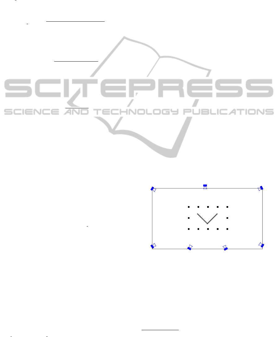
Figure 3 shows the xy-plane of our test setup. The
x-axis is horizontal (positive to the right) whereas the
y-axis is vertical (positive to the bottom). The V-
shaped occluder (in gray) is 2.12 metres heigh and
4 centimetres tick. The black squares are used as ref-
erence points for our measurements. There are 12 of
these reference points in total. The positions of these
points can be found in table 1
1
.
m0
m1
m2 m3 m4 m5 m6
m7
m8m9m10m11
v0
v1
v2
v3
v4
v5
C1
C2
C3
C4
C5
C6
C7
Figure 3: The test setup in our multi-camera environment.
A total of seven cameras is used with a V-shaped occluder in
the middle of the room (gray). The black squares m0-m11
are 12 reference points where we will evaluate our algo-
rithm.
4.2 Simulation
First we show that our algorithm works by using a
simulation with perfect silhouettes. We asked a per-
son to stand still at each of the positions indicated in
1
All the material for the experiments can be found on
our website. http://telin.ugent.be/∼mslembro/?q=node/18
Shape-from-SilhouettesAlgorithmwithBuilt-inOcclusionDetectionandRemoval
639
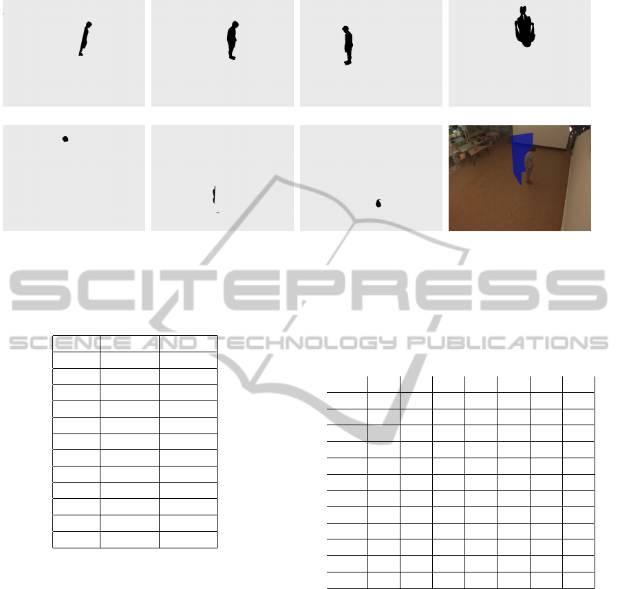
(a) mask of Cam 1 (b) mask of Cam 2 (c) mask of Cam 3 (d) mask of Cam 4
(e) mask of Cam 5 (f) mask of Cam 6 (g) mask of Cam 7 (h) Input of Cam 2
Figure 4: The foreground/background masks of the simulated camera setup. Cam 1, Cam 5, Cam 6 and Cam 7 are clearly
occluded due to the wooden V-shape in the scene. In figure (h) we show the actual input image with the simulated V-shaped
occluder present. The 3D reconstruction of these images can be found in figure 5.
Table 1: Coordinates of the reference points.
Point x (mm) y (mm)
m0 0 0
m1 0 800
m2 0 1600
m3 700 1600
m4 1400 1600
m5 2100 1600
m6 2800 1600
m7 2800 800
m8 2800 0
m9 2100 0
m10 1400 0
m11 700 0
figure 1 when the V-shaped occluder was not present.
We generated perfect foreground/background masks
to be used as the silhouette images. Then we gener-
ated the traditional visual hull, where we saved the
number of voxels and its centroid. The value of T
cov
is taken to be equal to 0.9 as our input silhouettes are
perfect. With this threshold we won’t add unwanted
cells because the coverage has to be rather big. De-
pending on the quality of the calibration and the input
silhouettes, this parameter might be changed for your
own experiments.
To test our algorithm, we generated new fore-
ground/background masks, but this time like if the V-
shaped occluder were present. This means a varying
number of occluded cameras for the 12 positions (ta-
ble 2). In figure 4 an example of the silhouette images
for position 10 is given. In figure 5 we see the 3D re-
construction from these 7 input masks. Although 4
out of 7 camera views are clearly occluded, our algo-
Table 2: Percentage of occlusion for all cameras on the 12
reference positions. 100% means fully occluded, 0% means
no occlusion in that view. There is rather severe occlusion,
even in multiple cameras for the same measuring point.
C1 C2 C3 C4 C5 C6 C7
m0 90 0 0 0 0 37 0
m1 10 99 0 0 0 0 0
m2 0 61 0 0 0 0 0
m3 0 0 0 93 0 0 0
m4 0 0 0 91 0 0 0
m5 0 0 82 38 0 0 0
m6 0 0 78 0 0 0 0
m7 0 0 86 0 0 0 0
m8 0 0 0 0 52 0 0
m9 0 0 0 0 85 0 5
m10 34 0 0 0 89 91 88
m11 94 0 0 0 0 92 95
rithm still succeeds to build a 3D reconstruction that
looks very much like the person.
The input masks with the occluder present are
used as input for our algorithm and the aim is to re-
cover the whole person even though some cameras are
occluded now. We compare both the number of voxels
and the centroid for (x,y) and (x,y,z) in figure 6. We
clearly see that our algorithm outperforms the tradi-
tional algorithm and the euclidean distance between
the centroid from our algorithm and the actual cen-
troid is lower than 20 mm (the voxel size).
4.3 Real World Data
In this section we will show that our proposed algo-
rithm also has a lot of potential in the real world. For
VISAPP2015-InternationalConferenceonComputerVisionTheoryandApplications
640
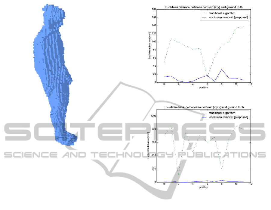
Figure 5: 3D reconstruction based on the input images of
figure 4. The complete person is reconstructed while only
4 out of 7 cameras could see the complete person. Voxel
size is 2cm x 2cm x 2cm. The traditional algorithm only
reconstructs a few voxels from the head of the person.
this we build an office environment in the multicam-
era setup we also used for simulations in the previous
section of this paper (figure 3). The desktop environ-
ment is composed by four static objects: a V-shaped
wall, a desk, a TV screen and a chair. In figure 7
we show the floorplan of this setup and the trajectory
we calculate from the seven input video streams. The
red dots represent the centroid of the person using the
traditional visual hull algorithm while the blue dots
represent the centroid calculated from the output of
our proposed algorithm. As you can see the blue dots
are much more represented than the red dots. Only
in 36.9% of the frame sets, the traditional visual hull
produces an output, while our algorithm produces a
position for all frame sets.
Note that the produced result in figure 7 is less
accurate than the results in the simulations. This is
mainly due to imperfect foreground/background seg-
mentation errors and calibration errors. In simulations
we produced perfect silhouettes as input for our al-
gorithm whereas in this realworld example we took
the output of the foreground/background segmenta-
tion method SUBSENSE (St-Charles et al., 2014).
This method performs among the best in the CD-
net 2014 Change Detection benchmark (Wang et al.,
2014), but still shows significant errors on the pro-
duced silhouettes.
(a) Error centroid (x,y)
(b) Error centroid (x,y,z)
Figure 6: Visual representation of euclidean distance be-
tween the (x,y)-coordinate (a) and between the (x,y,z)-
coordinate (b) of the centroid. The error on the z-coordinate
is most significant since the traditional algorithm only re-
construct part of the head, bringing the centroid to the head,
far away from the actual centroid. Projecting on the xy
plane ignores the z-coordinate, but even there we see that
our algorithm gives lower error rates. The mean absolute
error MAE for (a) is 10.52 mm and 87.52 mm and for (b)
13.38 mm and 616.42 mm for our algorithm and the tradi-
tional algorithm respectively.
5 CONCLUSION
In this paper we proposed an algorithm to generate
a 3D shape even if camera views are (partially or
fully) occluded without the need for any prior knowl-
edge of the scene (except for the camera calibration).
We showed promising result in both simulations and
real world examples which means it can have appli-
cations in real world environments where occlusion
is a significant problem. In the absence of occlu-
sion our algorithm can also be used because it also
repairs holes in the 3D shape due to imperfect fore-
ground/background segmentation because these holes
Shape-from-SilhouettesAlgorithmwithBuilt-inOcclusionDetectionandRemoval
641
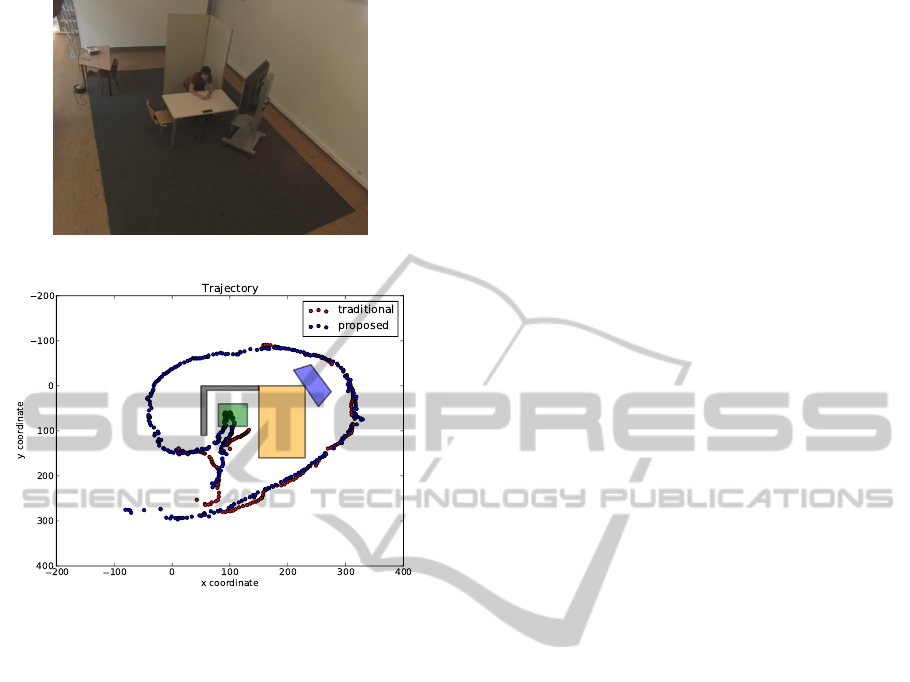
(a)
(b)
Figure 7: This figure shows the result of the trajectory of a
person that enters the room in the bottom, walks to the table
(yellow) and sits there on a chair (green), stands up from
this chair and walks around his workplace. The blue dots
represent our proposed algorithm and produce output for the
complete trajectory (even with severe occlusion due to the
table, TV screen (blue) and the wall (gray). The traditional
visual hull algorithm only outputs positions for 36.9% of the
frames. Visual inspection learns that the blue dots are much
closer to the actual person than the red dots. The camera
setup is the same as in figure 3.
can be treated as a form of occlusion.
The algorithm can handle both static and dynamic
occlusion because it operates on a frame by frame ba-
sis without temporal information of the occluders. In
future work this information could be integrated.
REFERENCES
Allied Vision Technologies. Manta G-046C. http://
www.alliedvisiontec.com/us/products/cameras/gigabit-
ethernet/manta/g-046bc.html. Accessed: 2014-09-14.
Guan, L., Sinha, S., Franco, J.-S., and Pollefeys, M. (2006).
Visual hull construction in the presence of partial
occlusion. In 3D Data Processing, Visualization,
and Transmission, Third International Symposium on,
pages 413–420. IEEE.
Laurentini, A. (1994). The visual hull concept for
silhouette-based image understanding. Pattern Anal-
ysis and Machine Intelligence, IEEE Transactions on,
16(2):150–162.
Laurentini, A. (1997). How many 2d silhouettes does it
take to reconstruct a 3d object? Computer Vision and
Image Understanding, 67(1):81–87.
Laurentini, A. (1999). The visual hull of curved objects. In
In Proceedings of ICCV99, Corfu, pages 356–361.
Ober-Gecks, A., Haenel, M., Werner, T., and Henrich, D.
(2014). Fast multi-camera reconstruction and surveil-
lance with human tracking and optimized camera con-
figurations. In ISR/Robotik 2014; 41st International
Symposium on Robotics; Proceedings of, pages 1–8.
VDE.
Slembrouck, M., Van Cauwelaert, D., Van Hamme, D.,
Van Haerenborgh, D., Van Hese, P., Veelaert, P., and
Philips, W. (2014). Self-learning voxel-based multi-
camera occlusion maps for 3d reconstruction. In 9th
International Joint Conference on Computer Vision,
Imaging and Computer Graphics Theory and Appli-
cations (VISAPP-2014). SCITEPRESS.
St-Charles, P.-L., Bilodeau, G.-A., and Bergevin, R. (2014).
Flexible background subtraction with self-balanced
local sensitivity. In Proceedings of IEEE Workshop
on Change Detection.
Stengel, D., Wiedemann, T., and Vogel-Heuser, B. (2012).
Efficient 3d voxel reconstruction of human shape
within robotic work cells. In Mechatronics and Au-
tomation (ICMA), 2012 International Conference on,
pages 1386–1392. IEEE.
Toth, C., O’Rourke, J., and Goodman, J. (2004). Hand-
book of Discrete and Computational Geometry, Sec-
ond Edition. Discrete and Combinatorial Mathematics
Series. Taylor & Francis.
Wang, Y., Jodoin, P.-M., Porikli, F., Konrad, J., Benezeth,
Y., and Ishwar, P. (2014). Cdnet 2014: An expanded
change detection benchmark dataset. In Proceedings
of the IEEE Conference on Computer Vision and Pat-
tern Recognition Workshops, pages 387–394.
VISAPP2015-InternationalConferenceonComputerVisionTheoryandApplications
642
