
A Method for Business-IT Alignment of Legacy Systems
Jonathan Pepin
1,2
, Pascal André
1
, Christian Attiogbé
1
and Erwan Breton
2
1
AeLoS Team, LINA CNRS UMR 6241, University of Nantes, Nantes, France
2
Mia-Software, Nantes, France
Keywords:
Enterprise Architecture, Information Systems, Alignment, Model Transformation, Legacy Code, Tools.
Abstract:
The separate evolution of the business side of the information system and its IT side leads to inconsistent
enterprise architectures. The consequences are unpredictable and costly evolutions of software systems, de-
layed answers to strategic decisions requirements. Numerous contributions emerged to answer the Business-IT
alignment problem but they do not completely fit to legacy systems because either they are top-down or they
focus on the strategic alignment or they require seamless models like the BPM-SOA alignment. We propose a
method to tackle the challenge of legacy architectures alignment from a practical point of view. This method
includes: (i) meta-models (business process, functional and application), (ii) a top-down and bottom-up pro-
cess to feed the models and (iii) an implemented tool chain based on model transformations and weaving. Our
objective is to establish and maintain a consistency link between the legacy software architecture models and
the enterprise business models. This link makes them aligned and the mismatches can be revealed (as-is) and
avoided in the future state of the system (to-be). We experiment the method on a real case study.
1 INTRODUCTION
Organisations face the crucial challenge to react
quickly to their environment changes, i.e. to respond
to the market competition, to respect new law obliga-
tions, to improve the return on invest or the business
quality. Applying the strategic decisions that grasp
these challenges, implies to control the whole busi-
ness organisation and its underlying Information Sys-
tem (IS). In particular, it is necessary to measure the
impact of the decisions on the IS evolution. The dis-
cipline to steer the evolution of IS is Enterprise Archi-
tecture (EA) (Lankhorst, 2013) and its representation
describes the current state of a business (as-is) and a
desired state of a business (to-be) (Clark et al., 2012).
An Information System is perceived by its stake-
holders according to two viewpoints: Information
Technology (IT) and Business. Both viewpoint in-
clude strategic (scope, governance, competences) and
operational elements (architectures, processes and
skills) (Henderson and Venkatraman, 1993). Busi-
ness and IT co-evolve in the enterprise according to
strategic decisions or operational constraints. Keep-
ing Business and IT consistent is of prime concern
to achieve essential business objectives. Business-
IT and architecture alignment are EA subjects that
address these issues (Henderson and Venkatraman,
1993; Ullah and Lai, 2013).
Maintaining legacy systems, i.e. the current state
of the IT, besides new architectures or new business
rules, is a mandatory but costly activity. Our mo-
tivation is to help decision makers to capture the
alignment of legacy systems with the related busi-
ness models in order to underline the cross effects of
IT or business evolutions. Numerous contributions
emerged to answer the Business-IT alignment prob-
lem but alignment of legacy systems remains an on-
going concern (Chan and Reich, 2007; Clark et al.,
2012). Our objective is to establish and maintain a
tight link between the applications of the legacy sys-
tem and the business models of the enterprise. This
link makes them aligned and the mismatches can be
revealed (as-is) and avoided in the future state of the
system (to-be). This is an operational approach.
We propose a method to tackle the alignment of
legacy systems in a pragmatic way. It consists in
gradually (i) building models from the business side,
(ii) extracting models from the IT side and (iii) re-
lating the models consistently. Our alignment pro-
cess is two-way: a bottom-up approach computes the
architectural model from the IT applications and a
top-down approach establishes the business process
model. At the meeting point, the effective align-
ment is a concrete mapping between models. Our
method focuses on the functional integration of the
alignment (Henderson and Venkatraman, 1993), the
229
Pepin J., André P., Attiogbe C. and Breton E..
A Method for Business-IT Alignment of Legacy Systems.
DOI: 10.5220/0005351502290237
In Proceedings of the 17th International Conference on Enterprise Information Systems (ICEIS-2015), pages 229-237
ISBN: 978-989-758-098-7
Copyright
c
2015 SCITEPRESS (Science and Technology Publications, Lda.)
strategic aspects are not considered here.
We propose EA meta-models at different abstrac-
tion layers (application, functional and business pro-
cess). The meta-model ontologies are inspired by the
main EA frameworks and we designed meta-model
inter-relationships in order to support alignment. In
legacy systems, there must be a way to feed the mod-
els by mining the existing information sources (code,
models, documents). EA proposes principles and
guidelines to achieve viewpoint alignment but prac-
titioners require a tool chain that helps to build an
alignment. Our method is equipped with models and
weaving transformations to mechanize the tool chain.
The article is structured as follows. Section 2 in-
troduces the context of the work whereas Section 3
overviews our method. In Section 4 we overview the
proposed meta-models. Section 5 is devoted to the
two-way process and details the different technolo-
gies to establish inter-model relationships. Section 6
illustrates our method and its tool support on a Mutual
Insurance company case study, showing the method
applicability. We introduce metrics to evaluate the
concrete mapping. Last, Section 7 concludes the arti-
cle and draws some perspectives.
2 BUSINESS-IT ALIGNMENT
According to Campbell, "Alignment is the business
and IT working together to reach a common goal."
as quoted by Chan et al. (Chan and Reich, 2007).
No standard definitions exist because alignment cov-
ers numerous dimensions (people, culture, organisa-
tion, relation, quality...) (Ullah and Lai, 2013). As an
example, the GRAAL method (Lankhorst, 2013) dis-
tinguishes a three dimensional world: the social di-
mension (the world of business), the physical dimen-
sion (the world of computers and networks) and the
symbolic dimension (the world of software applica-
tions). To achieve an alignment, the GRAAL method
suggests different approaches. The alignment of the
software with people requires a meaningful matching
between the software interface symbols and their un-
derstanding by the involved people. The alignment
of software with the business processes requires to
align the services provided by the software with the
services required by the processes. Our work mainly
focuses on this last approach.
Enterprise Architecture (EA) (Lankhorst, 2013)
provides adequate frameworks to identify the
Business-IT alignment issue. EA blueprints denote
the abstraction layers captured by an architectural vi-
sion. In the EA context the alignment targets the con-
cepts to be linked between the selected layers. Com-
mon EA representations mix viewpoints and layer-
ing in a single frame where the business viewpoint
drives the high-level layers and the IT viewpoint is
concerned with the low-level layers. As an example,
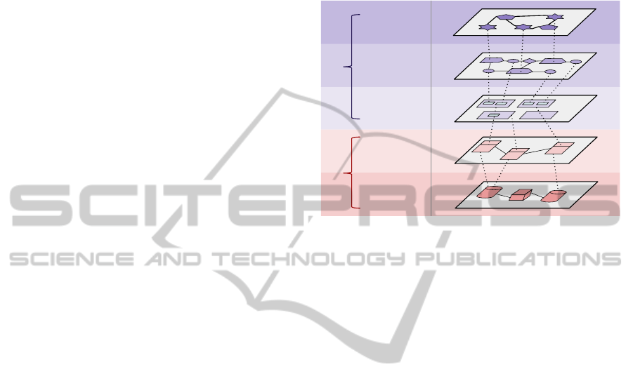
Figure 1 illustrates a five-layers stack of models.
Strategy
Layer
Business
Process Layer
Infrastructure
Layer
Functional
Layer
Application
Layer
Business
IT
Figure 1: Information System layers and an ideal alignment.
Strategic. The strategic layer is the positioning of
the enterprise: its organisational goals and success
factors, products/services, targeted market.
Business Process. The business process layer refers
to the organisation structure represented by pro-
cess, activity and actors.
Functional. This layer organises the functionalities
from business services in nested blocks called
Zone, District and Plot (Longépé, 2003).
Application. The application layer is used to model
software components and services with their in-
terrelationships.
Technical. The infrastructure layer represents all re-
sources for the storage, communication and exe-
cution; for instance database, servers, networks.
The dashed lines between the layers represent an
"ideal" alignment where the low-level IT concepts are
aligned to high-level business concepts. It is qualified
as "ideal" because alignment is not simply the mat-
ter of abstraction (e.g. traceability). Moreover, busi-
ness concepts are not fully comparable with IT con-
cepts. The nature of the links established for an align-
ment differ according to the considered works. In TO-
GAF (The Open Group, 2011) and ArchiMate (The
Open Group, 2013), the link is defined from busi-
ness services to application services. In many other
works (DISIC, 2012; Saat et al., 2010) the links are
described between Activity (or Task) and Application
Service. In practice, we have to adapt and instantiate
these general conceptual frameworks.
Several related approaches focus on the very high-
level, as mentioned in (Wieringa et al., 2003) or
ICEIS2015-17thInternationalConferenceonEnterpriseInformationSystems
230
(Schief et al., 2012). These approaches are not
equipped with tools. Other proposals are bound
to specific EA frameworks, e.g. BPM/SOA (Choi
et al., 2013; De Castro et al., 2011) or a specific
method or framework e.g. LEAP (Clark et al., 2012),
SEAM (Wegmann et al., 2007), Archimate (Fritscher
and Pigneur, 2011) or the Service-Oriented Strate-
gic Alignment Model (SOSAM) (Cuenca et al., 2014)
where the alignment definition is built around the ser-
vice paradigm. Due to the semantic proximity, the
business (process) model matches with the IT (ser-
vice) architecture but the assumption is strong since
few legacy systems are service oriented. We found
few related approaches take into account legacy sys-
tems. Hunold et al. use patterns to extract archi-
tectural information in order to re-engineer legacy
applications (Hunold et al., 2009) but alignment is
missing. EA languages are currently exclusively top-
down (Clark et al., 2012), which excludes legacy sys-
tems. Clark et al. promote a synthetic approach
but it is not related to legacy systems. Wieringa et
al. (Wieringa et al., 2003) propose an analytic frame-
work to application architecture design, given a busi-
ness context and an operational framework but no tool
support was mentioned.
A perfect alignment is never reached because the
IS is subject to many factors of changes e.g. technol-
ogy or laws evolution (Luftman et al., 1999). Also,
a visual representation of the alignment problem is
sometimes confusing: the one of Figure 1 suggests
that we have the same concepts at different abstrac-
tion levels. However IT and business domains are
not comparable since there are no architectural mod-
els that include both viewpoints but rather a mapping
as depicted by the Figure 2.
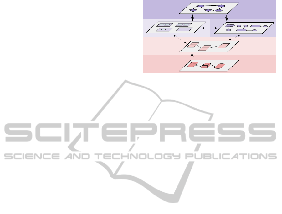
3 OVERVIEW OF THE METHOD
The alignment method includes: the definition of the
layers, the alignment model and an assisted process to
fill the models and compute a mapping. Figure 2 illus-
trates our pragmatic approach: alignment is a conver-
gence of both the business and the IT points of view.
We refine the business strategy by modelling and we
abstract the IT support by reverse engineering.
EA Meta-models. Our EA framework definition is
a variant of the reference stack of Figure 1 with the
following assumptions on the inputs: the legacy code
stands for the infrastructure layer and a collection
of documents stands for the strategy layer. We fo-
cus on the meta-models of the three intermediate lay-
ers: BPM stands for the Business Process Model, Fun
Reverse engineering
Concrete mapping
Modeling
App
Fun
BPM
Figure 2: Our approach alignment of IS layers.
stands for the Functional meta-model and App stands
for the Application meta-model. They are the core
models of the concrete mapping, as illustrated by Fig-
ure 2. The definitions of the generic meta-models are
detailed in Section 4.
Model Alignment Process. Whatever models are
chosen, a major concern is to handle their interoper-
ability. Aligning is to establish the relationships be-
tween the layer’s models. The reference stack model
of Figure 1 hides the heterogeneous EA practice ma-
turity of enterprises: designing detailed business pro-
cesses is more difficult than modeling macro-level
functionalities. Many enterprises borrow only one
representation, either Business Process or Functional.
Consequently, in Section 5 we propose a pairwise re-
lationship between the three central layers of Figure 2
instead of the "ideal" alignment of Figure 1. The
alignment process is detailed in Section 6.
Tool Chain. Our method is guided by practical con-
cerns: tools must drive the alignment. First, a bottom-
up abstraction, supported by reverse engineering tech-
niques, builds the App model from the source code.
This step by step process is detailed in Section 6.
Second, following a top-down approach, the business
strategy information is analysed to build the BPM and
the Fun models (see Section 6). The business ana-
lysts and the enterprise architects draw up these mod-
els by exploiting their knowledge about the enterprise
organisation and activities. Third, the core alignment
is implemented by a concrete mapping between these
models according to the principles established in Sec-
tion 5 and illustrated in Section 6.
4 META-MODELS FOR EA
Defining ontologies is often cumbersome. The three
meta-models we define are a compromise between ex-
pressivity, genericity and simplicity. These qualities
AMethodforBusiness-ITAlignmentofLegacySystems
231
enable one to apply the method to a broad diversity of
applications but also to support large and complex IT
systems. We define three core meta-models and in-
terrelationships (Section 5) in order to achieve align-
ment. The business and functional models must be
convenient to any enterprise organisation. The appli-
cation model must be generic to capture the software
concepts of various programming styles.
A Generic Business Process Meta-model. A Busi-
ness Process is a collection of activities that take one
or more inputs and create output values (Hammer
and Champy, 2006). Our aim is to define a sim-
ple and generic meta-model compatible with com-
mon notations which describe business processes:
BPMN, UML activity, and other OMG standards. A
Process can be triggered by another process through
a Transition. Processes are performed by Roles
that define a behaviour played by one or more Actor
(human, software or hardware). A process may
be structured in a set of Sub-process and can be
grouped in Partition or Sub-Partition. Further-
more, a process is composed of Activities which
is a set of Task that operates DataObject. The se-
quence of transitions is triggered by Event (begin, in-
termediate or end) which generates a chain reaction in
the process controlled by Condition.
A Generic Functional Meta-model. A functional
model is a division of the Information System in func-
tional blocks. This representation is inspired by the
City Planning metaphor: the IS is comparable to a city
which is composed of areas, services and exchanges.
This city is subject to transformations and optimiza-
tions depending on the needs and the growth. A gran-
ularity level is defined by subBlock inside Block.
The common decoupling hierarchy is Zone, District
and Plot (Longépé, 2003). Each block can handle
DataObject and manipulates Functionality.
A Generic Application Meta-model. An applica-
tion model depicts an abstract view of the applica-
tions of the IT infrastructure layer in the spirit of
the works on software architecture, including compo-
nent and service models. An Application is com-
posed of Components which are reusable and replace-
able elements providing Functions. A component is
accessible by its Interface. component functions
are exposed through Services and supply compu-
tations. We compare our App meta-model with the
original Archimate meta-model and two meta-models
from SOA technologies (Service Component Archi-
tecture (SCA) and Web Services Description Lan-
guage (WSDL) 2.0).
The three meta-models for EA are implemented
using the Eclipse Modeling Framework (EMF)
1
in or-
der to provide method and user-friendly tools required
by for EA stakeholders and by users from the business
world or from IT world.
5 THE CORE OF THE
ALIGNMENT PROCESS
The three meta-models are linked to perform an oper-
ational model alignment. Technical details to imple-
ment the model composition are discussed.
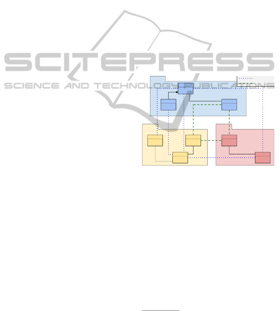
EA Models Relationships
Figure 3 summarises the relationships between the
business process, functional and application models.
We have two kinds of links: processing and data links.
Activity
DataObjectTask
Application DataObject
Service
DataObject
Functionality
BPM
App
Fun
divisionOf 0..*
0..*
dividedInto
0..* handledBy
handles 0..*
0..*
accesses
0..* accessedBy
0..*
manipulates
manipulatedBy 0..*
0..*
implementedBy
0..*
implementedBy
0..*
implements
implements 0..*
0..*
implementedBy
0..*
implements
implements 0..* 0..* realizes
0..*
realizedBy
processing link
data link
implements 0..*
implements
0..*
0..*
implementedBy
0..*
implementedBy
0..* represents
0..* representedBy
0..*
implementedBy
0..*
providedBy
provides 0..*
Figure 3: EA Meta-model Inter-relationship.
Processing Link. Each link maps one concept of
one layer to another concept of a different layer. We
use the following definitions:
• Applications support the execution of cer-
tain activities (functionalities) of business pro-
cesses (Braun and Winter, 2005).
• Application services can be used by business be-
haviour whereas application interfaces are used
by business actor roles, i.e., there is a support re-
lation between the application and business layers
(Lankhorst, 2013).
The Service of the application layer App is linked
to the Activity from business process layer BPM and
to the Functionality of the functional layer Fun.
We add a third link between Service App and Task
BPM because a fine granularity modeling uses tasks
1
http://www.eclipse.org/emf/
ICEIS2015-17thInternationalConferenceonEnterpriseInformationSystems
232

to detail the activities. For an application model with
few details and without services, one can just link
Application App to Activity BPM. Following the
above definitions, Functionality Fun is linked to
Activity BPM.
Data Link. All our generic EA meta-models have
a DataObject concept; then three links are made be-
tween the three meta-models.
Techniques for EA Mapping
In Model–Driven Engineering (MDE), model
transformations enable to implement model map-
pings: composition, merging, weaving, extension,
etc (Clavreul, 2011). In EA, Chen et al. used
repositories to link existing data sources (Chen
et al., 2013). We study four different approaches:
extension, merging, weaving and annotation. In
the first approach, the meta-model of one layer is
extended with the concepts of another. In the second
approach, the meta-models are merged in a single
big model. In both case, the meta-model loose their
consistency and moreover they can hardly evolve
(lost of flexibility). Consequently we selected and
experimented the last two methods: model weaving
and annotation.
Model Weaving. The model weaving technique is
the most flexible and non-intrusive one. Model weav-
ing specifies the links, and their associated seman-
tics, between elements of sources and targets of two
or more models or meta-models. Model weaving in-
volves the creation of an independent model which
refers to the models to weave and the links between
the considered model concepts. Weaving approaches
are already experimented and developed in Eclipse
Plug-ins with EMF technologies e.g., Atlas Model
Weaver (AMW) and Virtual EMF. AMW includes a
transformation mechanism with ATL
2
to create an au-
tomatic weaving. Virtual EMF provides a visual as-
sistant to edit two models from different meta-model
and to create links between concepts with a drag
and drop. Unfortunately, editors are no longer sup-
ported on recent Eclipse 4 versions. We build our own
models weaving assistant editor based on the existing
tools, adding some improvements and new features.
It enables one to weave more than two models. Our
editor interface has two main parts: the left part con-
tains a tree-like view of the links created by weaving
and the right part shows the different loaded models
group by meta-model. A search box helps to browse
2
Open source language and engine transformation
http:// www.eclipse.org/atl/
quickly the concepts, especially for voluminous mod-
els. The editor is still limited: the created links have
yet no conceptual meaning, they are generic and can
store any kind of concept. To solve this problem we
designed a constraint mechanism with concepts weav-
ing at the meta-model level. For example, by loading
Application and BPMN2 meta-models, we can cre-
ate a specific link like ApplicationService2Task. Dur-
ing a manual weaving, this solution allows the user
to achieve a structural validation in order to correct
errors.
Model Annotation. Mia-Software
3
developped
a small meta-model called MAnnotation in-
spired by Eannotation in the Ecore meta-model.
The MAnnotedElement interface provided by
MAnnotation can be extended by any class from
another meta-model. Each MAnnotedElement have
one or more MAnnotation, and each annotation
can have several MTag. An annotation has attributes
and links including the association references for
coupling the MannotedElement with another Object
from any loaded model.
This mechanism allows one to describe align-
ment between our EA meta-models. To experiment
with it, we extended classes of BPM, App and Fun
meta-models to the MAnnotedElement. At once, we
can reference objects in our instance of EA meta-
models. Creating annotation is very simple and the
native EMF proxy resolver is compatible, therefore it
is possible to navigate through different models by the
MAnnotation. We implemented conformance rules,
in order to prevent meaningless annotations, into the
EMF editor i.e. which concept can be linked to each
concept.
6 EA ALIGNMENT METHOD
ILLUSTRATED
The experimentation is led on a real case study pro-
vided by a French Mutual Insurance company (MIc)
which is deployed on the Information System of the
company. Business processes and the legacy source
code are provided.
Business. Despite the availability of a MEGA En-
terprise Architecture
4
model of the business, we
only got access to a HTML web portal, includ-
ing the exported image of the diagrams. In this
case, all diagrams are kind of business processes,
there is no functional representation. This is a
3
http://www.mia-software.com/
4
http://www.mega.com/en/solution/enterprise-architecture
AMethodforBusiness-ITAlignmentofLegacySystems
233
significant example of cultural diversity in busi-
ness enterprise modeling. We applied manual and
automatic transformations to fill our generic BPM
model.
IT. The MIc case study is a complete source code
written in Java. The input source code is large:
33,400 classes, about 3,400,000 code lines. A
side-effect of the study was to evaluate the capa-
bility to handle large-scale systems.
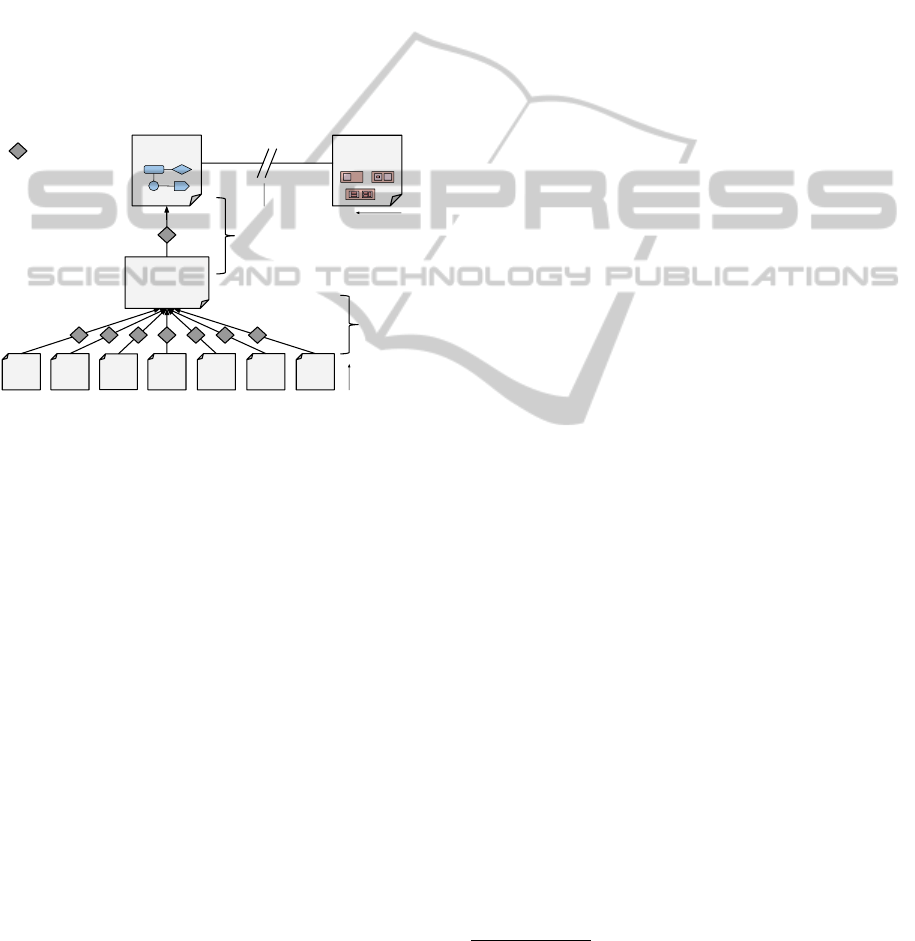
Figure 4 shows the involved models and transforma-
tions performed during three main steps: (S1) build-
ing an application model by transformation, (S2) ex-
ploiting business strategy refinement and (S3) con-
crete mapping.
KDM
model
Java
C++
Smalltalk
Cobol
WSDL
S1.2
Intermediate
Transformation
S1.1
Source Code
Reverse
Engineering
S3
Concrete Mapping
S1.3
Transformation to
High-level Abstraction
.NET
BPEL
Application
model
Business Model
Functionnal or
Process
Transformation
rule
S2
Exploiting
Business Models
Figure 4: Transformation steps.
Step 1: Building an Application Model by
Transformation
The goal here is to retrieve an application model from
the source code in order to align IT with the busi-
ness. The distance between the programming lan-
guage level and the application architecture level is
too wide to be processed in a single transformation
step. Therefore the application model is produced
by a stepwise abstraction where three transforma-
tion sub-steps are necessary as depicted by the left
side of Figure 4: (S1.1) a source code reverse en-
gineering step, (S1.2) intermediate transformations
step and (S1.3) an abstraction step. According to
the Model-Driven Engineering (MDE), a Platform-
Specific Model (PSM) combines the specifications in
the PIM with the details which specify how a system
uses a particular type of platform. while a Platform
Independent Model (PIM) is a formal specification
of the structure and the function of a system that ab-
stracts away technical details.
S1.1 - Source Code Reverse Engineering. Reverse
engineering consists in analyzing the source code files
of a set of programs in order to get a representation of
the code in a model (PSM). For this purpose, reverse
engineering tools include a meta-model for each tar-
get programming language. In EA projects, the en-
vironment is heterogeneous; the reverse engineering
tool should be able to cope with several languages like
Java, C++, Smalltalk, Cobol, etc.
Ex: Java Reverse Engineering with Modisco The
program from MIc case study is written in Java.
The reverse engineering has been executed using the
Modisco
5
tool including a Java meta-model. This tool
discovers the Java model with the assistance of the
Java development tools (JDT) which parses the source
code and computes an Abstract Syntax Tree (AST).
S1.2 - Intermediate Transformation. This step
targets to produce an instance of the Knowledge
Discovery Meta-model (KDM)
6
intermediate model
(PIM). KDM includes many layers to save different
aspects of common programming languages and more
generally it defines common concepts for software as-
sets and their operational environments. We borrow
only a part of KDM, mainly the code package which
contains all the characteristics of the current program-
ming language.
Ex: Java Model to KDM Transformation Modisco
provides this transformation, but we faced the prob-
lem of scaling the size of the model. Indeed Modisco
is not dedicated to the EA alignment problem and too
much information was stored, so we had to write our
own transformation using the Mia-transformation tool.
S1.3 - Transformation to a High-level Abstraction.
The issue here is to transform the KDM model into
our App model. App preserves only the architectural
information to be aligned later with the business. It
is necessary to build an algorithm or a set of rules
to detect the different concepts from the application
meta-model. This algorithm is more or less com-
plex depending on the architecture used in the source
code. Making such an abstraction is based on the
inter-relationships described in Section 5.
Ex: The KDM to Application Transformation We
wrote a Mia-transformation to obtain an application
model containing the links between components, in-
terfaces, services, functions and data objects. The
source code of the MIc uses a specific file naming
based on name prefixing. This naming policy iden-
tifies the software architecture role of different Java
interfaces and classes. This unusual feature helps us
to create a perfect transformation in a very short time.
5
Modisco is an open source project supported by Mia-
Software. http://www.eclipse.org/MoDisco/
6
Used by the modernization community in mining tools.
http://www.omg.org/technology/kdm/
ICEIS2015-17thInternationalConferenceonEnterpriseInformationSystems
234
Related approaches exist: De Castro et al. de-
scribe a top-down approach with transformation rules
to generate a web service architecture from a business
process model in (De Castro et al., 2011); Soltani et
al. (Soltani and Benslimane, 2012) proposes an Auto-
matic Model-Driven Service Identification (AMSI) to
detect SOA services from high level business process,
they annotate the BPM to perform transformation and
generate automatically the target service. Conversely
to these works, we handle any software architecture
with any business representation.
Step 2: Exploiting Business Information
As mentioned above, designing a business process
model is a manually performed by business analysts.
Here we propose two business related models for two
different view points: functional and business pro-
cesses. If these models already exist, we can create
a transformation from the legacy models to our EA
models. When starting from scratch, our meta-models
stay good candidates thanks to their genericness.
Business Information Extraction from the MEGA
Reference. A MEGA reference exists at the MIc
company but only a static HTML export was avail-
able. All the diagrams of business process models
were saved as image files; it was then impossible to
get a model with reverse engineering; we decided to
make manual transcriptions from diagram in HTML
website to our BPM meta-model. Table 1 illustrates a
translation from the specific MEGA meta-model de-
fined for the MIc case to BPM concepts.
Table 1: The translation rules.
MIc BPM Description
Pool Partition Groups a set of structural activities
Actor Actor Function or role in the company
Message Sequence Flow Order between activities
Process Process The highest level contain all activities
Procedure Activity Activities can compound activities
Operation Task Atomic activity - the finest level
Step 3: Concrete Mapping
In the final step, the business process models resulting
from Step 2 are coupled with the application model
obtained at Step 1. We choose the most relevant com-
position method defined in Section 5 to implement the
mapping.
Business and Application Alignment. We imple-
mented the MIc case study concrete mapping us-
ing our weaving editor. We did not translate all the
MEGA diagrams: the business source for the align-
ment process was restricted to a specific functional
area called Bank Address with its business processes.
The goal of the alignment was to detect similar con-
cepts present in both the application and the business
process modelse.g. the Service concept from App
model and Task from the BPM model. We used the
search facility implemented by our weaving editor to
find naming correspondences.
Experimentation Results and Evaluation
The MIc case study enabled us to evaluate the ap-
plicability of our method on a complex and big size
legacy systems. The MIc was developed rigorously,
improving the quality of the legacy information. The
experimentation was performed on a computer with 4
cores CPU, 6 GB memory allocated to the JVM and
SSD. At Step 1, Modisco took about 10 mins to com-
pute the 1.4 GB XMI file. At Step 2, the initial ATL
transformation did not terminate. Then we obtained
a KDM model after about 2 hrs of execution with our
own Mia-Transformation rules, the file sized 780 MB.
At the last step, we executed our KDM to application
model transformation with Mia-transformation. It re-
turned a 2 MB App model, which was an abstraction
of the initial KDM model. This abstraction improves
the readability because only the pertinent information
is kept. A better degree of automation and coverage
could be reached if the source of MEGA was avail-
able because the links between Service and Operation
were already defined in the MEGA diagrams.
At the end of the process, one can detect manually
misalignments in the as-is system after the attempt to
link the concepts between the layers. The next stage
is to evaluate the quality of the alignment and to pro-
duce indicators to reveal misalignment or to measure
other properties. We defined metrics to evaluate the
alignment between concepts. We chosed the Object
Constraint Language (OCL) to implement the metric
rules because EMF has an embedded engine to exe-
cute queries. As an example, Listing 1 computes the
NAE-BAM rate i.e. the Number of Aligned Elements
between the alignable concepts of BPM and App Mod-
els.
Listing 1: OCL Rule for NAE-BAM
c o n t e x t A p p l i c a t i o n L a y e r :
app : : A p p l i c a t i o n . a l l I n s t a n c e s ( )−> s e l e c t (
m A n no t a t i o n s . f i e l d . r e f e r e n c e s . e C l a s s ( ) .
in st an ce T y p eN am e−> e x i s t s ( s | s = ’bpm . A c t i v i t y
’ ) )−> s i z e ( )
AMethodforBusiness-ITAlignmentofLegacySystems
235

+ app : : S e r v i c e . a l l I n s t a n c e s ( )−> s e l e c t ( m A nn o t a t i o ns
. f i e l d . r e f e r e n c e s . e C l a s s ( ) . in s t a n c eT yp eN a m e−>
e x i s t s ( s | s = ’bpm . A c t i v i t y ’ or s = ’bpm . Task
’ ) )−> s i z e ( )
+ app : : Da t a O b j e c t . a l l I n s t a n c e s ( )−> s e l e c t (
m A n no t a t i o n s . f i e l d . r e f e r e n c e s . e C l a s s ( ) .
in st an ce T y p eN am e−> e x i s t s ( s | s = ’bpm .
D a t a O b j e c t ’ ) )−> s i z e ( )
Other criteria have been defined to measure
alignment: coverage, consistency, coupling, confor-
mance, . . . Each criterion is supported by an analysis
rule on OCL. In the alignment link we added a weight
feature for measuring alignment based on specific cri-
teria like cost maintenance, execution time, strategic
priority, etc. These metrics help for re-factoring, re-
architecturing and improving the alignment. In this
way, we introduce the threshold notion; if given level
is exceeded a warning is thrown, appropriate actions
should be executed. We plan to implement a dash-
board with all metrics results, indicators and viola-
tions, e.g. plug-in for Sonar
7
.
7 CONCLUSION
Business-IT alignment remains an open challenge in
Information System (IS) research. Industry faces this
challenge during the maintenance and evolution of
legacy systems. We contribute in a pragmatic ap-
proach with an operational method, to bring closer
the business and the IT dimensions in order to link
both dimensions and detect mismatches. First we de-
fined two meta-models for the business domain (pro-
cess and functional) and one for the IT domain (appli-
cation) which are a data support for alignment. Sec-
ond we described a top-down and bottom-up process
to reconcile business and IT view of the IS. Last,
we fully implemented EMF model and transforma-
tions to build an abstract model from software, and
model composition (weaving or annotations) to trace
Business and IT models alignment. The applicability
of the method has been validated on real case study.
Metrics enable to measure the alignment quality.
This work is the cornerstone of a long-term project
to provide techniques and tools for IS maintenance
and evolution. The first short-term perspective is
to highlight misalignment and evaluate Business-IT
alignment using various criteria: consistency, cou-
pling, business coverage, cost maintenance, etc. We
are currently working on the formalisation and vali-
dation of our set of metrics on the alignment quality.
Besides, we have to improve the detection of candi-
date matching in our three meta-models in order to
7
http://www.sonarqube.org/
better assist the weaving designer. Language process-
ing and patterns are candidate techniques, the idea is
to define probabilistic criteria to compare model ele-
ments. We plan to compare the current alignment of
the IS with the ones of its evolution scenarios, in order
to deal with the cost of IS evolution.
Detailed information is available at http://www.lina.
sciences.univ-nantes.fr/aelos/download/iceis15_sub.pdf
REFERENCES
Braun, C. and Winter, R. (2005). A comprehensive enter-
prise architecture metamodel and its implementation
using a metamodeling platform. In Proceedings of
EMISA, volume 75 of LNI, page 64–79. GI.
Chan, Y. E. and Reich, B. H. (2007). IT alignment: what
have we learned? JIT, 22(4):297–315.
Chen, W., Hess, C., Langermeier, M., Stuelpnagel, J., and
Diefenthaler, P. (2013). Semantic enterprise architec-
ture management:. In ICEIS, pages 318–325.
Choi, J., Nazareth, D. L., and Jain, H. K. (2013). The impact
of SOA implementation on IT-Business alignment: A
system dynamics approach. ACM Trans. Manage. Inf.
Syst., 4(1):3:1–3:22.
Clark, T., Barn, B. S., and Oussena, S. (2012). A method
for enterprise architecture alignment. In Proceedings
of PRET, volume 120, pages 48–76. Springer.
Clavreul, M. (2011). Model and Metamodel Composition:
Separation of Mapping and Interpretation for Unify-
ing Existing Model Composition Techniques. PhD the-
sis, Université Rennes 1.
Cuenca, L., Boza, A., Ortiz, A., and Trienekens, J. J. M.
(2014). Business-IT alignment and service oriented
architecture - a proposal of a service-oriented strategic
alignment model:. In ICEIS, pages 490–495.
De Castro, V., Marcos, E., and Vara, J. M. (2011). Applying
CIM-to-PIM model transformations for the service-
oriented development of information systems. Inf.
Softw. Technol., 53(1):87–105.
DISIC (2012). French Government Common EA Frame-
work. (french).
Fritscher, B. and Pigneur, Y. (2011). Business IT align-
ment from business model to enterprise architecture.
In CAiSE 2011, volume 83, pages 4–15. Springer.
Hammer, M. and Champy, J. (2006). Reengineering the
Corporation: A Manifesto for Business Revolution.
HarperBusiness, New York.
Henderson, J. C. and Venkatraman, N. (1993). Strate-
gic alignment: Leveraging information technology for
transforming organizations. IBM Syst. J., 32(1):4–16.
Hunold, S., Krellner, B., Rauber, T., Reichel, T., and
Rünger, G. (2009). Pattern-based refactoring of legacy
software systems. In ICEIS, pages 78–89. Springer.
Lankhorst, M. M. (2013). Enterprise Architecture at Work -
Modelling, Communication and Analysis (3. ed.). The
Enterprise Engineering Series. Springer.
ICEIS2015-17thInternationalConferenceonEnterpriseInformationSystems
236

Longépé, C. (2003). The Enterprise Architecture IT
Project: The Urbanisation Paradigm. Elsevier.
Luftman, J., Papp, R., and Brier, T. (1999). Enablers and
inhibitors of business-IT alignment. Commun. AIS.
Saat, J., Franke, U., Lagerstrom, R., and Ekstedt, M. (2010).
Enterprise architecture meta models for IT/Business
alignment situations. In EDOC, pages 14–23.
Schief, M., Bonakdar, A., and Weiblen, T. (2012). Trans-
forming software business models into business pro-
cesses. In ICEIS 2012 Proceedings, pages 167–172.
Soltani, M. and Benslimane, S. M. (2012). From a high
level business process model to service model artifacts
- a model-driven approach:. In ICEIS, pages 265–268.
The Open Group (2011). TOGAF Version 9.1. van Haren
Publishing, 10th edition.
The Open Group (2013). Archimate 2.1 Specification. Van
Haren Pub.
Ullah, A. and Lai, R. (2013). A systematic review of busi-
ness and information technology alignment. ACM
Trans. Manage. Inf. Syst., 4(1):4:1–4:30.
Wegmann, A., Regev, G., Rychkova, I., Le, L.-S., and Julia,
P. (2007). Business and it alignment with seam for
enterprise architecture. In EDOC, pages 111–121.
Wieringa, R., Blanken, H., Fokkinga, M., and Grefen, P.
(2003). Aligning application architecture to the busi-
ness context. In Eder, J. and Missikoff, M., editors,
CAiSE, pages 209–225. Springer-Verlag.
AMethodforBusiness-ITAlignmentofLegacySystems
237
