
Simulation and Implementation of a Poly Methyl Methacrylate based
Whispering Gallery Mode Ring Resonator in Microwave Range
A. Malekpour, A. Rostami, M. Sarmadi, M. Dolatyari and G. Rostami
OIC Research Group, School of Engineering-Emerging Technologies, University of Tabriz, Tabriz 5166614761, Iran
Keywords: Ring Resonator, Poly Methyl Methacrylate (PMMA), Whispering Gallery Mode, Microwave Frequency.
Abstract: This article introduces the ring resonator sensing principle and presents the simulation and fabrication of a
ring resonator structure. The material Poly methyl methacrylate (PMMA) with refractive index of 1.5 has
been used for fabricating it. It has low loss and thereby is a good material for constructing low loss ring
resonators and generating high Q-factors. 3-D finite element numerical method (FEM) simulation results
show the path of light through ring resonator and the transmission parameter of a waveguide in close proximity
of a ring resonator. After coupling electromagnetic wave from the waveguide into the ring resonator, the
standing waves are formed as resonant optical modes. Subsequently resonance peaks are formed in
periodically repetitive frequencies in the transmission parameter of the waveguide. Transmission spectrum of
waveguide has been studied in the frequency range 8-8.3 GHz. Ring resonator parameters like free spectral
range and quality factor have been calculated by 0.1245 GHz and 200 respectively. Agreement and differences
between simulation and experiment have been discussed.
1 INTRODUCTION
Whispering gallery modes (WGMs) are specific
resonances of a wave field, inside a given resonator
or a cavity with smooth edges. The resonators have
axially symmetric geometry such as sphere, disk or
ring. WGMs can be described as propagating modes
circling around the resonator, supported by
continuous total internal reflection of the resonator or
cavity surface, that meet the resonance condition.
This means that after one round trip they return to the
same point with the same phase shift of integer
multiples of 2π. Hence the waves interfere
constructively with themselves, and form standing
waves.
The operating principle in ring resonator based
sensors is mainely based on resonance perturbation
method, where a sample under test perturbed the
effective refractive index of the resonator (Zhu,
Hongying, 2007, Delâg, 2009). Resonance field
perturbes by the refractive index changes and causes
a change in the resonance frequency and Q-factor.
Other perturbation in resonance frequency is caused
by the attachment of a desirable particle (Ahmadi,
2014). These changes can be calibrated to represent
the sensing parameters of interest. This is an example
of RI sensors that involves detecting the spectral shift
of a resonance feature as the RI varied. The other
approaches of such RI sensors are valid and have a
wide range of applications in areas such as life
science (Yu. Zongfu, 2011). Yet the most interesting
from a practical viewpoint about electromagnetic
WGMs, is that they posses many unique properties,
such as ultra-high Q-factors, having low mode
volumes and operating at optical and
telecommunication frequencies of light. So WGM is
one of the most accurate and sensitive techniques
proposed to date for sensing applications due to its
sensitivity and selectivity.
High unloaded Q-factor is mainely limited by the
loss tangent of the resonator material for highly
confined modes. Hence chossing very low loss
materials such as poly methyl methacrylate (PMMA)
is of paramount importance. Depending on where the
sensing signal originates, there are two types of
sensing that a ring resonator can accomplish. The
sample under test in close proximity to the ring
resonator surface (much closer that the evanescent
field decays length) performs the surface sensing
signal. Whereas bulk sensing signals comes from the
optical change induced by the presence of the sample
in the whole region of the evanescent field. Placing
and removing the sample at predetermined location
108
Malekpour A., Rostami A., Sarmadi M., Dolatyari M. and Rostami G..
Simulation and Implementation of a Poly Methyl Methacrylate based Whispering Gallery Mode Ring Resonator in Microwave Range.
DOI: 10.5220/0005335901080112
In Proceedings of the 3rd International Conference on Photonics, Optics and Laser Technology (PHOTOPTICS-2015), pages 108-112
ISBN: 978-989-758-093-2
Copyright
c
2015 SCITEPRESS (Science and Technology Publications, Lda.)

close to the resonator, is very easy due to open
structure of a WGM structure, unlike metallic cavity.
In addition, at microwave range of the
electromagnetic spectrum, whispering gallery
resonators have relatively large dimensions and
therefore, they are easy to handle and manipulate. By
this idea, the structure becomes suitable fore mass
production, because the time consuming part of
manual adjustment is eliminated.
In this paper we have presented the simulation
results and the fabricated ring resonator structure
using PMMA that creates peak resonances in
microwave range. PMMA is considered one of the
best materials to exhibits the lowest loss. Hence high
unloaded Q-factor can be achieved. The gap between
waveguide and resonator is an important factor for the
ring resonator. Since the field distribution is weak in
the middle hole at microwave range, it is not sensitive
sensor if the sample filled the core of the ring
resonator. Placing the sample in the vicinity of the
outer rim of the resonator is not possible, because
there is no limitation for the liquid to remain in the
vicinity. For having got a good perforemance sensor,
it's a good idea to implement a groove at the ring's
surface and near the outer rim of the resonator. This
idea is practical and in the future we will have done
it.
2 THEORY AND FORMULATION
It is known from the waveguide-based optics that
occurring total internal reflection on the border of
core and clad is the basically condition for generating
waveguide structures (Taya. Sofyan, 2014). The
reflected waves interfere constructively with each
other and the modes are formed and propagated in the
waveguide. So the larger RI of the core than the RI of
the clad is an essential condition for confinement of
the wave in the core and formation of the propagating
modes in waveguides.
Waveguide cut-off frequency depends on the
effective RI and the dimensions of the waveguide.
Unlike the slab waveguides, in the rectangular
waveguides, there is no precise formula for wave
propagation in the waveguide. After a simple and
meaningful approximation, has been performed on
the solving Maxwell's equations in rectangular
waveguides, formulas have been obtained and tables
have been presented for a rectangular waveguide
(Marcatili, Enrique, 1969). So the correct dimensions
for a waveguide with predetermined RI are obtained.
It is seen that, by keeping the effective refractive
index constant, as the dimensions become larger, the
cut-off frequency of the waveguide shift to lower
frequencies. The dimensions of the waveguide are
about the wavelength of the propagating mode in that.
So for getting a waveguide at frequency 8GHz the
waveguide dimensions are in the range of centimetre
(cm), because wavelength at this range is about 3 cm.
This is also the case for ring resonator. If the ring
resonator is considered as the curved waveguide,
wave propagation in it, is the same as for the straight
waveguide. The difference between them is that there
are losses due to curved boundaries in ring resonator.
The resonance modes are in the wavelength λ, which
is given by (Sun, Yuze, 2011):
2/
reff
rn m
(1)
Where r is the resonator rim,
eff
n
is the effective RI
experienced by the optical resonant mode, and m is
an integer number. One important parameter is the
distance between resonance peaks, which is called the
free spectral range (FSR). The relation between the
FSR and the radius of the ring resonator and effective
RI is given by (Rabus. Dominik G, 2007):
2
2
r
eff
FS R
rn
(2)
It can be seen that the FSR have a direct relationship
with square of the wavenumber and an inverse
relationship with the effective RI and the radius of the
ring resonator. So it is expected that if the structure is
at microwave range the FSR would decrease by
decreasing the wavelength.
Achieving a narrowness of the resonance dip in
figure 1 is an important issue in the sensor
applications of ring resonator. The parameter of
importance is the resonance width at half maximum
or 3 dB bandwidth
r
of the resonance lineshape.
The narrowness of linewidth
r
is characterized by
the resonator's quality factor. This parameter is a
measure of the sharpness of the resonance. It is
defined as the ratio of the operation wavelength and
the resonance width:
/
rr
Q
(3)
Not too surprisingly, Q can be shown to be
proportional to the number of round trips that
circulating resonant light can make along the ring
resonator. The quality factor can also be regarded as
the stored energy divided by the power lost per optical
cycle. As the detection of the ring resonator based
sensors limit is set by how well one can locate
resonance frequency, the sharpness is important and
SimulationandImplementationofaPolyMethylMethacrylatebasedWhisperingGalleryModeRingResonatorin
MicrowaveRange
109
a high Q is essential.
Figure 1: Exhibition of the linewidth in a resonance
frequency for calculating the quality factor. .
3 DESIGN AND SIMULATION OF
THE STRUCTURE
The top view of the structure that consists of a PMMA
waveguide and a PMMA resonator is shown in Figure
2. The ring and the waveguide have the same height
1.5 cm. The cross sectional dimensions of the
waveguide are chosen to be 1.5 cm by 3.2 cm to excite
the fundamental mode
11
y
E
.
The inner and outer radiuses of the ring are 15 cm
and 24 cm respectively. The gap is chosen to be zero
in simulation and also in the experimental test to have
a good coupling at 8-8.3 GHz. In addition here a
groove is implemented in the surface of the ring for
sensing applications of the structure that we will have
in the future works. It is considerable that this groove
has effects on the resonance frequency. So resonance
frequencies are different from the situation that there
is no groove on the ring's surface. In order to keeping
up the agreement between simulation and fabrication
a groove has been added to the ring's surface in the
simulation. Having accurate measurement and
characterization, we need standard ports. So the two
ends of the PMMA waveguide are tapered and
inserted in WR-112, standard rectangular metallic
waveguide at 7.05-10.0 GHz band.
The entire structure is simulated in CST
MICROWAVE Studio 12.0, a finite element solver,
to solve for the electric field distribution and the
transmission parameter of the ring resonator
structure. The simulated distribution of electric field
in the waveguide and resonator are shown in Figure
3.
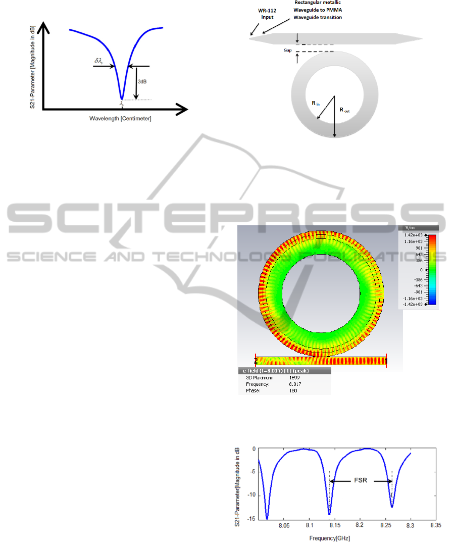
The transmission parameter of the structure which
is shown in figure 4 shows that the transmission from
one side to another of the waveguide is good, except
for the frequencies that are the resonance frequency
of ring resonator. It shows that the FSR of the ring
Figure 2: The top view of waveguide and ring resonator
structure.
resonator is about 0.13 GHz and the Q-factors are
about 1100 for resonance peaks and they are a bit
different for each resonance peak.
Figure 3: Distribution of absolute electric field over the
PMMA ring resonator beside the PMMA waveguide at
resonance frequency 8.017.
Figure 4: Transmission parameter of the PMMA structure
in the simulation.
4 FABRICATION
Despite of the previous ring resonator structures
PHOTOPTICS2015-InternationalConferenceonPhotonics,OpticsandLaserTechnology
110
dimensions, the present case here, have centimetre
dimensions. So fabricating of it, is easy, practical and
affordable, and has no time consuming. There is no
need for complicated technologies like the dark room
or photolithography for fabrication. A PMMA slab
with 1.5 cm height has been cut by laser such that a
waveguide and a ring have been created. The vertical
and horizontal cuttings of the two tapered ends of the
waveguide are done by the former way and computer
numerical control (CNC) milling machine
respectively. Since both the waveguide and the ring
has not the precise above mentioned dimensions (in
section 3), they machined by CNC milling machine
to have accurate dimensions in the implemented
structure exactly equal to that dimensions presented
by the simulation. The groove on the surface of the
ring is cut by machinery mechanic too. The next
problem when implementing such kind of structures
was fixing them to have a correct gap between the
ring and the waveguide. Connecting the waveguide
ends to the ports needs fixing too. Having centimetre
dimensions this problems have been solved by
themselves. The PMMA ring resonator is placed
close to the PMMA waveguide by manual
adjustment. Centimetre geometries both in the ports
and in the tapered ends as a coupler, we connect them
to each other by manual adjustment too. Figure 5
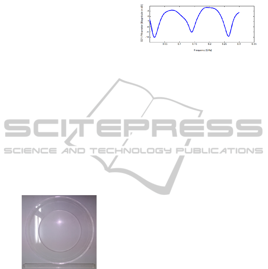
shows the final device after fabricating it.
Figure 5: The fabricated PMMA waveguide and PMMA
ring resonator.
5 EXPERIMENTAL SETUP
The source wave at 8-8.3 GHz is provided by 85107A
network analyzer. It has plotted the transmission
parameter which is shown in figure 6 in order to
calculating the ring resonator parameters, FSR and Q.
It should be mentioned that the FSR can be attributed
to the refractive index and loss of the PMMA. The
matching between simulation and experimental
transmission parameter is achieved.
Figure 6: The plotted transmission Parameter of the ring
resonator structure in the implementation.
It shows that the FSR of the ring resonator in the
experiment is about 0.12 GHz and the Q-factors are
about 200 and they are a bit different for each
resonance peak.
The resonance frequencies are approximately the
same as for the simulation. As it is visible from the
comparison between simulation and fabrication there
is a drop in the resonator response between
resonances of the implemented structure. This is
because of the attenuation that occurred by the two
tapered ends, and it is unavoidable. The tapered ends
are essential to have a good impedance matching
between the waveguide and the ports. This impedance
matching is frequency dependence of course, but the
dependency could be ignored in a small frequency
band such as 8-8.3 GHz. If this frequency band
became larger, the variant impedance matching
respect to the frequency would be visible. The other
reason for the attenuation in the fabricated structure
is the trivial PMMA electrical conductivity that has
been assumed zero in simulation and here creates an
offset in the waveguide's transmission.
The other difference which is visible in the
experimental results in comparison with the
simulation is lower quality factor and is due to the
attenuation caused by the PMMA electrical
conductivity in the ring resonator. Since we expect
that Q decrease by the attenuation enhancement in the
ring resonator, it is more likely that the groove
geometry affects that resonator transmission function.
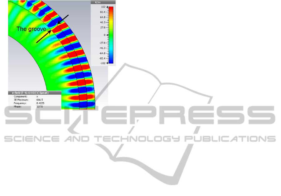
This could be seen more obviously in figure 7. By
punctuality it is seen that electromagnetic wave has
some breaks in the border of PMMA and groove, but
they are tolerable for the wave and the propagation
don't perturbed by them. These breaks are the other
reason which is beneficial for explaining the
decreasing of the quality factor. The electromagnetic
waves tolerate the RI differences between the groove
(free space RI) and PMMA. The photon recirculation
limits by this groove and this means a slaked quality
factor. In implemented structure these breaks are
accompanied by the electrical conductivity of the
PMMA which is assumed to be zero in simulation.
SimulationandImplementationofaPolyMethylMethacrylatebasedWhisperingGalleryModeRingResonatorin
MicrowaveRange
111
Because of that the quality factors are more slaked in
the fabrication.
Figure 7: simulated 3D electric field (x component)
distribution of the ring resonator with a groove on the
surface. The electromagnetic waves break when they meet
the groove.
As it can be seen from the comparison, the FSR in the
experiment is lower than the simulation. This rises
from a trivial difference that we have in the PMMA
refractive index. Also the RI of the air in the reality is
more than 1 (the assumed RI for the air in simulation).
This causes that the effective RI that resonant mode
in the ring experience become larger. Since FSR have
an inverse relationship with the effective RI, it is
predictable that FSR become lower in the experiment.
6 CONCLUSIONS
In this paper, the experimental setup and simulation
results of a PMMA ring resonator and a PMMA
waveguide was presented. The set of polymer based
ring resonator and waveguide were designed and
optimized to excite the WGM modes of the ring
resonator. The centimetre range dimensions facilitate
the accurate fabrication process of WGM resonator
by CNC milling machine and not further manual
assembly is required, which is suitable for mass
production. The differences of the simulation and
fabrication that are an offset in the transmission
parameter and a decreasing in the quality factor rises
from the attenuation that caused by the PMMA and
the air electrical conductivity. The lower FSR in the
experiment is the other difference that can be seen. It
is because of the larger refractive indices that PMMA
and air have and cause a bigger effective RI for
resonance light.
REFERENCES
Zhu, Hongying, Ian M. White, Jonathan D. Suter,
Mohammad Zourob, and Xudong Fan., 2007.
Analytical chemistry 79, no. 3, 930-937.
Delag, Andre, Dan-Xia Xu, Ross W. McKinnon, Edith
Post, Philip Waldron, Jean Lapointe, Craig Storey et al.,
2009. Journal of light wave Technology 27, no. 9: 1172-
1180.
Ahmadi, H., H. Heidarzadeh, A. Taghipour, A. Rostami, H.
Baghban, M. Dolatyari, and G. Rostami., 2014. Optik-
International Journal for light and electron Optics.
Yu, Zongfu, and Shanhui Fan. 2011. Optics express 19, no.
11:10029-10040.
Taya, Sofyan, and Taher El-Agez. 2011, Turk. J. Phys 35:
31-36.
Marcatili, Enrique AJ, 1969, Bell System Technical Journal
48, no. 7: 2071-2102.
Sun, Yuze, and Xudong Fan., 2011, Analytical and
bioanalytical chemistry 399, no 1: 205-211.
Rabus, Dominik G., 2007. Integrated ring resonators,
Springer.
PHOTOPTICS2015-InternationalConferenceonPhotonics,OpticsandLaserTechnology
112
