
Research on Payload Aggregation of Packets in WSNs
Ákos Milánkovich, Gergely Ill,
Károly Lendvai, Sándor Imre and Sándor Szabó
Department of Networked Systems and Services, Budapest University of Technology and Economics, Budapest, Hungary
Keywords: Wireless Sensor Networks, Aggregation, Energy Efficiency, FEC, BER, PER.
Abstract: Creating wireless sensor networks requires a different approach than traditional communication networks
because energy efficiency plays a key role in sensor networks, which consist of devices without external
power. The amount of energy used determines the lifetime of these devices. In most cases data packets are
less sensitive to delay, thus can be aggregated, making it possible to gather more useful information
reducing the energy required to transmit information. This article discusses the energy efficiency of
different Forward Error Correction algorithms and presents a method to calculate the optimal amount of
aggregation of the data packets in terms of power consumption, while taking into account the Bit Error Rate
characteristics of the wireless channel. The contribution of this paper is a general method to improve the
energy efficiency of wireless sensor networks by using the optimal amount of aggregation in case of
different FEC codes and channel characteristics. The presented results can be applied to any packet-based
wireless protocol.
1 INTRODUCTION
The use of wireless sensor networks is becoming
popular in various areas such as production,
environment and healthcare monitoring, smart
metering, intelligent home, precision agriculture, etc.
During the design and implementation of such
systems, special attention should be paid to the
energy consumption of the network nodes, as they
usually operate on battery power. Moreover, in
many applications, it is possible that the nodes
transmit the useful information in an application-
specific predefined time T delay instead of real-time
communication. Such systems are called Delay-
Tolerant Networks (DTN).
This paper focuses on the energy consumption of
sensor networks with the restrictions defined by the
operation of DTNs. Our goal is to minimize the
energy consumption of network nodes, taking into
account the BER (Bit Error Ratio) quality of the
radio channel to maximize battery life. This paper
aims to reach this goal by the means of two
techniques: using aggregation and (Forward Error
Correction) FEC codes combined with the optimal
sleep-wake scheduling. These techniques are applied
in the ISO-OSI Physical and Data link layers.
During the first method, the optimal aggregation
number is determined to decrease the amount of
consumed energy, while the second aspect seeks for
the optimal length of the wakeup signal. Both
methods were developed for multi-hop wireless
sensor networks with stationary nodes.
This paper is organized as follows: Section 2 and
3 introduce the system model along with the
considered parameters of the sensor network
hardware and communication protocol. Section 4
describes the method of using aggregation to
increase efficiency. Finally, Section 5 concludes the
paper.
1.1 Related Work
Various optimization problems in wireless sensor
networks were extensively covered by the literature.
In this section we collect the most important papers
dealing with some aspects of energy efficiency.
The ideal packet size is calculated in papers like
(Sankarasubramaniam et al. 2003) and (Tian et al.
2008) The relations of SNR, BER and the used
modulation on the radio channel is presented in
(Kumar and Jayakumar 2010) and (Balakrishnan et
al. 2007). Energy efficiency of routing protocols are
discussed in (Lin and Costello 2004) and (Etzion
and Vardy 1994). The advantages of clustering
algorithms are showed in (Wei and Chan 2006). In
paper (Vuran and Akyildiz 2008) and (Vuran and
Akyildiz 2006), FEC schemes are evaluated for
multi-hop communication. The benefits of packet
187
Milánkovich Á., Ill G., Lendvai K., Imre S. and Szabó S..
Research on Payload Aggregation of Packets in WSNs.
DOI: 10.5220/0005328101870194
In Proceedings of the 4th International Conference on Sensor Networks (SENSORNETS-2015), pages 187-194
ISBN: 978-989-758-086-4
Copyright
c
2015 SCITEPRESS (Science and Technology Publications, Lda.)

aggregation is also investigated in (Galluccio and
Palazzo 2009), (Yen 2008) and (Geibig and Bradler
2010).
In our previous works (Lendvai et al. 2012) and
(Lendvai et al. 2013), we presented an optimization
method for determining the ideal size of an
aggregated packet according to the channel
characteristics and we extended that study when
using FEC. In this paper we expand our previous
work and determine the ratio of energy usage in case
of aggregation and without it, considering the packet
losses and corruptions on the radio channel.
Moreover we investigate effects of using FEC for
these scenarios.
2 DESCRIPTION OF THE
SYSTEM MODEL
The goal during communication is, considering the
constraints (e.g. the information has to arrive within
time interval T) to transmit the payload bits over the
wireless channel with the least possible energy
consumption. The data packets are structured
according to Figure 1.
Figure 1: Packet structure.
The header and trailer are considered to have
fixed length, which are determined by the applied
communication protocol, the types of encryption and
error correction code. From the point of transmitted
data, these are not considered useful information, but
overhead. The overall length of the header and
trailer is ω bits.
The useful data consists of fix, predetermined
length of elements and structure. The size of this
payload data is bits. To maximize the energy
efficiency of the system, the useful bits/all
transmitted bits ratio has to be maximized.
According to this goal and assuming no error in the
transmission the most possible useful data can be
transmitted in one packet, which means, that
aggregation of the information into one packet is
necessary, because this guarantees that the overhead
ratio in the packet will be minimal. In a data packet
n pieces of data elements of bits length are
transmitted, so the useful data amount is times
bits.
In a real world scenario, transmission without
errors in the channel is impossible. The
communication can be achieved only with a certain
amount of bit error rate. In this case, the pervious
statement, that the lengthiest packet is the most
energy efficient is not true, because the longer the
packet, the more likely it will suffer error during
transmission and hence it has to be resent. Error
correction coding can help to recover some of the
corrupted bits.
The following calculations can be carried out to
any other hardware. The formulas are considered
general solutions. The described protocol is
developed by the authors for delay-tolerant data
transfer, but the only parameters considered are the
amount of overhead and the payload length and
whether ACK is needed for the communication.
Having the knowledge of these parameters the
formulas can be applied for other protocols. The
parameters of the aforementioned devices were
determined using their datasheets.
To determine the particular size of the parts of
the packet, the calculations are based on protocol
developed by the authors for wireless sensor
networks. The communication protocol
differentiates two packet classes. One is responsible
for network management (e.g. discovery), the other
for data communication. The latter category has two
message types. One is the data packet itself, and the
other is the corresponding acknowledgement (ACK).
The transmission is successful, if the packet was sent
and the ACK is received. If any of the packets
suffers bit error during transmission, it has to be
resent because there is no error correction coding.
Therefore the calculations can be simplified. The
ACK message does not hold useful bits regarding
the information to be transmitted, so it is calculated
as overhead. Therefore, we add the length of ACK to
the packet length. The ACK message is the same as
the header part of a traditional data packet, which
means its size is 18 bytes. During optimization we
do not take management messages into account,
because we cannot influence their packet size.
3 CONSTANTS AND
DETERMINED PARAMETERS
In this section we introduce the parameters shared
by both of the energy-saving solutions. The
parameters and their values are summarized in Table
1. The demo system consists of an Atmel AVR
XMEGA A3 microcontroller (Atmel 2013) and a TI
CC1101 433 MHz radio module (Texas Instruments,
SENSORNETS2015-4thInternationalConferenceonSensorNetworks
188

Incorporated 2014). Both devices are extremely
suitable for sensor networks, due to their low power
consumption, reliability and low price.
: 9.6 kbaud/sec. Using GFSK modulation, one
symbol carries one bit, which equals 9.6 kbit/sec.
: 40 mA (at +10 dBm output power). This
value should be increased by the 1340 μA current
draw of the microcontroller, but in case of
transmission, the microcontroller encodes
simultaneously, so this value is considered in I
enc
.
((Texas Instruments, Incorporated 2014) page 9,
Table 4.)
: 20 mA (at sensitivity limit). This value
should be increased by the 1340 μA current draw of
the microcontroller, but similarly as the
transmission, in case of receiving, the
microcontroller simultaneously decodes, so this
value is considered in I
dec
. ((Texas Instruments,
Incorporated 2014) page 10, Table 4.)
The devices can operate on voltages between 2.6
V and 3.6 V, in our case the voltage is 3V. ((Atmel
2013) page 2; (Texas Instruments, Incorporated
2014) page 8, Table 2.)
I
enc
= I
dec
: 1340 μA + 223 μA. During coding
and encoding the microcontroller and its AES
module is working, because every packet is
encrypted but there is no error correcting coding.
The microcontroller operates on 2 MHz, with
external clock on 3 V. ((Atmel 2013) page 63, Table
34-1.)
I
tst
= I
rst
: 8.4 mA (CC1101) + 1340 μA
(XMega). In this state, the radio module runs
frequency synthesizer (FSTXON state). The current
draw equals in two cases: if the state changes from
IDLE to RX or TX including calibration state.
((Texas Instruments, Incorporated 2014) page 9,
Table 4.)
T
tst
: 799 μs. The radio module needs time to
switch to TX state including calibration. After
transmission, it switches from TX to IDLE state and
calibration takes negligibly little time (~0.1 μs).
((Texas Instruments, Incorporated 2014) page 54,
Table 34.)
T
rst
: 799 μs. The radio module needs time to
switch to RX state including calibration. After
transmission, it switches from RX to IDLE state and
calibration takes negligibly little time (~0.1 μs).
((Texas Instruments, Incorporated 2014) page 54,
Table 34.)
T
1enc
= T
1dec
: 1.465 μs/bit. The microcontroller
performs AES coding in 16 byte units. For encoding
or decoding a unit, 375 clock cycles are needed.
Calculating with 2 MHz clock speed, this means
187.5 μs for 16 bytes, assuming data is bigger and
Table 1: Common parameters for calculations.
Symbol Description Value Unit
length of header 128
length of MAC 16
transfer rate 9600
⁄
aggregation number 1-100
length of payload 80
bit error rate
4∙10
,
4∙10
,
4∙10
block size of FEC depends on
FEC
code length of FEC depends on
FEC
error correcting
capability of FEC
depends on
FEC
number of
retransmissions
depends on
FEC and
BER
RX current 20
TX current 40
time needed for
RX-TX state
change
799
time needed for
TX-RX state
change
799
time needed for
encoding 1 bit
1,465
⁄
time needed for
decoding 1 bit
1,465
⁄
voltage 3
⁄ current needed for
RX-TX state
change
8.4
(CC1101)
+ 1.340
(XMega)
⁄ current needed by
AES coder and
μcontroller during
coding and
decoding
0.223
(AES) +
1.340
(XMega)
neglecting padding of not exactly 16 bytes overhead,
normalized for 1 bit it is 1.465 μs/bit.
The power required by transmission, reception,
encoding and decoding can be expressed as:
3∙40120
3∙2060
3∙9.7429.22
3∙1.563
4.689
3.1 Forward Error Correction
Schemes
The authors have chosen to use block codes for
FEC, because their implementation uses fewer
resources –from the limited computational capacity
ResearchonPayloadAggregationofPacketsinWSNs
189

of microcontrollers– than other more advanced
codes. The following three error correction codes
were considered:
Hamming codes (Lin and Costello 2004) are
basic linear block codes (Etzion and Vardy 1994)
using parity checking as the added redundant
information. They can only correct one bit per block
and detect 2 incorrect bits. Hamming codes are
perfect codes (Etzion and Vardy 1994) and can be
decoded using syndrome decoding (Fossorier et al.
1998). They are often used in ECC memory
modules.
Reed-Solomon (Sarwate and Shanbhag 2001),
(Wicker et al. 1994) codes are cyclic BCH codes.
They are commonly used in CDs and DVDs.
BCH (Bose–Chaudhuri–Hocquenghem) (Bose
and Ray-Chaudhuri 1959) codes are also linear
block codes, which can be defined by a generator
polynomial.
To calculate the energy consumption of a FEC
scheme, first the execution time of every FEC
scheme on the same computer using Matlab
simulation was measured. We chose this platform, as
most of the FEC codes are already built-in. Then we
implemented the selected code of each FEC scheme
on the chosen microcontroller (Atmel AVR
Xmega128 A3 (Atmel 2013)) and measured the
clock cycles of executing encoding and decoding.
Using our simulation data we could determine the
proportion of each code and scaled the energy
consumption according to the microcontrollers clock
cycles.
Table 2 shows the important parameters of the
FEC codes, which are used in the following
calculations.
Table 2: Summary of FEC code parameters.
Code Complex. Type N K t
No FEC
none none 1 1 0 0
Hamming
(255,247)
low block 255 247 1 5.0522
E-09
Reed-
Solomon
(511,501)
high block 511 501 5 5.4344
E-07
BCH
(511,502)
high block 511 502 4 1.7619
E-05
3.2 Packet Error Rate
One way to describe the reliability of the radio
channel is to calculate the Bit Error Rate (BER),
which shows the amount of changed bits during
transmission. In this scenario we communicate with
packets and prefer to calculate whether a packet is
corrupted in case of a certain BER, which can be
expressed by the Packet Error Rate (PER).
In the calculation of PER we assume, that some kind
of FEC is applied to correct statistically independent
bits of the corrupted packet, and some kind of MAC
is used to recognize malicious modifications of the
payload. This paper does not take correlated bit
errors into account. We also assume that FEC is not
applied to the header of the packets so that no
unnecessary calculations are made in case the
destination address was corrupted. According to the
previous assumptions the connection between the
BER and the PER in case of FEC codes can be
expressed as:
PER
FEC
= 1 -
1
1
In the calculation of the PER we used the
parameter for the overhead length, that includes the
length of the ACK and assumed that the radio
channel is symmetric for the BER.
Without the use of FEC (1) is simplified to (2),
as the values of the parameters are 1, 1
and 0 according to Table 2.
1
1
.
4 OPTIMAL AMOUNT OF
AGGREGATION
To deal with the header and trailer of the packets
together and to simplify the following equations let
us introduce
for expressing the
overhead.
The amount of energy needed for sending and
receiving one bit on a link without FEC can be
calculated as:
.
The amount of energy needed for transmission
is:
.
The amount of energy needed for reception is:
.
In this scenario the packets are sent encrypted by
a built-in AES module, and Message Authentication
Code (MAC) is employed to ensure integrity.
Therefore the coding and decoding procedure
consist of two phases: the MAC is calculated for the
entire
bit long packet, but only the bit
long payload is encrypted to ensure that the headers
SENSORNETS2015-4thInternationalConferenceonSensorNetworks
190

are easily accessible for faster packet processing and
routing. According to the previous lines the energy
needed for encoding and decoding can be expressed
as:
2
,
2
.
Substituting (4)-(6) into (3) we get
.
Three new parameters are introduced to group
the energy consumption parameters by functionality:
18.75
,
4.69mW∙
1.465
4.69mW∙1.465
13.742
,
29.22m
W
∙
799μs29.22m
W
∙799μs46.694μJ.
Using these parameters, the
energy required
for sending and receiving one bit can be rephrased
as:
.
where
2
.
Taking into account, that each packet needs an
ACK, (which is ω
bit long) to confirm successful
delivery:
2
93.387μJ.
2ω
.
Assuming that the sent packets arrive
successfully with probability 1 on a channel
characterized by a certain PER, the probability of
successful reception increases with the number of
retransmissions. The probability, that the number of
retransmissions until success will be k, is given by
probability variable X with geometric distribution
and 1PER
1
.
The expected value of – which means that in an
average how many packets need to be sent for a
successful reception – can be expressed as
(according to geometric distribution):
∑
∙
Using (12), which denotes the average number
of required retransmissions (for the channel
characterized by PER) can be determined. The value
of should be a positive integer (
), because
every fraction of packet sent is considered to be a
part of a new packet, therefore:
1
1
.
According to (8), (10) and (13) the required
energy for sending ad receiving a packet is:
,
where
,
.
Equation (13) can be grouped as:
istheenergyrequiredfortransmissionand
reception,
isresponsibleforswitchingRXandTXstates,
isusedforencodinganddecodingusing
AESandcalculatingMAC,andfinally
istheamountofenergyusedfor
calculatingFEC.
According to (13) the process of coding and
decoding is executed once for every packet for the
necessary number of bits (in case of MAC: the
header and the payload; in case of encryption and
decryption: only for the payload).
Besides, because of packet loss, all the packets
and their ACKs should be sent r times in average to
ensure probability of success (also switching RX-
TX states should be done r times).
Remark. In this paper we ignored methods to
counter replay attacks, because there are solutions,
which change the number of bits present in the
header, therefore our calculations should also
depend on them.
Now having these formulas, we evaluate the
usage of packet aggregation and FEC in parallel, and
determine the amount of energy saved using them
considering a certain BER of the radio channel.
Let
refer to the energy consumed during
sending and receiving a packet without aggregation
and FEC. Let us calculate the amount of gains we
can achieve using aggregation and FEC compared to
no aggregation and no FEC as a baseline
,
where
denotes the energy needed for
sending an n-aggregated packet using FEC. The
ratio expressed in (15) was determined for the
discussed three FEC codes. The parameters of these
FEC codes can be found in Table 2.
4.1 Results
We introduced the protocols and corresponding
parameters in the previous sections. To demonstrate
ResearchonPayloadAggregationofPacketsinWSNs
191

the consequences of the formulas and to determine
the possible amount of energy that can be saved, the
calculations are performed on the parameters of a
real system developed by the authors. Among these
parameters some characterize the hardware, while
others describe the protocol.
Figure 2 shows the gain (the ratio of not using
aggregation and using it) that can by achieved by
using aggregation without FEC. The graph line
representing BER4∙10
is jagged, because the
number of required retransmissions is growing as the
aggregation number n is increasing. The number of
retransmissions is the same in the neighbouring
points, which follow each other without a jump in
their values. The reason why the results achieved by
using aggregation is better compared to the n-packet
based algorithm is, that we lose the overhead of
headers.
In the figures of this section, the 1 values
are marked with a red line, to indicate the level
above which the use of aggregation is more efficient.
Remark. This phenomena can be observed in
case of other BER values, e.g. for
4∙10
the
first jump is at
200, which is above the
aggregation value we considered worthy to examine.
Figure 2: for different BER values without FEC.
Figure 3 has the same setup as Figure 2, with the
only difference that Hamming codes were applied.
Figure 3: for different BER values with Hamming code.
The graphs show that in case of medium quality
channel (4∙10
) and good quality (
4∙10
) channel, there is no difference; the
calculated points are perfectly aligned.
Figure 4 and Figure 5 show similarity of the
values of for different BER levels with respect to
aggregation number n for Reed-Solomon and BCH
FEC codes.
Analysing Figure 4 and Figure 5 it can be
noticed, that in case of a poor quality channel
(4∙10
) for every aggregation number n we
got better gain values then in case of better
channel. This is because more powerful FEC codes
provide more benefits compared to the same
aggregation numbers in case of poor quality
channels. The better BER channels result in the
same gain .
Also, the graphs are looking like stages because
the block length of Reed-Solomon codes is fixed.
Therefore if the payload is not long enough padding
is used to fill the rest of the block, which is
inefficient.
Figure 4: for different BER values with Reed-Solomon
code.
Figure 5: for different BER values with BCH code.
In Figure 5 in case of aggregation number 40
the poor quality channel gains more using
aggregation and BCH code, than the better quality
channels. Also at better quality channel there is
significant gain compared to baseline (no
SENSORNETS2015-4thInternationalConferenceonSensorNetworks
192
aggregation, no FEC) just like in the case of Reed-
Solomon codes.
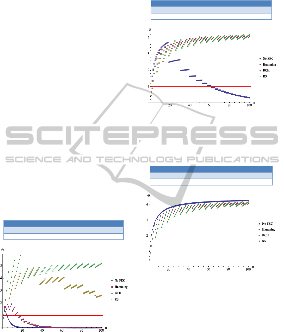
The next three figures (Figure 6-Figure 8)
compare the cases of different FEC codes grouped
by channel quality
(4∙10
,4∙10
4∙
10
in respect to n. For every diagram, a table is
included, which shows the optimal aggregation
number (the highest point of the graphs and the
corresponding number of required retransmissions.
Remark. The optimal aggregation number can be
much higher is case of BCH and RS codes, but the
authors considered n<100 aggregation numbers are
worth dealing with, because higher aggregation
numbers would cause much higher delays. For
example if the aggregation number n=100 and the
packets are generated on an hourly base, then the
aggregation delay can be as high as 100 hours. For
most real-world scenarios the delay should be within
a day.
Figure 6 compares FEC codes on the worst
quality channel. This scenario shows the energy cost
of different FEC codes the best. The graph
emphasizes, that not using any FEC is the worst, and
BCH and Reed-Solomon codes perform as the best.
It can be seen, that in case of lower aggregation
numbers
(10), Reed-Solomon is the best
solution, and from 2040 RS and BCH are at
the same level. When further increasing the
aggregation number RS code is the most efficient
again.
No FEC Hamming BCH RS
Opt. aggr. no.
2 9 37 18
No. of reps.
6 8 4 3
Figure 6: Comparison of FEC codes at BER=4E-3.
Figure 7 compares FEC codes on a channel with
4∙10
. It can be seen, that in case of
n>20 aggregation numbers, FEC codes provide
more energy efficient operation. The FEC codes
perform roughly the same.
No FEC Hamming BCH RS
Opt. aggr. no.
18 98 94 100
No. of reps.
2 2 2 2
Figure 7: Comparison of FEC codes at BER=4E-4.
According to Figure 8 in good quality channels
there is no benefit of using FEC codes, because for
every aggregation number the case without FEC
performs as the best. The FEC codes just converge
to the graph of no FEC case.
No FEC Hamming BCH RS
Opt. aggr. no.
100 98 94 100
No. of reps.
2 2 2 2
Figure 8: Comparison of FEC codes at BER=4E-5.
5 CONCLUSIONS
This article discussed the energy efficiency of
different Forward Error Correction algorithms and
presented a method to calculate the optimal amount
of aggregation of the data packets in terms of power
consumption, while taking into account the Bit Error
Rate characteristics of the wireless channel.
With the help of the methods shown in this paper,
developers and researchers can optimize the energy
consumption of their wireless sensor network
protocol.
ResearchonPayloadAggregationofPacketsinWSNs
193

ACKNOWLEDGEMENTS
This research has been supported by BME-Infokom
Innovator Nonprofit Ltd.,
http://www.bme-infokom.hu.
This research has been sponsored by The European
Union’s Hungary-Slovakia Cross-border Co-
operation Programme. Building Partnership.
www.husk-cbc.eu, www.hungary-slovakia-cbc.eu
The content of this paper does not necessarily
represent the official position of the European
Union.
REFERENCES
Atmel, 2013. 8/16-bit XMEGA A3 Microcontroller. pp.1–
134.
Balakrishnan, G. et al., 2007. Performance Analysis of
Error Control Codes for Wireless Sensor Networks,
IEEE.
Bose, R.C. and Ray-Chaudhuri, D.K., 1959. Further
results on error correcting binary group codes.
Information and Control, 3(3), pp.279–290.
Etzion, T. and Vardy, A., 1994. Perfect binary codes:
constructions, properties, and enumeration. IEEE
Transactions on Information Theory, 40(3), pp.754–
763.
Fossorier, M.P.C., Lin, S. and Snyders, J., 1998.
Reliability-based syndrome decoding of linear block
codes. IEEE Transactions on Information Theory,
44(1), pp.388–398.
Galluccio, L. and Palazzo, S., 2009. End-to-End Delay and
Network Lifetime Analysis in a Wireless Sensor
Network Performing Data Aggregation. GLOBECOM
2009 - 2009 IEEE Global Telecommunications
Conference, pp.1–6.
Geibig, J. and Bradler, D., 2010. Self-organized
aggregation in irregular wireless networks. Wireless
Days (WD), 2010 IFIP, pp.1–7.
Kumar, P. and Jayakumar, M., 2010. Comparison of Bit
Error Rate for Propagation Mechanisms of Millimeter
Waves in a Practical Communication Systems
Employing PSK and FSK. PIERS Proceedings,
pp.292–295.
Lendvai, K. et al., 2013. Optimized packet size for energy
efficient delay-tolerant sensor networks with FEC,
IEEE.
Lendvai, K. et al., 2012. Optimized packet size for energy
efficient delay-tolerant sensor networks. In Wireless
and Mobile Computing, Networking and
Communications WiMob, IEEE th International
Conference on. Barcelona: IEEE, pp. 19–25.
Lin, S. and Costello, D.J., 2004. Error Control Coding,
Prentice Hall.
Sankarasubramaniam, Y., Akyildiz, I.F. and McLaughlin,
S.W., 2003. Energy efficiency based packet size
optimization in wireless sensor networks. In Sensor
Network Protocols and Applications, 2003.
Proceedings of the First IEEE. 2003 IEEE
International Workshop on. IEEE, pp. 1–8.
Sarwate, D.V. and Shanbhag, N.R., 2001. High-speed
architectures for Reed-Solomon decoders. IEEE
Transactions on Very Large Scale Integration (VLSI)
Systems, 9(5), pp.641–655.
Texas Instruments, Incorporated, 2014. CC1101 Low-
Power Sub-1 GHz RF Transceiver (Rev. I), Available
at: http://www.ti.com/lit/ds/symlink/cc1101.pdf.
Tian, Z., Yuan, D. and Liang, Q., 2008. Energy Efficiency
Analysis of Error Control Schemes in Wireless Sensor
Networks, IEEE.
Vuran, M.C. and Akyildiz, I.F., 2006. Cross-Layer
Analysis of Error Control in Wireless Sensor
Networks, IEEE.
Vuran, M.C. and Akyildiz, I.F., 2008. Cross-Layer Packet
Size Optimization for Wireless Terrestrial,
Underwater, and Underground Sensor Networks. IEEE
INFOCOM 2008 - IEEE Conference on Computer
Communications, pp.1–9.
Wei, D. and Chan, H.A., 2006. Clustering Ad Hoc
Networks: Schemes and Classifications, IEEE.
Wicker, S.B. et al., 1994. Reed-Solomon codes and their
applications, Inst of Electrical and.
Yen, H.-H., 2008. Optimization-based channel constrained
data aggregation routing algorithms in multi-radio
wireless sensor networks. Sensors, 9(6), pp.4766–
4788.
SENSORNETS2015-4thInternationalConferenceonSensorNetworks
194
