
A Policy-based Communications Architecture for Vehicles
Vassilis Prevelakis and Mohammad Hamad
Institute of Computer and Network Engineering (IDA), Technische Universität Braunschweig, Germany
Keywords: Vehicular Control Systems, Security, Trust Management.
Abstract: Despite the fact that numerous studies have indicated that vehicular networks are vulnerable to external and
internal attacks, very little effort has been expended in safeguarding communications both between elements
within the vehicle and between the vehicle and the outside world. In this paper we present a mechanism that
allows communications policy (essentially who can talk with whom and the security parameters of the
channel) to be defined during the design of the software component and then adapted as the component
undergoes integration first within subsystems and so on all the way to the final integration in the operational
vehicle. We provide a mechanism that can maintain the integrity of the policy throughout the development
effort and, finally, enforce the policy during the operation of the component in the production vehicle.
1 INTRODUCTION
1
Within a complex environment, such as that of a
vehicle, there are multiple concurrent
communication streams that enable the various
subsystems to synchronize with each other,
exchange state, etc. Some of this communications is
via internal buses while others rely on wireless links
(both short range and wide area). An example of the
former are status messages from sensors mounted on
the car tires sent over wireless links to the
appropriate ECU; while an example of the later are
transmitted status messages and received commands
from the manufacturer or vehicle owner command
center (Sprenger H., 2010). In addition, passenger
furnished devices (laptops, cellphones, tablets, etc.)
may also need to communicate with on-board
systems for status updates, access to the
entertainment system etc. Moreover, when the
vehicle is sent to the service depot, all kinds of
diagnostic equipment will need to exchange
information with the on-board systems.
Currently most if not all of this communication is
exchanged either in cleartext or over links with weak
security, which means that a malicious third party
can listen-in or even inject false data and/or
commands into the communications channel
(Checkoway S. et al., 2011), while (Sharafkandi S.
et al., 2012) reports the need to ensure timely
1
This research has been sponsored by the Deutsche Forschungs-
Gemeinschaft, under project “Controlling Concurrent Change.”
delivery of specific messages. A very detailed threat
analysis against the wireless communications link
between the on-board system and the pressure
sensors on the tires published in (Rouf I. et al., 2010)
demonstrates the dangers inherent in cleartext
telemetry. In this case, the “adversary” managed to
inject false tire pressure readings into the telemetry
thus triggering a warning on the dashboard.
Ultimately, the fake data caused the ECU to crash
requiring replacement. A more determined adversary
could reverse engineer the ECU code to discover
vulnerabilities that could lead to a successful code
injection attack (Checkoway S. et al., 2011). This
would result in the commandeering of the ECU itself
with many adverse safety and security implications.
A similar situation exists in civil aviation where
the Aircraft Communications and Reporting System
(www.acarsd.org) messages are sent in the clear so
anybody can listen in and, given the necessary
equipment, inject forged data. The wireless nature of
these communications make attacks much easier, but
in many vehicles, the wired communications buses
may be also accessible to malicious parties. The
trend of extending the instrumentation buses to
every corner of the vehicle, makes it even more
likely that a bus will become accessible to a
determined attacker. In other words, wired or
wireless, communications are vulnerable to attack.
The interaction between systems may also create
vulnerabilities: In (Laarouchi Y. et al., 2009) the
authors note that it is extremely important to control
who may talk to whom, so that less critical tasks may
155
Prevelakis V. and Hamad M..
A Policy-based Communications Architecture for Vehicles.
DOI: 10.5220/0005325001550162
In Proceedings of the 1st International Conference on Information Systems Security and Privacy (ICISSP-2015), pages 155-162
ISBN: 978-989-758-081-9
Copyright
c
2015 SCITEPRESS (Science and Technology Publications, Lda.)

not interfere with more critical ones. Matters are
further complicated by the sharing of
communication buses by applications of mixed
criticality and or security, ranging from the mundane
(such as courtesy lights) to safety critical (such as
stability control and braking). These concerns extend
to civil aviation as well. For example the US Federal
Aviation Administration expressed concerns about
the fact that there exists connectivity between
“passenger domain computer systems [and] airplane
critical systems and data networks.” (Federal
Register, 2008)
While there are still few actual attacks, the ease
with which researchers have managed to exploit
vulnerabilities in vehicular platforms has made
evident the need for increased vigilance. Borrowing
from legacy networks researchers have suggested
the well tried methods of protection, such as
firewalling (Keromytis A. et al., 2007), Intrusion
Detection monitors (Muter M., 2009), and so on.
However, none of these techniques addresses the
root problem of these vulnerabilities, namely that the
basic design of the internal network allows anybody
to talk to anybody else. Even in cases where there
are multiple networks, bridged by specific ECUs,
actual attacks have demonstrated that such bridges
offer only nominal resistance to attackers (Eckert C
et al., 2013).
On the other hand, trying to impose a
comprehensive system to control communications
within the vehicular platform using traditional
techniques, such as packet filters on all ECUs is
guarantied to cause configuration problems both
during initial integration, but also during the
upgrades throughout the lifetime of the platform.
The reason is that static access control matrices are
not effective in a changing environment and must be
augmented either by update procedures (e.g. during
reconfiguration) or by a more flexible mechanism.
Moreover, as the number of ECUs increases, so does
the number of the filters that must be configured on
each ECU. Clearly this does not scale well, and is
likely to lead to configuration errors that may stop
the vehicle from functioning as intended, or, worse,
create vulnerabilities that a potential attacker can
exploit.
In addition to access control, we must also
consider what type of security protection we must
grant the various communications links (Laarouchi
Y. et al., 2008). The resource-constrained nature of
embedded environments, and the time-critical nature
of some of these communications implies that we
need to be more selective in the type of protection
we apply to these links (Mahmoud B. et al., 2010).
Moreover, traditional algorithms may be too
resource hungry and could be replaced by low
latency, low power ones such as elliptic curve
cryptography or compressed certificates (Olive M.,
2001).
A technique called the “distributed firewall”
(Ioannidis S. et al., 2000) whereby security policy is
defined centrally and distributed to all computing
platforms in the network offers great promise in
achieving the goal of total control over all
communication links. The key differentiation
between the distributed firewall and the installation
of packet filters on every ECU is that in the latter
case there is no easy way to specify the security
parameters of the communications links and that the
packet filters must be installed in each ECU
separately,. In the case of the distributed firewall, the
security policy is centrally managed and can
accommodate link security parameters.
Nevertheless, creating this security policy is a
very difficult task requiring detailed knowledge of
possible communication paths between all possible
components of the system, making system evolution
(whereby such interactions may change), labor
intensive and error prone.
Our approach is to integrate the evolution of the
security policy into the software development
workflow, allowing the policy to adapt to changing
circumstances during development, integration and
maintenance, so that on one hand the intentions of
the initial designer are preserved, while, on the other
hand, the policy is customized to the requirements of
the actual operational platform.
For example, the designer of a subsystem may
require a communications link to, say, a temperature
sensor, and include appropriate policy to this effect.
Latter, when this subsystem is integrated into a
vehicular platform, the basic policy may be
augmented by the system designer. For example,
depending on the way the particular subsystem is
integrated into the overall architecture, certain
aspects of the communication policy (such as link
integrity, privacy, priority) may need to be specified.
Later on during final integration the policy will be
further refined to include the actual parameters that
define the communications link (e.g. source and
destination addresses, integrity and/or encryption
algorithms, authentication methods and so on).
However, this is not sufficient as adaptations to
the policy may subvert it, or may misinterpret
assumptions made earlier on in the development
process. We, therefore, require that policy is
protected from design all the way to the actual
platform. In order to achieve this, we created a
ICISSP2015-1stInternationalConferenceonInformationSystemsSecurityandPrivacy
156

Figure 1: Domains, subsystems, and communication links.
framework that protects via a trust management
mechanism the initial policy and its refinements at
every stage in the development process. In this way,
at each level, policy may be adapted only in the
manner that the original designer envisioned thus
ensuring that the original design assumptions are
maintained. Moreover, mechanisms running on the
actual platform can verify that the supplied policy
conforms with the initial design policy and may use
it automatically to decide whether communication
requests should be allowed to go through, or be
denied as inconsistent with the security policy.
We achieve this by encoding the various policy
statements and their refinements into trust
management credentials that are signed by the
competent authority: at the design level, the original
policy credential is signed by the designer (or
actually by the key of the company that designs the
component), then the credentials that refine the
policy at the implementation level are signed by the
company (or team) that implements the component,
and so on all the way to the actual integration of the
component to the target platform, where the final
platform-specific policy statements are signed by the
team that performs the final integration. We thus
have a chain of credentials that transfer trust from
the original designer to the policy enforcement
engine on the platform which decides whether to
allow communication requests to go through.
In the following section we analyze how we
implemented this framework though the use of an
actual subsystem used in a test vehicle.
2 PRINCIPLES OF OPERATION
In this section we use a vehicle headlight control
scenario to describe the interaction of various
components and the formulation and refinement of
communications policy from initial design to final
integration.
2.1 Scenario
Our sample configuration uses a subsystem, found in
practically every road vehicle, that controls the
operations of the vehicle’s headlights. We have
chosen this example because it is based on a
function most readers will be familiar with and
which requires multiple communications paths to be
established, both within the subsystem and between
the subsystem and other subsystems of the vehicle. It
consists of (a) the headlights circuit breaker that
controls power to the headlight lamps, (b) an
ambient light sensor, used for the automatic
activation of the headlights and to detect lamp
failure, (c) the headlight mode switch usually placed
on the steering wheel that allows the driver to select
the mode of operation of the headlights (on, off,
auto), (d) the headlights indicator, which is a visual
indicator to the driver that the headlights are
powered on, and (e) the headlights failure indicator,
which is another visual indicator that tells the driver
that there is a problem with the headlights. Although
these functions can be aggregated in one or two
ECUs, we will assume a more distributed
ACTUATOR
Headlight Mode Switch
Headlight Control
Ambient light sensor
Headlight circuit breaker
ACTUATOR
CONTROLLER
DAQ
DAQ
Instrument Panel Control
Caution and Warning
CONTROLLER
CONTROLLER
Headlight Indicator
APolicy-basedCommunicationsArchitectureforVehicles
157

configuration to allow us to show the
communication paths.
The headlights subsystem includes the headlights
controller, the ambient light sensor and the headlight
circuit breaker, while there are two more
subsystems, the Instrument Panel subsystem which
includes the controller of the instrument panel and
associated indicators, switches etc., and the Caution
and Warning subsystem which displays various
messages regarding the status of various components
in the vehicle. While both of these two subsystems
typically contain numerous components, in order to
keep the example simple, we show only the elements
that are relevant to our scenario and assume that the
Caution and Warning subsystem has a built-in
display for its messages, so it does not need to
communicate with any other devices within its
domain.
vendor_id == “ACME_INSTRUMENTS”
src_device_name == “headlight_control”
dst_device_name == “ambient light sensor”
src_device_type == CONTROL_PLATFORM
dst_device_type == LIGHT_SENSOR
connection_type == HP2HP # host:port to
host:port
security_level >= SL_INTEGRITY # link must
offer at least integrity
Figure 1 shows the interactions between the
headlights subsystem and the other two subsystems
in our sample configuration. Let us assume that the
driver wants to turn on the headlights. She moves
the headlight mode switch to the “on” position. This
is detected by the Instrument Panel controller which
in turn signals the headlight controller to turn on the
headlights. The headlight controller commands the
headlight circuit breaker to provide power to the
headlights. It then signals the Instrument Panel
controller that its instruction has been executed,
which then instructs the headlight indicator to show
that the headlights have been enabled. While the
headlights are turned on, the headlight controller
periodically checks the ambient light detector to
confirm that the headlights actually provide light. If
the ambient lights sensor reports a low light
condition, then the headlight controller will assume
that the headlights are malfunctioning and signal the
Caution and Warning controller to report the failure.
2.2 Security Policy Design
In Figure 1 we see the three domains of authority in
our example (Headlight control, Instrument Panel
control, and Caution and Warning). Communication
links inside each domain of authority are under the
control of the designer of each subsystem and are
fairly easy to define. However, communication links
that span domains, are quite complex since they join
components or subsystems that are potentially
designed by different teams, or even provided by
different vendors.
Each subsystem has its own separate security
policy to handle internal communications and a
template policy for the external communications.
For example a typical policy for the communications
link between the headlight controller and the
ambient light sensor would be:
The purpose of this policy fragment is to allow a
device of type
CONTROL_PLATFORM to talk to
another device of type
LIGHT_SENSOR. The policy
as it stands would imply that both devices are
standalone (i.e. that each is a separate host in the
network). However, at design time we generally do
not know whether a particular sensor, or actuator
will be standalone, or whether it will be integrated
within a larger controller. This will be determined
later on during integration. So we need to be able to
allow our policy to work even when the sensor is
grouped with other sensors in a data acquisition
module, or in a more powerful ECU. We, therefore,
define a hierarchy of device classes and allow
subsequent policy statements to map specific device
types to more general types, as long as they belong
to the same path within the device class hierarchy.
In Figure 2 we see an example of such a class
hierarchy whereby the most general element is the
MASTER_ECU. From there we can see a path that
includes the local control platform (
SEC_ECU), the
Data Acquisition Platform (
DAQ), and finally the
LIGHT_SENSOR device. This classification enables
us to refine policy, so that a group of sensors in a
DAQ platform can use policies such as the one
above to communicate with their respective
controllers.
In the above policy we also see that we specify
some of the link parameters, which in this case is the
security level. We use the “>=” expression to
indicate that we require at least link integrity
protection, but we can accept higher security levels,
such as one that offers privacy as well as integrity.
Finally the
HP2HP designation for the connection
type specifies that we want the communication link
to be between the two services (the controller and
the sensor) and we will not accept to share a
communication link with other services (Figure 3,
top). In cases where the designer wants a lower level
ICISSP2015-1stInternationalConferenceonInformationSystemsSecurityandPrivacy
158
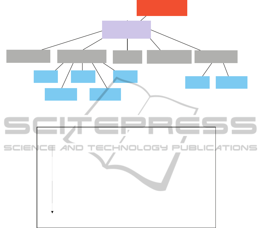
Figure 2: Class Hierarchy.
Table 1: Policy attributes change between different levels in the design.
Software Component Designer
Abstract
src_device_name == “Headlight Control”
dst_device_name == “Ambient Light Sensor”
src_device_type == COMP_PLATFORM
dst_device_type == LIGHT_SENSOR
Integrator
i_src_device_name == “ECU12”
i_dst_device_name == “Sensor 52”
i_src_device_type == uPD-2343
i_dst_device_type == LS-X5
Platform
p_src_addr == 192.168.177.15
p_src_port == ANY
Specific
p_dst_addr == 192.168.175.134
p_dst_port == sensor
of security, she can specify that the particular pair of
devices can utilize an existing communication link
between, say, a data acquisition platform that the
sensor has been integrated with a local control
platform that the headlight controller has been
integrated (Figure 3, bottom).
2.3 Policy Refinement
So far we have seen how policy can be defined at the
designer level. We will now examine how the policy
can be refined as we move to the integration and
finally to the platform. In Table 1 we see how the
terms of reference change between abstraction
levels. In the design level we are dealing with a light
sensor, while at the integration level we talk about a
particular part, and at the platform level, about
specific network addresses and ports. The objective
of the policy framework is to maintain the security
relationships even as the attributes themselves
change
It is clear that we need to have some translation
between the different levels, but we cannot simply
rewrite the original policy credential as this would
invalidate its digital signature. We therefore need
separate credentials that map values, such as
i_src_device_type to p_src_addr from one
level to the next. Being trust management
credentials each one of them transfers trust to the
“licensee” and is signed by the private key of the
“authorizer”.
Let us follow a connection request from the
headlight controller to the ambient light sensor. This
request contains all the names that appear in Table 1
and is signed with the private key of the initiator,
which is in our case th e headlight controller. The
DAQ
Data Acquisition Platform
Local Control Platform
SEC_ECU
Master Control Platform
MASTER_ECU
Com. Bridge
Circuit BreakerDimmer
Actuator Control
ACTUATOR
Control Platform
CONTROLLER
Caution & Warning
Voltage
sensor
Light
sensor
Pressure
sensor
Temperature
sensor
Acceleration
sensor
APolicy-basedCommunicationsArchitectureforVehicles
159
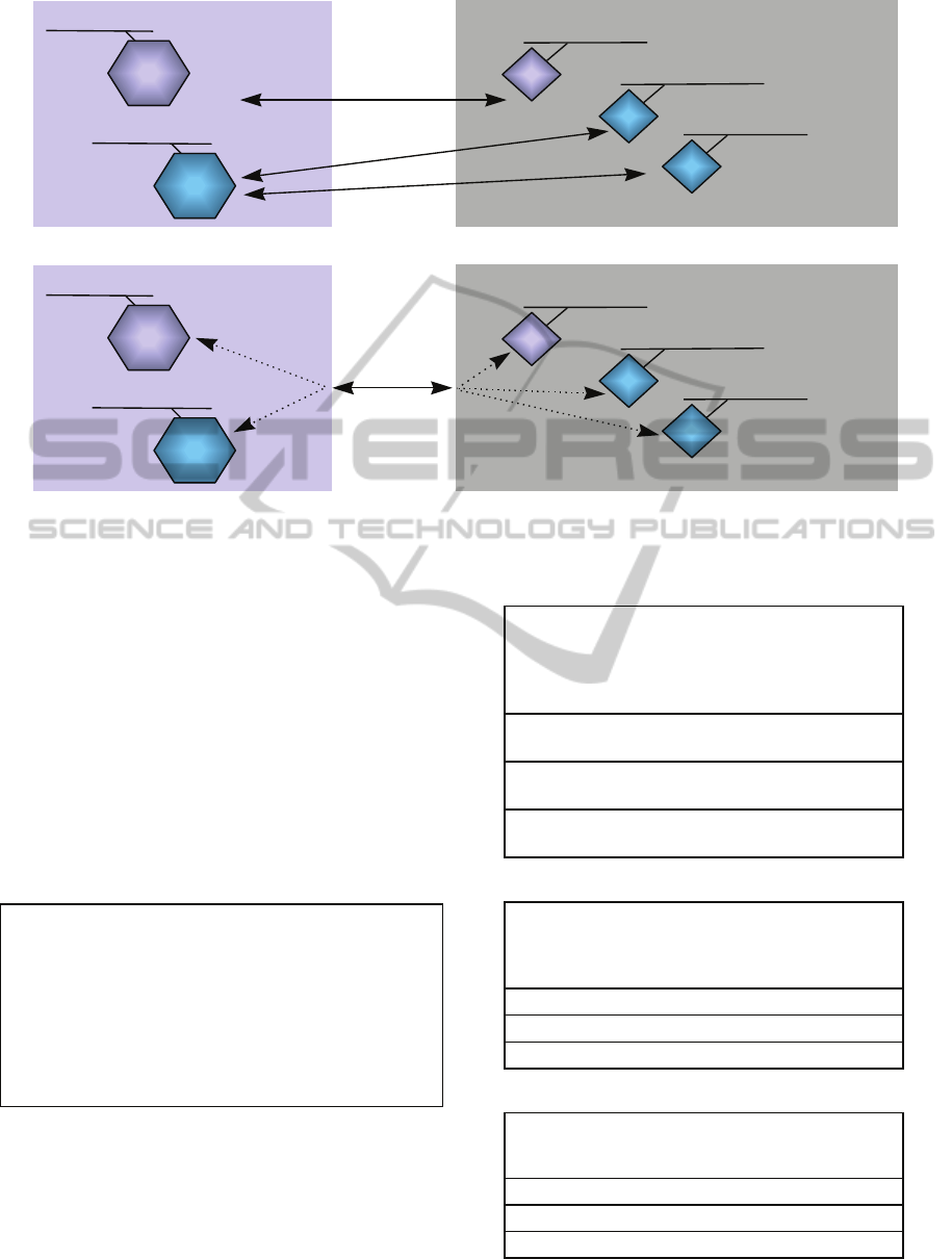
Figure 3: Communication links between components are implemented separately (top), and a single secure link combines
all communications between components (bottom).
ambient light sensor trusts the public key of the
designer, so for the request to be granted, a chain of
trust, must be established from the key of the
initiator to the key that the ambient light sensor
trusts. To save space, in the following example we
will only use one name from each level
(
src_device_type, i_src_device_name,
p_src_addr) although the actual credentials would
need to include the full list to avoid errors.
The process starts when the headlight controller
sends a request with the connection parameters for
the secure IP connection (we use IPsec in our
system):
src_device_name
= “Headlight Control”
i_src_device_name = “ECU12”
p_src_addr = 192.168.177.15
initiator_key
= headlight controller public key
nonce = transaction identifier
signed_by
=
headlight controller private key
Note that the transaction identifier is used to
prevent replay attacks and is generated by an initial
challenge - response exchange between the two
parties that wish to communicate. For this request to
go through, we need to send the appropriate
credentials.
a) the credential signed by platform designer:
if (src_device_name
== “Headlight Control”
&& i_src_device_name == “ECU12”
&& p_src_addr == 192.168.177.15
) -> MAXTRUST
LICENSEE
= headlight controller public key
AUTHORIZER
= platform designer public key
signed_by
= platform designer private key
b) the credential signed by the integrator:
if (src_device_name
== “Headlight Control”
&& i_src_device_name
== “ECU12”) -> MAXTRUST
LICENSEE = platform designer public key
AUTHORIZER = integrator public key
signed_by = integrator private key
c) the credential signed by the designer:
if (src_device_name
== “Headlight Control”
) -> MAXTRUST
LICENSEE = integrator public key
AUTHORIZER = designer public key
signed_by = designer private key
Local Control Platform
SEC_ECU
Headlight Control
CONTROLLER
Data Acquisition Platform
DAQ
Ambient light sensor
DAQ
Some temperature sensor
Some pressure sensor
Some Other Control
CONTROLLER
DAQ
DAQ
Local Control Platform
SEC_ECU
Headlight Control
CONTROLLER
Data Acquisition Platform
DAQ
Ambient light sensor
DAQ
Some temperature sensor
Some pressure sensor
Some Other Control
CONTROLLER
DAQ
DAQ
ICISSP2015-1stInternationalConferenceonInformationSystemsSecurityandPrivacy
160
By passing the request and the three credentials
into the trust management evaluation engine, we get
a
MAXTRUST answer which indicates that the request
should be approved. If however, any of the supplied
arguments is different from the ones specified in any
of the credentials, e.g. if the IP address is wrong, or
the device name is
ECU22 (rather than ECU12), then
the evaluation will fail and the request will be
denied. Adding additional names (e.g. link
parameters, source IP address, etc.) tightens the
conditions that will need to be satisfied (i.e. supplied
in the initial request) for the request to be granted.
Note that at the abstract level the credentials are
sparser, because the designer does not need to be
concerned with platform details such as IP addresses
and ports. These details are supplied later on, when,
during the platform customization process, are
assigned by the team responsible for configuring the
components to the target hardware.
In the above example we have seen the case
where the communication request is between
components of the same designer. In cases where the
communication needs to take place between
components of different manufacturers we must
establish a chain of trust between the key that the
target trusts (that of its designer) and the key of the
designer that created the component that initiates the
connection request. This is done by providing a
“bridging” credential such as:
if (vendor_id
== “ACME_INSTRUMENTS”
&& src_device_name
== “Headlight Control”
&& dst_device_name
== “Instrument Panel Control”
&& src_device_type
== CONTROL_PLATFORM
&& dst_device_type
== CONTROL_PLATFORM
&& connection_type
== HP2HP
&& security_level
>= SL_INTEGRITY) -> MAXTRUST
LICENSEE
= Headlight Control Designer public key
AUTHORIZER
= Instrument Panel Designer public key
signed_by
= Instrument Panel Designer private key
This essentially confirms that the designer of the
Instrument Panel Controller considers the Headlight
Controller compatible with their system.
3 ANALYSIS, FUTURE PLANS
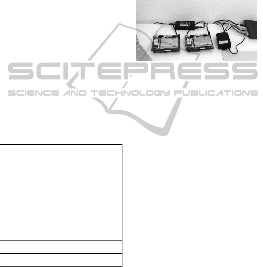
We implemented the above system on two single-
board computers running OpenBSD 4.8 , and a
raspberry pi computer running FreeBSD 10.0-
CURRENT (and later on the FIASCO microkernel)
linked to the same Ethernet switch (see Figure 4).
Figure 4: The Prototype system.
We used the Keynote trust management
framework (Blaze M. et al., 2001) for the policies.
For our prototype we used IPsec for the
implementation of the secure connections because it
is already integrated with the Keynote system under
OpenBSD. In environments where privacy is not
required, the policies could be combined directly
with the packet filtering and scheduling
mechanisms. We have extended both the Keynote
system to allow extensions to the credentials and the
IPsec implementation to implement certain aspects
of the API which allow a process to establish the
necessary security associations so that it can initiate
connection requests dynamically. A lot of this work
benefit from earlier work on distributed Trust
Management systems (Prevelakis V. et al., 2003)
and (Miltchev S. et al., 2008).
A key concern is the overhead of performing
multiple digital signature verifications, especially at
system startup. Although a modern processor can
cope with the load, we are looking into caching
verified policy credentials so that once a credential
has been verified, it is retained and can be loaded
directly without signature verification.
We also would like to experiment with
revocation of credentials. Typically, trust
management credentials include expiration dates in
the policy definition, so that they automatically
expire after some appropriate time interval (short for
high security, long for low security applications).
While this convention may be used for some
communications (e.g. links to or from hosts external
to the vehicle), it cannot be used for the internal
communications as it clearly inappropriate for use in
APolicy-basedCommunicationsArchitectureforVehicles
161

an embedded environment (you would not want your
car to stop working because some policy credential
expired). We are therefore investigating pre-loaded
policy that invalidates credentials (or keys that have
been used to sign credentials) and on-line key
refreshing.
Our long term goal is to leverage this technology
to enable dynamic change management in vehicular
platforms. We, therefore, plan to port all this
machinery to the CCC (Controlling Concurrent
Change) project platform (ccc-project.org) running
under the FIASCO.OC microkernel
(
http://os.inf.tu-dresden.de/fiasco) so
that it can be integrated into the CCC architecture.
4 CONCLUSIONS
The contribution of this paper is a framework that
allows communications policy to be specified early
in the design process of a software component and to
maintain the integrity of this policy throughout the
evolution of the component and its integration with
the platform. While such policy could be maintained
as project metadata and implemented as static files
(containing channel priorities, security parameters,
keys, etc.) this is both extremely tedious and error
prone. Static configurations also interfere with future
upgrades and configuration changes. By expressing
the requirements in a policy language and providing
the tools to adapt this policy during development
and integration we believe that the policy will
actually be installed in the target platform, thereby,
providing improved security for the entire system.
REFERENCES
Sprenger, H., 2010. “Maximising the efficiency of an
organisation’s fleets and assets,” Vodafone NZ, Jan.
2010. http://www.nsa.gov/research/_fi
les/publications/selinux_configuring _policy.pdf.
Checkoway S., et al 2011. “Comprehensive Experimental
Analyses of Automotive Attack Surfaces,” USENIX
Security, August 10–12.
Sharafkandi S., et al 2012. “Using EDCA to improve
Vehicle Safety Messaging,” IEEE Vehicular
Networking Conference (VNC), pp. 70-77.
Rouf I., et al 2010. “Security and Privacy Vulnerabilities
of In-Car Wireless Networks: A Tire Pressure
Monitoring System Case Study,” USENIX Security
Conf. Washington DC, August 2010.
Laarouchi Y., et al, 2009. “Ensuring Safety and Security
for Avionics,” Proc. ‘DASIA 2009 Conference, Data
Systems in Aerospace’, Istanbul, Turkey, 26–29 May
2009.
Federal Register, 2008. “Docket No. NM364 Special
Conditions No. 25-356-SC,” Federal Register: January
2, 2008 (Volume 73, Number 1), pages 27-29.
Keromytis, A. et al, 2007. “Designing Firewalls: A
Survey,” In Network Security: Current Status and
Future Directions, Christos Douligeris and Dimitrios
N. Serpanos (editors), pp. 33 - 49. Wiley - IEEE Press,
April 2007.
Muter M., 2009. “Risks of the Networked Car - Intrusion
Detection for Improved Automotive Security,” The
Fully Networked Car Workshop, PALEXPO, Geneva,
4-5 March 2009.
Eckert C., et al, 2013. “Security Issues of Multi Core
Architectures, The Automotive Case,” Information
Technology, Jan. 2013, pp 5-9.
Laarouchi Y., et al 2008. “Safety and Security
Architectures for Avionics,” Doctoral Consortium
(DCSOFT 2008) of the 3rd International Conference
on Software and Data Technologies (ICSOFT 2008),
5-8 July 2008, Portugal.
Mahmoud B., et al, 2010. “An adaptive security
architecture for future aircraft communications,” 29th
Digital Avionics Systems Conference (DASC), 2010
IEEE/AIAA, 3-7 Oct. 2010
Olive, M., 2001. “Efficient datalink security in a
bandwidth-limited mobile environment - an overview
of the Aeronautical Telecommunications Network
(ATN) security concept,” Proc. 20
th
Digital Avionics
Systems Conference, Vol. 2, October 2001, pp. 9E2/1-
10.
Ioannidis, S. et al, 2000. “Implementing a Distributed
Firewall,” Proceedings of Computer and
Communications Security (CCS), pp. 190-199,
November 2000, Athens, Greece.
Blaze M. et al, 2001. “Trust Management for IPsec.” In
Proceedings of the Internet Society Symposium on
Network and Distributed Systems Security (SNDSS)
2001, pp. 139 - 151. February 2001, San Diego, CA.
Prevelakis V., et al, 2003. “Drop-in Security for
Distributed and Portable Computing Elements,”
Journal of Internet Research, Volume 13 Issue 2,
MCB Press, 2003.
Miltchev S. et al, 2008. “Decentralized Access Control in
Networked File Systems,” ACM Computing Surveys,
40(3), pp. 10:1 - 10:30, August 2008.
ICISSP2015-1stInternationalConferenceonInformationSystemsSecurityandPrivacy
162
