
The “Everywhere Switch” using a Projector and Camera
Akira Nozaki and Katsuto Nakajima
Department of Information Systems and Multimedia Design, Tokyo Denki University, Tokyo, Japan
Keywords: Projector-camera Systems, Projector-based Display, Touch Detection, Virtual Touch Screen.
Abstract: We propose a virtual remote control interface called the “Everywhere Switch” as an alternative to multiple
remote controllers for many computerized home appliances. The interface consists of a group of virtual
touch buttons projected near the user from a projector affixed to a pan-tilt mount just below the living-room
ceiling. Methods to implement our system, including methods to search for a place to project the virtual
touch buttons, to extract finger and shadow regions on the virtual button area and determine their ratio, and
to detect touch operations, are described. We evaluated the precisions of the foreground extraction (finger or
its shadow) and the segmentation of the finger and its shadow under three different brightness conditions
(dim, semi-bright, and bright). The foreground extraction showed an F value of more than 0.97, and the
finger/shadow segmentation showed an F value of about 0.8 in all tested brightness conditions.
1 INTRODUCTION
Modern living spaces contain many devices that can
be operated by remote control, such as televisions,
air conditioners, and audio equipment. However,
there are hardware issues inherent to remote
controllers, such as limited battery life, deterioration
of operation feel as a result of abrasion, and usage
issues, such as losing the controller and having to
keep it near at hand. To resolve these issues,
operation of home electronics by other means has
been proposed, such as by hand gesture (Shimada et
al., 2013), smartphone (LG Electronics, 2013), and
wearable terminal (Logbar, 2014). However, it is
difficult to recognize complex operations from hand
gestures, and security issues make it undesirable to
allow unrestricted operation by a third party's
smartphone or wearable terminal.
As an alternative to such systems, we propose a
system that uses a projector to display a virtual
interface and a camera to recognize gestures by the
user, mainly fingertip movements near or on the
interface.
With respect to this virtual interface, several
input methods, including pointing (Borkowski et al.,
2004; Borkowski et al., 2006; Goto et al., 2010; Kim
et al., 2010) and touch (Homma et al., 2014; Dung
et al., 2013) have been proposed. Here, pointing is a
situation of a finger (or something like a stick) to
dwell at some virtual interface widget, and the
system will recognize it as the user’s intention of
selection of the widget if the situation continues for
a fixed period of time. Touch is an action for a
finger or something to contact with a virtual
interface widget such as a button. The system should
recognize the user’s intention of its selection.
Since touch feels more akin to using a real button
and has higher usability than pointing, we employ
touch input in the proposed system.
Methods that rely on a depth camera have been
proposed for recognizing touch operation by the user
(Jiang et al., 2012). However, since sufficient
accuracy cannot be expected from a depth camera in
our assumed environmental conditions, we employ a
normal optical camera for touch detection.
In this paper, the "Everywhere Switch," which
projects a virtual remote control touch button and
recognizes touch operation of the button by a single
camera installed beside the projector, is proposed. In
addition, various necessary functions are proposed
and evaluated.
2 PROPOSED SYSTEM
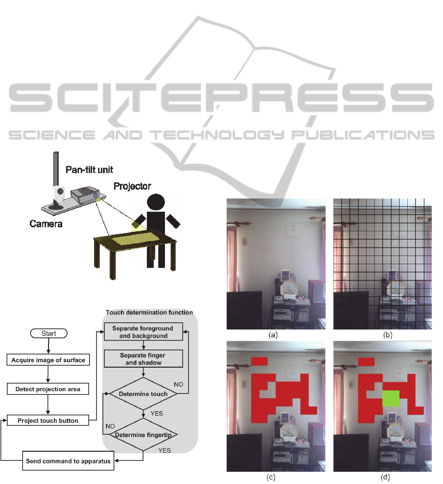
Figure 1 shows the configuration of the Everywhere
Switch system. The projector and the camera are
affixed to a pan-tilt mount to allow projection onto
an arbitrary location like the Steerable Camera-
Projector in (Borkowski et al., 2004). In our system,
115
Nozaki A. and Nakajima K..
The “Everywhere Switch” using a Projector and Camera.
DOI: 10.5220/0005307601150122
In Proceedings of the 10th International Conference on Computer Vision Theory and Applications (VISAPP-2015), pages 115-122
ISBN: 978-989-758-091-8
Copyright
c
2015 SCITEPRESS (Science and Technology Publications, Lda.)
the distance from the projector to the projection
plane is assumed to be about 400 cm.
Figure 2 shows the processing sequence of the
system with this configuration. Within this sequence,
there are two important functions. The first is the
search for a suitable area in the room near the user
on which to project the virtual button. For this, an
area detected as having a light color and a flat
surface is selected as the projection area. The second
is the determination of whether the virtual button,
which is displayed by the projector, has been
touched. This function can be further divided into
the following three subfunctions: a) separating the
foreground (e.g., a hand and its shadow) above the
virtual button from the background (i.e., the
projection plane on which the button light is
projected); b) further separating the foreground into
a finger region and a shadow region, and
determining the moment of touch operation from the
ratio of the region areas; and c) confirming whether
the touching part is a fingertip.
The implementation method for each function is
described below.
Figure 1: Configuration of the Everywhere Switch.
Figure 2: Processing sequence for the system.
2.1 Projection Area Selection
It is preferable that the projection plane be a flat
lightly colored surface so that the user can clearly
recognize the projected virtual touch button and that
the camera can observe the shadow cast by the
finger blocking the projector light in touch detection,
as described below. Furthermore, in the assumed
method of system use, it is necessary that the
projection point be within reach of the user's hand.
In the system proposed in (Borkowski et al.,
2004), several projection surfaces in the room are
pre-registered, and the user selects one of them for
the Steerable Camera-Projector to project. However,
the area or position of suitable surfaces for
projection may change if objects in the room are
moved. Therefore, our system finds a projection
surface on demand.
For our system to detect a projection area that
satisfies the above conditions, it first recognizes the
user’s invocation gesture and acquires an image of
the vicinity from the camera. The image input from
the camera is divided into predetermined small
rectangular blocks, and the variance of RGB values
in the blocks is calculated. Each block with variance
below a threshold and brightness above a threshold
is marked as a candidate for a flat area suitable for
Figure 3: Example of the projection area selection.
VISAPP2015-InternationalConferenceonComputerVisionTheoryandApplications
116
projection.
Next, candidate blocks of similar colors are
combined such that they are as close as possible to
the point where the gesture was detected in order to
secure an area with a size and shape corresponding
to the projected button. Figure 3 shows an example
of the processing sequence. In Figure 3, (a) shows
the image input from the camera, (b) shows the
image divided into blocks, (c) shows the candidate
blocks indicated in red, and (d) shows the region
selected as the projection area by combining
candidate blocks indicated in green. With respect to
(d), the point at which the gesture was recognized is
assumed to be the center of the image.
2.2 Touch Detection Function
In (Hartmann et. al, 2012), the tip of a hand or a
finger is detected by foreground shape analysis after
separating its shadow. Their system can estimate the
height of the fingertip from the interaction surface
by calculating 3D distance from the tip of the
shadow on the surface. However, in order to pursue
the precision of the distance estimation, the camera
should be placed far from the light source (i.e. the
projector), and its positional relation cannot be
adopted in our system.
For detecting a fingertip over or on a small
interaction surface, the virtual widget, Borkowski et
al. have proposed very simple and effective methods
(Borkowski et al., 2004; Borkowski et al., 2006).
Their metric for the touch detection is the ratio of
foreground occupation in the camera view. If the
ratio in the central region of the virtual widget is
very high and that in its surrounding region is
sufficiently low, the system recognizes a pointing.
However, as the distance of the foreground from the
widget is not estimated, false detection may occur
when a tip of some thin-rod like object or its shadow
happens to be observed over the central region of the
widget in the camera view. Therefore, in our touch
detection, we examine whether a user’s finger
(foreground) is close to the widget or not by the ratio
of the foreground to its shadow.
In order to make foreground shadows observable,
the camera is installed at a location slightly offset
from the optical axis of the projector (e.g., 50 cm to
the side in the setup described below) in the system.
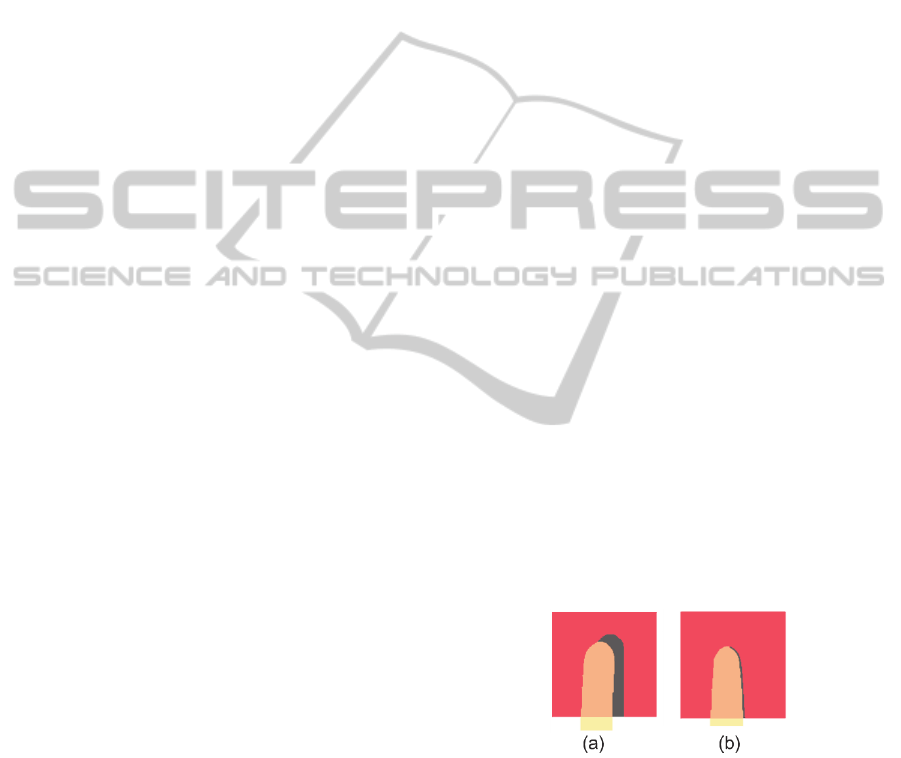
When a finger enters the region of the virtual
button projected by the projector, the finger and its
shadow appear in the camera image as shown in
Figure 4 (a). The shadow of this finger is large when
the finger is not touching the projection plane and
almost disappears when the finger touches the
projection plane, as shown in Figure 4 (b).
In this system, touch detection based on the
amount of this shadow is realized by the following
three functions. The first function separates the
background (button region) and the foreground
(shadow and finger region). The second function
further separates the foreground into a finger region
and shadow region, and the third function
determines whether a touch operation has been
performed from the area ratio of the finger and
shadow regions.
A certain degree of variation in environmental
brightness must be tolerated because the
hypothesized environment for the system is a living
space such as a typical living room. Other projector-
camera systems that use fluctuations in a shadow
region similar to the one in the present study include
a system that uses infrared LEDs to respond to
fluctuations in environmental brightness (Dung et al.,
2013) and a system that extracts the shadow region
by altering the color of the projected light (Homma,
2014). However, special equipment in addition to
the projector and camera is necessary for the
infrared LED system (Dung et al., 2013).
Furthermore, changing the button color temporarily
by altering the projected light in order to separate the
shadow region (Homma et al., 2014) can make the
user perceive it mistakenly as a system response to a
touch operation.
We propose a method for detecting touch
operations in environments where brightness
fluctuates that uses just an image input from a
monocular camera and without alteration of the
projected light. Our touch detection method consists
of the following process, described in Sections
2.2.1–2.2.4.
Figure 4: Example of the reduction in shadow consequent
on a touch operation.
2.2.1 Separation of Foreground and
Background
A background subtraction technique is used to
separate the foreground (the region containing the
hand, its shadow, etc.) from the background (the
projection plane onto which the button light is
projected). As detailed above, the method must be
The"EverywhereSwitch"usingaProjectorandCamera
117
able to adapt to a certain degree of fluctuation in
environmental brightness in a living space. However,
typical techniques that use fixed threshold values to
separate the background and foreground in the
background subtraction technique cannot handle
such fluctuation in brightness and cannot provide
high separation performance.
To handle brightness fluctuation, we set the
threshold used to separate the background and
foreground by a discriminant analysis method (Otsu,
1972). Specifically, the difference in pixel value at
each pixel location in the input image, which may be
the foreground or background, is expressed as the
distance from the prerecorded background pixel
value in the RGB space, and discriminant analysis is
applied to a histogram in which the horizontal axis
(bins) is the distance and the vertical axis
(frequency) is the number of pixels. The distance
may be Euclidean or Manhattan. In our current
implementation, we adopt Manhattan distance
because of its low computation cost. A pixel whose
distance is smaller (resp. larger) than the acquired
threshold is determined to be the background (resp.
foreground).
This discriminant analysis method assumes that
the histogram is diphasic or has a certain degree of
spread, and so it is not suitable if the foreground
within the button region is too small or too large.
Accordingly, in order to satisfy this condition,
threshold determination and foreground separation
by discriminant analysis are carried out in only when
the variance of the histogram exceeds a certain level.
2.2.2 Separation of the Finger and Its
Shadow
To obtain the area ratio of the finger region and the
shadow region, the finger and shadow regions are
separated. Accordingly, the threshold values for the
histogram of just the foreground image separated as
described in Section 2.2.1 may be found by further
application of discriminant analysis. Here, it is also
preferable that the histogram be bimodal or have a
certain degree of spread, as in Section 2.2.1. It is
therefore necessary to select feature values in order
to form a histogram that satisfies this condition
when a certain degree of area exists with finger and
shadow regions in the button region.
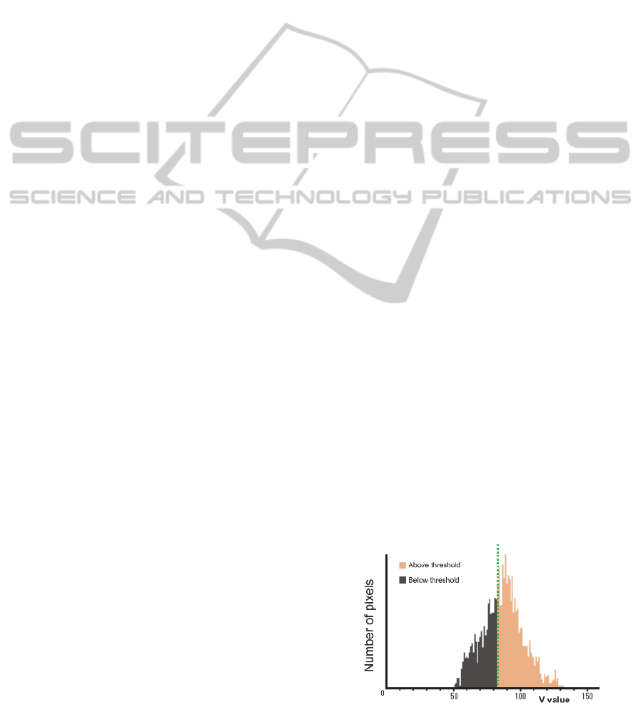
Saturation S (S in HSV space) is a possible
candidate for this feature value. Because saturation S
is easily affected by environmental contrast, the
feature values of V multiplied by S (expressed here
as "SS"), and also V were considered for a total of
three candidates. As a result of having considered
the merits and demerits of these values in a
preliminary experiment, we decided to switch
between using SS in the case of low environmental
brightness and V in the case of high environmental
brightness. Figures 5–8 show example foreground
histograms for each contrast environment with
respect to these two feature values.
As it is difficult to directly measure
environmental brightness from a camera input image
alone, we decided to use the separation metric,
employed in discriminant analysis, to perform
switching between the two feature values (SS or V).
The separation metric is a value that represents the
degree of separation among groupings and is defined
by equation (1).
n
1
·n
2
·(μ
1
- μ
2
)
2
/(n
1
+ n
2
)
2
(1)
Here, n
1
and n
2
are the number of pixels in each
group, and μ
1
and μ
2
are the average value of each
group. In other words, it represents how distinctly
the histogram has been separated into two. The
separation point that gives the maximum separation
metric for the histogram is chosen as the threshold to
divide the histogram into two groups.
If the maximum separation metric for SS
histogram is greater (resp. smaller) than that of V
histogram, the feature value SS (resp. V) is chosen
to separate the finger region from its shadow region.
In this way, the feature value can be selected that
gives a more bimodal histogram suitable for
separation.
Under conditions where a shadow region does
not exist from the start during a touch operation, and
under conditions where only shadow enters the
button region and the foreground is just shadow, it is
not suitable to attempt separation of finger and
shadow by discriminant analysis in the first place.
For this reason, the threshold is updated
(recalculated) by the above method only when the
variance of feature values SS and V for the
foreground are at or above a certain value and the
maximum value of the variance up to this point is in
the process of being updated.
Figure 5: V histogram for low brightness.
VISAPP2015-InternationalConferenceonComputerVisionTheoryandApplications
118
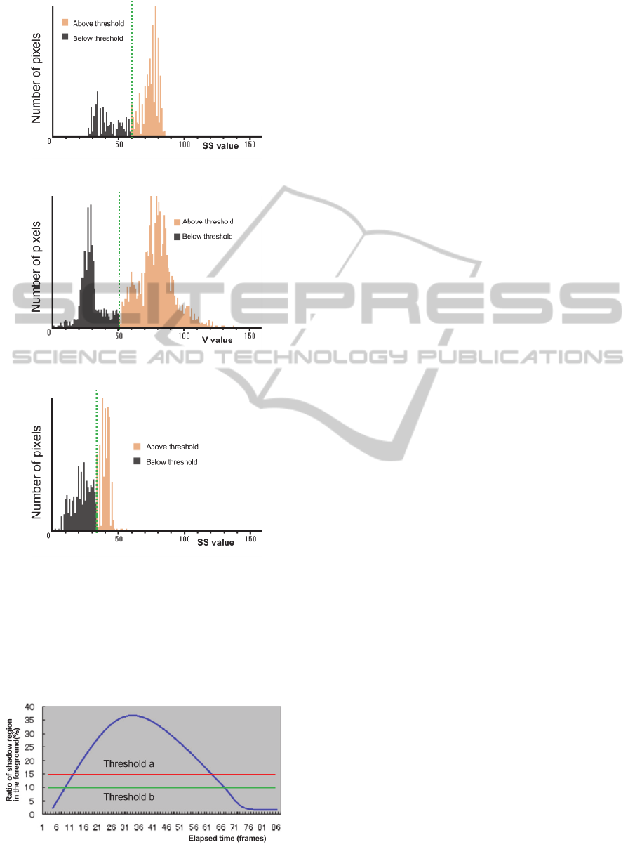
Figure 6: SS histogram for low brightness.
Figure 7: V histogram for high brightness.
Figure 8: SS histogram for high brightness.
2.2.3 Touch Operation Detection
A touch operation is detected by observing the area
ratio of the shadow region with respect to finger
region over time. Here, two thresholds, a and b, are
Figure 9: Relationship between shadow ratio over time
and thresholds a and b until touch operation.
used (a > b). A touch operation is detected only
when the ratio of shadow drops below threshold b
after temporarily exceeding threshold a. This makes
it possible to reduce false detection of touch
operations due to noise. Figure 9 shows the
relationship between thresholds a and b, and an
example of the changing ratio of the shadow region
from when the finger region enters the button region
until the touch operation.
2.2.4 Fingertip Detection
A lot of methods have been proposed to detect a
fingertip on some interface area by a camera.
However, having to wear a marker places a burden
on the user and is a problem with such a method.
Another method has been proposed that detects
fingertip position by matching the fingertip with a
circular template (Goto et al., 2010), but this has the
problem of high computational cost.
The present system determines whether the
finger that has entered the button region is a
fingertip intended to perform a selection without
using a marker or other attachable device.
Specifically, the system determines whether the
fingertip is above the button by analyzing the
condition of finger region entry into the four sides
enclosing the button with respect to the foreground
at the instant when a touch operation is detected.
As described in 2.2, the methods proposed in
(Borkowski et al., 2004) and (Borkowski et al.,
2006) are effective for determining whether a
fingertip is at the center of a widget by examining
the ratio of foreground occupation in the central and
the surrounding region. However, we make more
detailed examination for accurate detection.
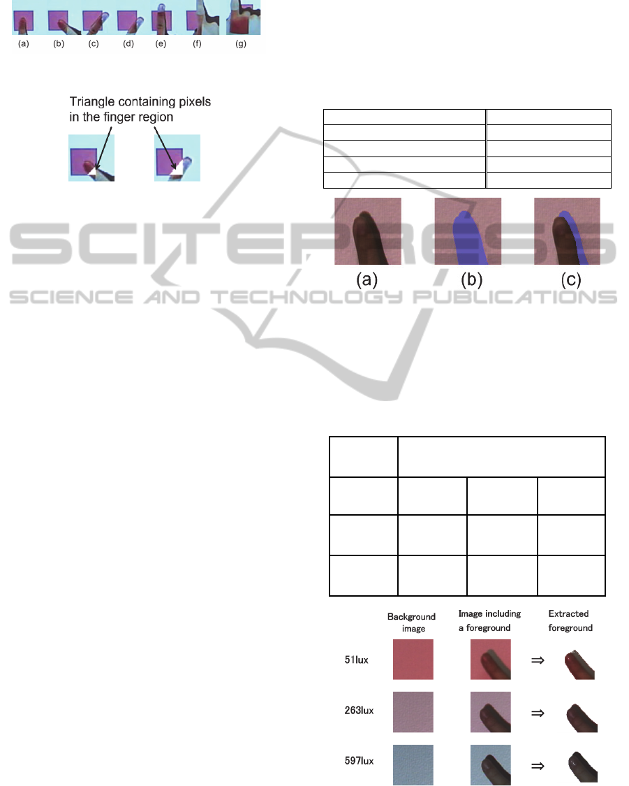
Figure 10 shows various patterns for the
condition of finger entry into the button region. It
can be seen that the fingertip is within the button
region in the case where the finger crosses just one
side of the button region (Figure 10a), and outside
the button region in the case it crosses two opposing
sides (Figure 10e), three sides (Figure 10f), or all
four sides (Figure 10g) of the region. In the case the
finger enters from two adjacent sides (Figure 10b, c,
and d) the decision is made by the following two
tests.
・If the vertex of the two sides entered is not in the
finger region (Figure 10c), the fingertip is outside
the button region.
・If the number of pixels within the triangle formed
by the intersection of the finger region on each
side and the vertex of the two sides (Figure 11) is
The"EverywhereSwitch"usingaProjectorandCamera
119
smaller than the number of pixels of the finger
region within the button region (Figure 10b), then
the fingertip is within the button region.
Figure 10: Patterns of hand entry into the button region.
Figure 11: Triangles made by the intersection of the finger
region with each side and the vertex of each side.
3 EVALUATION
As the precision of our touch detection depends on
the foreground separation accuracy and shadow
separation accuracy, we evaluated them under
various conditions described below.
Table 1 shows the test settings used in all
evaluations below. The camera was installed facing a
screen 50 cm almost exactly to the right of the
projector. The evaluation was performed under the
following three environmental light conditions
according to the brightness of the screen surface in
the absence of projected light: dim (51 lx), semi-
bright (263 lx), and bright (597 lx). The foreground
separation result when a finger was separated by 3
cm from the projection plane above a button region
projected in red and the shadow separation result
produced at that time were evaluated using
precision, recall, and F value. These values were
calculated using the manually separated results for
the foreground and background, or finger and
shadow, as the true values. Figure 12 shows
examples of manual foreground separation and
shadow separation.
The foreground separation results for the case
where the finger extended in a downward and down-
rightward direction are shown in Table 2. Figure 13
shows examples of foreground separation by our
method.
Similarly, the shadow separation results for the
case where the finger extended in a downward
direction are shown in Figure 14, and those for the
case where the finger extended in a down-rightward
direction are shown in Figure 15. The values on the
top of the bar graph are the F value, and those in the
bar graph are the precision (upper) and recall
(lower) values. Figures 14 and 15 show the results of
the foreground separation with a manually selected
feature (V or SS) and manually adjusted thresholds
for the separation.
In every case, the proposed method was found to
exhibit good, stable separation, close to the results
given by careful manual separation.
Table 1: Test setup.
Camera
Panasonic HDC-SD5
Projector
O
p
toma EP1691i
Camera-projector separation
50 c
m
Distance to the projection plane
400 c
m
Number of test subjects
7
(a) Original image
(b) Separation of foreground
(c) Separation of shadow
Figure 12: Original image and examples of manual
separation.
Table 2: Evaluation results for foreground separation
when a finger enters in the downward and down-rightward
direction.
F value [ precision, recall ] in three
environmental light conditions
Intrusion
direction
Dim
environment
(51 lx)
Semi-
b
right
environment
(263 lx)
Bright
environment
(597 lx)
downward
0.97
[0.99, 0.98]
0.99
[0.99, 0.99]
0.98
[1.00, 0.97]
down-
rightward
0.97
[0.99, 0.95]
0.98
[0.99, 0.97]
0.98
[0.99, 0.97]
Figure 13: Examples of the foreground separation by our
method.
VISAPP2015-InternationalConferenceonComputerVisionTheoryandApplications
120
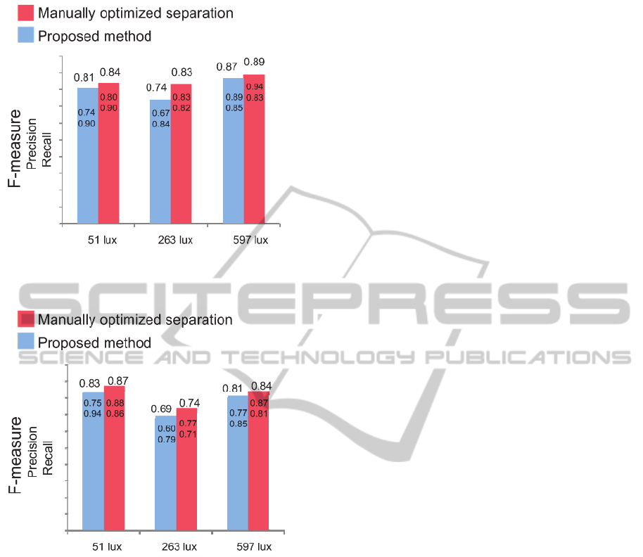
Figure 14: Evaluation results of shadow separation when a
finger extends in a downward direction.
Figure 15: Evaluation results of shadow separation in
cases where a finger extends in down and rightward.
4 SUMMARY AND FUTURE
WORK
We have developed the Everywhere Switch, which
uses a projector and camera to provide a remote
control interface for multiple devices in living
spaces. It consists of a group of virtual touch buttons
projected near the user. We also implemented a set
of methods to realize the Everywhere Switch. In
particular, precisely detecting the user's button touch
from the camera image is vital. We proposed a series
of methods to search for a place to project the virtual
touch buttons, to extract a finger and its shadow
regions on the virtual button area and calculate their
ratio, and a method of touch detection. Because
extracting the finger and its shadow region is key for
detecting a button touch, we evaluated the precision
of the extraction under three different brightness
conditions. The calculated accuracy shows that our
methods work precisely and are robust to variations
in environmental brightness.
In the future, we plan to install the proposed
system in an actual living space or other real-world
location, and will verify the effectiveness of the
proposed system, including control functions and the
effectiveness of the touch detection method
proposed in this paper. The button is currently red or
green, but tasks for future investigation include
examining other available button colors and the
effects of faint shadows produced by environmental
light other than the shadow produced by the
projector.
REFERENCES
Borkowski, S., Letessier, J., and Crowley, J.L. (2004).
Spatial Control of Interactive Surfaces in an
Augmented Environment. EHCI/DS-VIS Lecture
Notes in Computer Science, vol. 3425, pages 228-244.
Borkowski, S., Letessier, J., Bérard, F., and Crowley, J.L.
(2006). User-Centric Design of a Vision System for
Interactive Applications. IEEE Conf. on Computer
Vision Systems (ICVS ‘06), pages 9.
Dung, L., Lai, and G., Wu, Y. (2013). Shadow touching
for interactive projectors. IEEE International
Conference, pages 1798-1802.
Goto, H., Kawasaki, Y., and Nakamura, A. (2010).
Development of an Information Projection Interface
using a Projector-Camera System. 19th IEEE
International Symposium on Robot and Human
Interactive Communication, pages 50-55.
Hartmann G., and Wunsche, B.C. (2012). A Virtual
Touchscreen with Depth Recognition. Proceedings of
the Thirteenth Australasian User Interface
Conference (AUIC2012), pages 39-48.
Homma, H., and Nakajima, K. (2014). Virtual Touch
Screen “VIRTOS” – Implementing Virtual Touch
Buttons and Virtual Sliders using a Projector and
Camera. Proceedings of the 9th International
Conference on Computer Vision Theory and
Applications, pages 34-43.
Jiang, Y., Liu, and Y., Matsumaru, T. (2012). Applying
infrared radiation image sensor to step-on interface:
Touched point detection and tracking. IEEE SICE
International Symposium, pages 752-757.
Kim, S., Takahashi, S. and Tanaka, J. (2010). New
interface using palm and fingertip without marker for
ubiquitous environment. 9th IEEE/ACIS International
Conference on Computer and Information Science,
pages 819-824.
LG Electronics. (2013). HomeChat. www:http://
www.lgnewsroom.com/newsroom/contents/64064.
The"EverywhereSwitch"usingaProjectorandCamera
121

Logbar. (2014). Ring. www:http://logbar.jp/ring/.
Otsu, N. (1972). A Threshold Selection Method from
Gray-Level Histograms. IEEE Transactions on
Systems. Man. and Cybernetics. Vol. SMC-9. No. 1,
pages 62-66.
Shimada, A., Yamashita, T., and Taniguchi, R., (2013).
Hand gesture based TV control system — Towards
both user- & machine-friendly gesture applications.
IEEE Frontiers of Computer Vision, pages 121-126.
VISAPP2015-InternationalConferenceonComputerVisionTheoryandApplications
122
