
Omni-directional Reconstruction of Human Figures from Depth Data
using Mirrors
Tanwi Mallick, Rishabh Agrawal, Partha Pratim Das and Arun Kumar Majumdar
Department of Computer Science and Engineering, Indian Institute of Technology, Kharagpur 721302, India
Keywords:
Kinect, Depth Image, Mirror, Point-cloud, Camera-Mirror Geometry, Iterative Closest Point.
Abstract:
In this paper we present a method for omni-directional 3D reconstruction of a human figure using a single
Kinect while two mirrors provide the 360
o
view. We get three views from a single depth (and its corresponding
RGB) frame – one is the real view of the human and other two are the virtual views generated through the
mirrors. Using these three views our proposed system reconstruct 360
o
view of a human. The reconstruction
system is robust as it can reconstruct the 360
o
view of any object (though it is particularly designed for human
figures) from single depth and RGB images. These system overcomes the difficulties of synchronization and
removes the problem of interference noise of multi-Kinect system. The methodology can be used for a non-
Kinect RGB-D camera and can be improved in several ways in future.
1 INTRODUCTION
Omni-directional 3D reconstruction is the process of
capturing and recreating the shape and appearance of
any real object or scene from the captured images /
video using the techniques of computer vision and
graphics. 3D reconstruction has several applications
including modelling, rendering, virtual reality, robot
navigation, video games, and computational vision.
In this paper we reconstruct the omni-directional
3D models of human figures using single Kinect
1
depth frame. The corresponding RGB frame is used
to colourise the model. We use Kinect and attempt to
reconstruct the model from a single view using two
mirrors. There are three major challenges that a 3D
reconstruction system needs to address.
1. Estimation of the Depth
2. Capture of the 360
o
View
3. Reconstruction of the 360
o
view
Estimation of the Depth
Instead of using multiple optical cameras or costly
laser scanner and time-of-flight camera, we use easily
available and affordable RGB-D sensor Kinect, which
can capture depth and RGB data in real time in a syn-
chronous manner.
1
The method will actually work for any RGB-D camera.
Capture of the 360
o
View
Usually the 360
o
view is obtained from different
frames of the recorded data. In these techniques ei-
ther the camera or the object is rotated, or multiple
cameras are used to get multiple views in different
frames. But here we use two mirrors to get multiple
views (One real view and two virtual views) of the
object in a single frame using a single camera.
Reconstruction of the 360
o
View
Finally the reconstruction of the 360
o
view involves
the alignment of the multiple views based on the over-
lapping regions (surfaces) and stitching them all to-
gether into a single model. Virtual objects, gener-
ated through the mirrors, are nearly at twice the ac-
tual depth. Hence, a set of affine transformations is
performed to bring the virtual views in the coordinate
system of the real view. We do an initial registration
by estimating the Kinect-mirror geometry (Mallick
et al., 2013a). Subsequently Iterative Closest Point
(ICP) algorithm (Besl and McKay, 1992) is used for
fine alignment of the views by minimizing the error
between the overlapping surfaces.
The paper is organized as follows. Section 2 dis-
cusses the prior work in this area. We state the prob-
lem in Section 3. Section 4 discusses the solution ap-
proach. The solution has two parts. First part involves
estimation of Kinect-mirror geometry. It is discussed
559
Mallick T., Agrawal R., Das P. and Majumdar A..
Omni-directional Reconstruction of Human Figures from Depth Data using Mirrors.
DOI: 10.5220/0005306905590566
In Proceedings of the 10th International Conference on Computer Vision Theory and Applications (VISAPP-2015), pages 559-566
ISBN: 978-989-758-091-8
Copyright
c
2015 SCITEPRESS (Science and Technology Publications, Lda.)

in section 5. Second part deals with the reconstruction
of the 3D human model. It is discussed in Section 6.
Experiments and Results are explained in Section 7.
Finally, we conclude in Section 8.
2 RELATED WORK
3D reconstruction of symmetric objects and small
asymmetric objects using a single mirror has been
studied extensively. Most of these techniques work
for intensity images.
3D reconstruction using mirrors was pioneered by
Mitsumoto et al. (Mitsumoto et al., 1992) in 1992.
They presented a method for 3D reconstruction of
plane symmetric objects from a perspective 2D image
using a mirror. In 1998, Zhang and Tsui (Zhang and
Tsui, 1998) observed that an arbitrary object and its
image in a plane mirror constitute a bilaterally sym-
metric structure. Using this observation the authors
built a 3D reconstruction algorithm with good exper-
imental results. In 2005, Hu et al. (Hu et al., 2005)
proposed a technique to reconstruct asymmetric 3D
objects. However, it is limited to small table-top ob-
jects only. Both the direct and mirror images must be
clearly visible in the captured image. Also it is sensi-
tive to object segmentation in the image.
The availability of RGB-D cameras like Kinect,
has added an extra dimension to the reconstruction
techniques. The depth data is now directly avail-
able and the object segmentation process is easier and
more reliable. However, Kinect also has a limita-
tion for 3D reconstruction applications because when
more than one Kinects are used for reconstruction,
their IR’s interfere and degrade all the depth im-
ages (Mallick et al., 2013b). Particularly if the object
is extended (like a human figure), the interference is
perceptible and distributed.
Lanman et al. (Lanman et al., 2007) uses an RGB-
D imaging set-up and mirrors to reconstructs objects
in 3D. They use calibration, deal only with small ob-
jects, and employ multiple reflections. By the very
nature of the scenes handled, they exclude possibil-
ity of motion and extended objects like humans with
extended limbs. Moreover, the need of calibration re-
stricts the method to a laboratory set-up alone.
Recently, Akay and Akgul (Akay and Akgul,
2014) have proposed a method using Kinect along
with a mirror and an RGB camera to reconstruct small
objects in 3D. First stereo vision techniques are de-
ployed to obtain the virtual 3D objects (or virtual
cameras). Next the real and virtual views are seg-
mented and then a homographic relation between the
direct and mirror images are computed. The homo-
graphic relation is used to transform the virtual view
to the real view. The Kinect used here for obtaining
depth data is calibrated using the standard calibration
procedure.
There have been limited work in 3D human re-
construction from Kinect depth data using multiple
Kinects. In (Ahmed, 2012) Ahmed has reported a
system to acquire a 360
◦
view of human figures us-
ing 6 Kinects. A 3-Kinect set-up is also presented by
Tong et al. (Tong et al., 2012) for scanning full human
figures in 3D.
No work, however, has been done on 3D recon-
struction of Human figures by Kinect that uses mir-
rors. Hence the state-of-the-art motivates us to create
a set-up using two mirrors and a Kinect to reconstruct
360
o
view of a human. Two mirrors are placed at a
certain (about 120
o
) angle so that full human body is
visible from a single Kinect
2
.
3 PROBLEM STATEMENT
Given the Kinect depth image of a scene containing
two mirrors and a human, we intend to extract the hu-
man figure and build a 3D 360
o
point-cloud model
for it. The input image contains one direct and two
mirror-reflected images of the human figures (Fig-
ure 1). The output is the reconstructed 3D 360
o
point-
cloud of the human. We also colourise the model us-
ing the RGB image. For proper estimation and vali-
dation we make the following assumptions:
1. The human figure or any of its mirror reflections
does not occlude the other.
2. The human figure and its two reflections are all
within the depth range of Kinect.
3. The background is static.
4 SOLUTION APPROACH
To reconstruct the complete 3D model of a standing
human figure from a single depth frame with a 2-
mirror composition (as shown in Figures 1 and 2), we
need to solve the following:
1. Estimation of Kinect-Mirror Geometry: Given
any configuration of a Kinect and two mirrors
we first need to estimate the position (distance
and orientation) of each mirror with respect to the
imaging plane of Kinect. These would be used in
the reconstruction.
2
We do not use Kinect’s human segmentation algorithm;
hence any RGB-D camera can be used in place of Kinect.
VISAPP2015-InternationalConferenceonComputerVisionTheoryandApplications
560
2. Reconstruction the 3D Human Model: Given the
Kinect-mirror geometry (as estimated above), and
the depth and RGB images containing the direct
image of the human and his two mirror reflections,
we reconstruct the 3D point-cloud model of the
human figure. We colourise the model from the
RGB image.
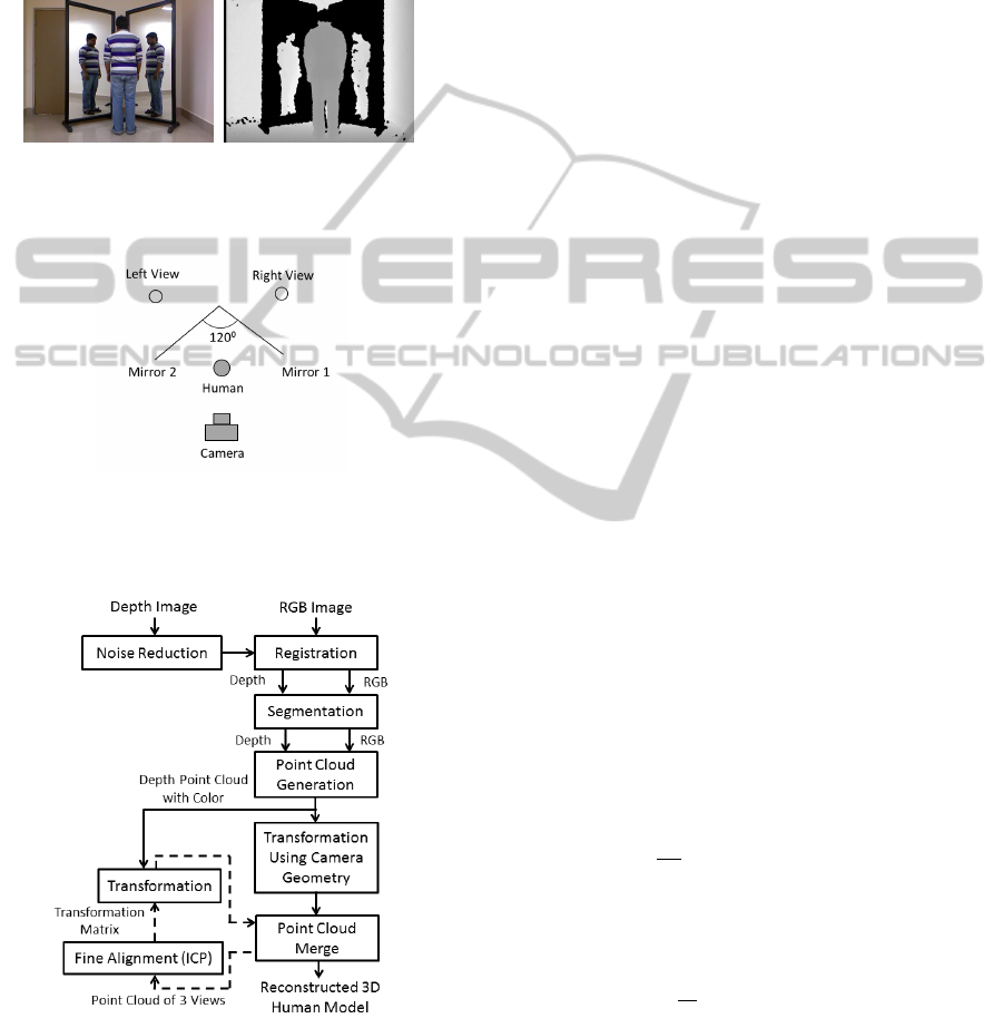
(a) (b)
Figure 1: Sample image of a human and his two mirror re-
flections. (a) RGB View (b) Depth View.
Figure 2: Schematic view of the 2-Mirrors-1-Kinect set-up
The architecture of the system is given in Figure 3.
Figure 3: The architecture of the 3D Human Reconstruction
System. The dotted arrows indicate an iterative flow.
5 ESTIMATION OF THE
KINECT-MIRROR GEOMETRY
In (Mallick et al., 2013a) Mallick et al. have pro-
posed a simple estimator using depth data to measure
the orientation and the distance of a mirror with re-
spect to the Kinect. While most approaches for the
estimation of mirror geometry work on pairs of cor-
responding points – one on the object and the other
on its reflection in the mirror; Mallick’s estimators
use the Kinect depth maps of a spherical ball (for its
symmetric shape) and its mirror reflection. The cen-
ter points of the ball and its mirror reflection in the
depth image are used for correspondence to solve the
Kinect-Mirror Geometry. We use this method to in-
dependently estimate the mirror geometry for each of
the two mirrors in Figure 2.
6 RECONSTRUCTION OF THE
3D HUMAN MODEL
After estimating the Kinect-mirror geometry, we use
the estimated parameters to reconstruct the 3D human
model using the set-up shown in Figure 2. From the
depth image of such a scene, we extract the human
figure and build a 3D 360
o
point-cloud model for it.
We also register the depth image with the RGB image
to colourise the 3D model. The steps for this task
are shown in the architecture diagram of the system
(Figure 3).
6.1 Noise Reduction
Depth images are first processed for noise reduction
using Bilateral filter (Tomasi and Manduchi, 1998).
It is a non-iterative edge preserving smoothing filter
given by the following expressions:
g(p) =
1
W
p
∑
qεΩ(p)
[S
p,q
∗ f (p)]
W
p
=
∑
qεΩ(p)
S
p,q
S
p,q
= N
σ
g
(||p − q||
2
) ∗ N
σ
d
(| f (p)− f (q)|)
N
σ
(t) = e
−
t
2
2σ
2
where f (.) is the raw (input) depth image, g(.) is
the processed (output) depth image, p is the pixel un-
der consideration, Ω(p) is the spatial support or win-
dow of interest around p, q is a pixel in Ω(p), W
p
is
the normalizing constant as defined above, ||.||
2
is the
Euclidean (L
2
) norm, and |.| is the absolute value.
Omni-directionalReconstructionofHumanFiguresfromDepthDatausingMirrors
561

Further, σ
g
is the geometric spread and is chosen
based on the desired amount of low-pass filtering. A
large σ
g
blurs more. Similarly, the depth spread σ
d
is set based on the sharpness in depth that we desire.
Naturally a large σ
d
flattens the depth details.
6.2 Registration of RGB and Depth
Images
Since Kinect uses separate sensors to capture RGB
and depth, these images are not aligned
3
and one im-
age needs to be rotated and translated by the cam-
era intrinsic parameters to register with the other.
This needs camera calibration (using some standard
scenes) to estimate the intrinsic parameters as ar-
ranged in the intrinsic matrix K,
K =
f
x
0 c
x
0 f
y
c
y
0 0 1
,
where f
x
and f
y
are the focal lengths along X
and Y axes respectively expressed in pixel units, and
(c
x
,c
y
) is a principal point that is usually at the image
center.
Incidentally, each Kinect is manufactured with ex-
actly the same specifications and has the same intrin-
sic matrix (Khoshelham and Elberink, 2012):
K =
586.34 0 320
0 586.34 240
0 0 1
(1)
We use this matrix to register the RGB image with
the depth image. This helps in the following:
1. Masks computed in RGB can be also used for
depth. This is useful for segmentation.
2. Colour association provides better visualization of
the reconstructed human figure.
6.3 Segmentation
Next we segment the patches of depth data of the one
direct and two reflected images of the human figure in
the scene. This is done by the following steps:
1. We capture the scene in RGB as well as depth with
and without the human figure. We register respec-
tive pairs of RGB and depth images. We then nor-
malize the RGB images between [0,1] inclusive.
2. We subtract the RGB image of the scene with-
out the human from the RGB image of the scene
3
The RGB pixel at (x, y) does not correspond to the
depth pixel at (x,y). Registration solves this problem.
with the human. We binarize this difference im-
age with a small threshold. Since the scene is
static, all the background (non-human) areas of
the binary image will be black (0) and the human
figures will be white (1). We treat this as a mask.
3. We compute the connected components in the bi-
narized difference image. The three largest com-
ponents correspond to the three views (other com-
ponents are removed). One of these components
(the direct one) would be larger than the other two.
So we can mark the human components as real
view segment (direct) and virtual view segments
(reflected). Naturally we can identify the left vir-
tual human figure from the right by checking the
extent of X-coordinates (the three views are non-
overlapping). The real human is in the middle.
4. We multiply the depth image (pixel-wise) with the
binary mask. This leaves us with a depth im-
age having the three segments corresponding to
the three views of the human figure and we know
which segment corresponds to which view.
We also tried depth-based method in our exper-
iments. But, as reported by (Mallick et al., 2014),
Kinect depth images suffer from lateral noise along
the boundary. Hence, segmenting the human figures
based from differences in depth images (with and
without human) is more prone to error than if the dif-
ference is done in RGB and the mask from it is used.
6.4 Point-cloud Generation
Kinect is a projective camera where all the rays em-
anate from the camera center and all the 3D points
lying on a ray are projected to the same image pixel.
The image point is the point where the ray meets the
focal plane of the camera. Thus both the world 3D
point and the image 2D point can be expressed in ho-
mogeneous coordinate notation.
A point A = [X Y Z]
T
in the world coordinate sys-
tem is represented in the projective space (in the ho-
mogeneous coordinate) as d ∗ [X Y Z 1]
T
, where d is
the scale factor. Let the image of point A in the image
plane be A = [X
m
Y
m
1]
T
. The 2D point is transformed
to 3D coordinate point as:
[X
mk
Y
mk
Z
mk
]
T
= K ∗ [X Y Z]
T
[X
m
Y
m
1]
T
= (1/Z
mk
) ∗ [X
mk
Y
mk
Z
mk
]
T
[X Y Z]
T
= (K)
−1
∗ [X
m
Y
m
1]
T
∗ Z
mk
where [X
mk
Y
mk
Z
mk
]
T
is the projected point in
the image coordinate system, Z
mk
is the depth at
(X
mk
,Y
mk
), and K is the Kinect camera matrix (Equa-
tion 1). Thus the 3D point-cloud is computed from
2D image of depth values.
VISAPP2015-InternationalConferenceonComputerVisionTheoryandApplications
562

Point-clouds are first generated for the real view
segment and each point is associated with its corre-
sponding color. For the points in the virtual view we
scale the image with the respective depth values while
generating the point-cloud
4
. With this correction the
virtual view segments get to the actual size of the hu-
man and get consistent with the real view segment.
6.5 Affine Transformations
The orientation and the distance of each mirror from
the Kinect imaging plane are estimated using the
method (Mallick et al., 2013a) as outlined in Sec-
tion 5. This method provides the rotational and trans-
lational parameters. Using these parameters, each vir-
tual view segment is independently transformed
5
(ro-
tated, reflected and translated).
The point-cloud generated from the virtual view
is rotated by the angle of the mirror with the Kinect’s
imaging plane. The axis of rotation is the normal di-
rection orthogonal to both the mirror plane and the
imaging plane. Using the Rodrigues’ Rotation For-
mula (Murray et al., 1994), the points are rotated as:
~
P
rotated
=
~
P∗cosθ+(~r×
~
P)∗sinθ+~r∗(~r·
~
P)∗(1−cosθ)
where
~
P
rotated
is the rotated point,
~
P is the point to be
rotated,~r is the unit direction vector of the axis of ro-
tation, and θ is the angle of rotation estimated from
the mirror geometry. After rotation the mirror plane
transforms to a plane parallel to the imaging plane. To
correct the reflected view through the mirror a reflec-
tion is required. The points are reflected as:
~
P
re f lected
=
~
P
rotated
− 2 ∗
~
P
rotated
∗~n
T
∗~n + 2 ∗~n ∗ dist
where
~
P
re f lected
is the reflected point,
~
P
rotated
is the
point to be reflected,~n is the unit normal to the reflec-
tion plane, and dist is the distance of reflection plane
from the origin. Next, translation brings the two vir-
tual view in same size as the actual:
~
P
translated
=
~
P
re f lected
+
~
P
real
−
~
P
virtual
where
~
P is the point to be translated,
~
P
real
is the 3D
correspondence point of the real view,
~
P
virtual
is the
rotated and reflected point of the virtual view corre-
sponding to
~
P
real
, and
~
P
translated
is the translated point.
These affine transformations (scaling was done
earlier) bring virtual view segments to their actual po-
sitions and in alignment with the real view segment.
4
Note that the virtual views are generated through the
mirror and hence they are nearly at twice the actual depth.
5
Derivations of transformations from (Rodrigues et al.,
2010) are used.
6.6 Merging of Point-clouds
The three point-clouds are now merged together to
form the 3D model. The merged cloud contains the
two transformed virtual view point-clouds and the un-
altered real view point cloud. The overlapping points
between the real and virtual point-clouds are not con-
sidered separately.
6.7 Fine Alignment using ICP
Algorithm
The estimated geometry parameters may be erroneous
leading to defects in the transformed views (and the
resulting merged point-cloud). Hence to improve the
results, regions of overlap are determined between the
point-cloud of the real view segment and the point-
clouds of the respective virtual view segments. Corre-
sponding pairs of points are then found in the regions
of overlap. The Iterative Closest Point (ICP) (Besl
and McKay, 1992) algorithm is applied to get a new
rotation and translation matrix. The point-clouds are
transformed with this new rotation and translation
matrix resulting in an improved merged point-cloud.
Computation of Overlapping Region
The overlapping region needs to be computed care-
fully as the result depends significantly on the choice
of overlap. For example, the overlapping regions be-
tween the real view (View 1) and the left view (when
the observer faces the Kinect) will occur on their left
boundaries and is computed as (Figure 4):
1. Compute the Centroid C for View 1.
2. Compute the leftmost point P on the boundary of
View 1. Trace a 1-pixel boundary from P in clock-
wise direction.
3. Mark the column at the mid-point between C and
P as the Threshold Line.
4. The threshold line intersects the boundary at mul-
tiple points. The topmost and bottommost points
are taken as the end points.
5. All pixels between the threshold line and the left
boundary form the possible region of overlap.
6. Repeat the above steps for View 2.
The overlapped regions as computed are usually
highly uneven. So a particular thickness of pixels
along the boundary is taken as the region of overlap
along the boundary. The length of the boundary seg-
ment for possible region of overlap is bounded by the
end points.
Omni-directionalReconstructionofHumanFiguresfromDepthDatausingMirrors
563
Figure 4: Computing region of overlap between Real View
and Left View.
7 EXPERIMENTS AND RESULTS
We have implemented the system in C++ using Win-
dows SDK 1.8 library
6
. We then carried out several
experiments to validate our system.
7.1 Experimental Set-up
The experimental set-up has been shown in Figures 1
and 2. Two mirrors are placed at nearly 120
o
angle to
each other. A Kinect is placed in front of the mirrors
along the middle. A human stands between the Kinect
and the mirrors. The set-up and image capture satisfy
the conditions stated in Section 3.
7.2 Results
We reconstruct the 3D point-cloud from the three hu-
man figures in the depth image and render the same
with the RGB image. In total 5 samples are tested.
We first capture the depth and RGB images with-
out and with the human figure. We subtract the for-
mer from the latter to get the patches of human figure.
We use bilateral filter on depth image to reduce noise.
This is shown in Figure 5.
Next we prepare the mask from RGB images and
extract the three segmented views in Figure 6. Using
these masks we create the point-clouds for each of the
views. Figure 7 shows the point-clouds. We rotate,
reflect, and translate each virtual view segment inde-
pendently using the parameters of the Kinect-mirror
geometry. The results are shown in Figure 8.
Outputs after the transformations are used for
merging the point-clouds. The alignment of the
merged point-cloud is improved through ICP algo-
rithm. Colour is associated with each point in the
6
http://www.microsoft.com/en-in/download/
details.aspx?id=40278
(a) (b)
(c)
Figure 5: Noise Reduction. (a) Background depth image (b)
Depth image with human (c) Difference depth image after
noise reduction.
(a) (b)
(c) (d)
Figure 6: Segmented Views. (a) Binary Components Mask
(b) Real View (c) Virtual Left View (d) Virtual Right View.
Figure 7: Initial Point Clouds.
point-cloud for better visualization. The final point-
cloud model is rendered in Meshlab
7
and rotated to
view and validate the 3D human figure from different
sides. For the 5 test subjects we find that the model
has been correctly constructed. A sample with three
rotated views for the running example is shown in
Figure 9.
While the Meshlab views provide a qualitative
7
MeshLab is an open source, portable, and extensible
system for the processing and editing of unstructured 3D
triangular meshes: http://meshlab.sourceforge.net/.
VISAPP2015-InternationalConferenceonComputerVisionTheoryandApplications
564
(a) (b)
Figure 8: Affine Transformations. (a) After Rotation (b)
After Reflection.
(a) (b) (c)
Figure 9: Views of the merged point-cloud. (a) View from
right (b) View from front (c) View from left.
validation for human reconstruction, we cannot get
quantitative estimate of accuracy from them. So to
quantitatively estimate the accuracy of our recon-
struction algorithm, we repeat the experiment for a
simple geometric box object shown in Figure 10.
We first take physical measurements of the length,
breadth, and height of the box and then estimate these
quantities from the 3D reconstructed model in Mesh-
lab. The results are given in the Table 1.
(a) (b)
(c) (d) (e)
Figure 10: Experiment with a box object. (a) RGB view (b)
Depth view (c) Reconstructed model viewed from right (d)
From front (e) From left.
Table 1: Validations of Reconstruction Accuracy.
Box Measurements Error
Dimensions Physical Estimated (%)
Length 48.5 48.80 0.62
Breath 28.5 27.49 3.54
Height 49.5 49.93 0.87
All dimensions are in cm.
The errors are quite low (less than 5%) and partic-
ularly accurate (less than 1%) for length and height.
The error is higher for breadth due to the specific
placement of the box in front of the mirrors. The box
has three pairs of faces – height × length, length ×
breadth, and breadth × height. It is placed on one
of its breadth × height faces which obviously is not
visible. Hence, fewer faces participate in the estima-
tions of breadth and height than length. Further, the
breadth directly faces the view and therefore it has
longer parallax error in its estimation. The estima-
tions can be improved if the box is imaged in more
than one position by changing the placement face and
the orientation angle.
7.3 Artefacts of the Reconstructed
Model
When we rotate the model in Meshlab (and zoom for
details) we find some artefacts. For example, when
we zoom in on the model in Figure 11 and view from
a certain viewpoint (Viewpoint 1 in Figure 11(a)), the
model looks continuous and perfect. However, after
we rotate and look from a different viewpoint (View-
point 2 in Figure 11(b)) it looks broken and striped.
(a) (b)
Figure 11: Artefacts in Reconstruction. (a) Continuous
View from Viewpoint 1 (b) Striped View from Viewpoint
2.
The stripes result from the different depth levels as
sensed by Kinect. Since the virtual views are obtained
at a certain angle (the angle of the mirror plane), each
stripe is a piece of depth values captured at an angle in
order to match the curvature of the point-cloud with
that of the human body. All the points at a particular
depth lie on a straight line in Viewpoint 2 giving rise
to the stripes-with-gaps. Similar artefacts can be seen
for the box in Figure 10(c).
8 CONCLUSION
In this paper, we reconstruct 3D point-cloud model of
a human figure using a Kinect and two mirrors. Single
depth and RGB frames are sufficient for the 360
o
re-
construction. The omni-directional visibility has been
achieved without moving the human or the Kinect and
Omni-directionalReconstructionofHumanFiguresfromDepthDatausingMirrors
565

without using multiple Kinects. Two mirrors have
been used to get three views in a single frame – one
is the real view of the human and other two are the
virtual views generated through the mirrors. We have
tested the system for five subjects and found good re-
construction in Meshlab. To quantify the accuracy of
the system, we have tested it with a box having known
dimensions. We are able to achieve accurate estima-
tions for the length, breath and height of the box after
reconstruction. However, the reconstructed model has
a few striped artefacts when viewed from oblique an-
gles. These are due to specific placement angles of
the mirror.
Our proposed system can be improved in several
ways and we are working on some of them:
1. Kinect-Mirror Geometry: The present system
uses two mirrors. Use of three or more mirrors
can be explored to improve the quality of recon-
struction, reduce artefacts (Section 7.3), and relax
imaging limitations.
2. Reduction of Artefacts: We intend to explore
methods to smooth the artefacts by suitable fil-
tering of the input depth image and output point-
cloud. Reconstruction from multiple frames can
reduce artefacts and make this method more ro-
bust. However, that would increase the computa-
tional load.
3. Set-up Constraint Relaxation: We intend to relax
some of the constrains of the imaging set-up (Sec-
tion 3) to allow for:
• Minimal partial occlusion between the human
figure and its mirror reflections.
• Slow motion of limbs for continuous recon-
struction over multiple frames.
4. Use of non-Kinect camera: The proposed method
does not use the human detection and segmenta-
tion capability of Kinect. Hence it can be ported
to work for other RGB-D cameras.
ACKNOWLEDGEMENT
The authors acknowledge the TCS Research Scholar
Program for financial support.
REFERENCES
Ahmed, N. (2012). A system for 360
◦
acquisition and
3D animation reconstruction using multiple RGB-
D cameras. URL: http://www.mpi-inf.mpg.de/˜-
nahmed/casa2012.pdf. Unpublished article.
Akay, A. and Akgul, Y. S. (2014). 3D reconstruction with
mirrors and RGB-D cameras. In Computer Vision
Theory and Applications (VISAPP), 9th International
Conference on.
Besl, P. J. and McKay, N. D. (1992). A method for registra-
tion of 3-D shapes. In Pattern Analysis and Machine
Intelligence, IEEE Transactions on, pages 239–256.
Hu, B., Brown, C., and Nelson, R. (2005). Multiple-view
3-D reconstruction using a mirror. Technical report,
University of Rochester.
Khoshelham, K. and Elberink, S. O. (2012). Accuracy and
resolution of Kinect depth data for indoor mapping ap-
plications. Sensors, 12:1437–1454.
Lanman, D., Crispell, D., and Taubin, G. (2007). Surround
structured lighting for full object scanning. In 3-D
Digital Imaging and Modeling, 2007. 3DIM ’07. Sixth
International Conference on, pages 107–116. IEEE.
Mallick, T., Das, P. P., and Majumdar, A. K. (2013a).
Estimation of the orientation and distance of a mir-
ror from Kinect depth data. In Computer Vision,
Pattern Recognition, Image Processing and Graphics
(NCVPRIPG 2013). Proc. 4th National Conference
on, pages 1–4. IEEE.
Mallick, T., Das, P. P., and Majumdar, A. K. (2013b). Study
of interference noise in multi-Kinect set-up. In Com-
puter Vision Theory and Applications (VISAPP 2013).
Proc. of the 9th International Conference on, pages
173–178. SciTePress.
Mallick, T., Das, P. P., and Majumdar, A. K. (2014). Charac-
terizations of noise in kinect depth images: A review.
IEEE SENSORS JOURNAL, 14:1731–1740.
Mitsumoto, H., Tamura, S., Okazaki, K., Kajimi, N., and
Fukui, Y. (1992). 3-D reconstruction using mir-
ror images based on a plane symmetry recovering
method. Pattern Analysis and Machine Intelligence,
IEEE Transactions on, 14(9):941–946.
Murray, R. M., Li, Z., and Sastry, S. S. (1994). A Mathe-
matical Introduction to Robotic Manipulation.
Rodrigues, R., Barreto, J. P., and Nunes, U. (2010). Camera
pose estimation using images of planar mirror reflec-
tions. In Computer Vision–ECCV 2010, pages 382–
395. Springer.
Tomasi, C. and Manduchi, R. (1998). Bilateral filtering for
gray and color images. In Computer Vision, 1998.
Sixth International Conference on, pages 839–846.
IEEE.
Tong, J., Zhou, J., Liu, L., Pan, Z., and Yan, H. (2012).
Scanning 3D full human bodies using Kinects. Visu-
alization and Computer Graphics, IEEE Transactions
on, 18:643–650.
Zhang, Z.-Y. and Tsui, H.-T. (1998). 3D reconstruction
from a single view of an object and its image in a plane
mirror. In Pattern Recognition, 1998. Proceedings.
Fourteenth International Conference on, volume 2,
pages 1174–1176. IEEE.
VISAPP2015-InternationalConferenceonComputerVisionTheoryandApplications
566
