
A Novel Stereo-radiation Detection Device Calibration Method using
Planar Homography
Pathum Rathnayaka, Seung-Hae Baek and Soon-Yong Park
School of Computer Science and Engineering, Kyungpook National University, South Korea
Keywords: Stereo-radiation Detection Device, Radiation Sources, Calibration, Homography.
Abstract: A radiation detection device, also known as a particle detector, is a device used to detect, track and identify
the presence of radiation sources within a given area or environment. In general, a stereo-radiation detection
device consists with two radiation detection devices and used to estimate 3D distances to radiation sources
accurately. In computer vision, device calibration is more important and to obtain accurate results using such
devices, they have to be calibrated first. Many stereo camera calibration methods have been introduced
throughout the last few decades but a proper stereo radiation device calibration method has not yet been
introduced. In this work, we propose a new stereo-radiation detector calibration method using planar
Homography. The calibrated devices are used to estimate 3D distances to radiation sources and we obtained
very accurate results with an error of less than 6%.
1 INTRODUCTION
In order to extract the metric information from 2D
images in 3D computer vision, one of the most
important steps we should consider is calibration. In
most of the computer vision experiments, we
encounter the necessity of calibrating devices,
cameras especially. These devices should be properly
calibrated first to acquire more optimized, higher
accurate results. Many work related to camera
calibration has been done throughout the last few
decades (Zhang 2000; Yu and Wang 2006; Kwon et
al. 2007; Wei and Ma 1993; Park and Park 2010),
initially in the photogrammetry community (Feng et
al. 2009).
In recent, radiation has become one of the vastly
discussed topics in around the world, and the
detection of radiation has also become equally
important. Many conventional portable cameras with
various kinds of detectors and collimators have been
used to acquire 2D radiation images (Lee and Wehe
2004). But yet; proper methods to calibrate radiation
detectors have not yet been introduced in computer
vision society.
When pan-tilt technique (Figure 1) is used along with
visualizing the radiation distribution (Yamashita et al.
2000), it is possible to obtain the radiation distribution
with a 2D image (Saganti et al. 2001). The radiation
level and bright light intensity values of the radiation
detector can be defined by the luminance value of the
image pixel in the measuring unit. Same as a
projector, obtaining images of a calibration pattern
from a radiation detector is not possible and most of
the previous calibration methods cannot be applied in
a stereo-radiation detection system.
A Proper projector-camera calibration method is
introduced in (Park and Park 2010) where the
projector is implicit as an inverse camera. Based on
that methodology, we propose a similar inverse
camera calibration technique to calibrate our
radiation detection devices. The system we have
implemented consists with two vision cameras and
two radiation detectors, and in our approach we first
generate a series of virtual calibration pattern images
(converted vision camera images which are assumed
to be acquired from the radiation sensors) using the
Homography translation relationship between vision
cameras and radiation detectors. Then we apply the
Zhang’s calibration method (Zhang 2000) on the
converted images to calibrate the radiation sensors.
The structure of the paper is as follows. Section 2
first describes the experiment setup used along with
the method used to visualize the radiation images
using a pan/tilt scanning process. Then we introduce
the method used to convert the vision images into
112
Rathnayaka P., Baek S. and Park S..
A Novel Stereo-radiation Detection Device Calibration Method using Planar Homography.
DOI: 10.5220/0005305401120116
In Proceedings of the 10th International Conference on Computer Vision Theory and Applications (VISAPP-2015), pages 112-116
ISBN: 978-989-758-089-5
Copyright
c
2015 SCITEPRESS (Science and Technology Publications, Lda.)
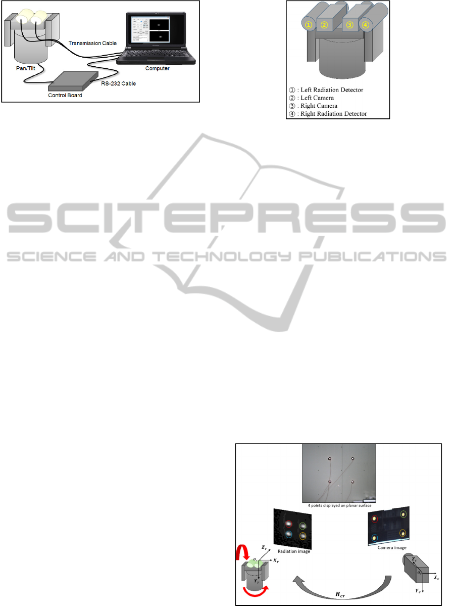
Figure 1: Experiment setup. Only two pinhole cameras are
mounted on the pan/tilt table.
radiation images using the Homography translation
relationship. Next the calibration method of stereo
radiation detection devices using these converted
images is also described. The accuracy of the
proposed calibration method is evaluated in section 3
whereas the conclusion and future works are
represented in Section 4.
2 PROPOSED METHOD
2.1 Experiment Set-up
The initial experimental setup used in our proposed
method to acquire images of radiation sources is
depicted in Figure 1. The radiation sensors we have
used in this setup are pinhole cameras and the reason
that we have used them is that they manage to produce
radiographs and photographs of objects that emit
radiation and visible lights. These cameras are
mounted on an automated pan/tilt table that is
controlled by a main control board and connected to
a general purposed computer via RS-232 cable. The
acquisition of radiation images using pinhole cameras
directly is possible, but the quality of the acquired
images is extensively low. Hence, we upgraded the
setup by implementing additional stereo vision
cameras in between pinhole cameras (Figure 2) to
obtain coincident 2D images. These coincident 2D
images are then converted to virtual radiation images
by applying Homography translation relationship
between vision and pinhole cameras.
2.2 Homography between Radiation
Sensor and Camera
The first step of the proposed method is calculating
the Homography translation relationship between left
and right pinhole-vision camera sets (H_crl,H_crr)
whereH_crl and H_crr represent the left and right
Figure 2: Stereo camera-radiation sensor setup.
Homography translation relationships respectively.
Light is a form of radiation that spreads similar to
gamma rays and in our method we have used bright
LED light sources displayed on a planar surface as
radioactive materials. At least four known image
points are required to calculate the Homography
translation relationship. We used the pan/tilt scanning
technique to acquire left and right image sets of LED
sources from both pinhole and vision cameras. The
center points of each LED image acquired are
calculated using the Gaussian fitting method (Hartley
and Zisserman 2003). Left and right Homography
translation relationships between left and right
pinhole-vision camera sets are then calculated using
these corresponding feature points. Figure 3 shows
how Homography translations are calculated.
2.3 Stereo-Radiation Detector
Calibration
The next step of the proposed method is converting a
few camera images into radiation images using
previously calculated homography translation
Figure 3: Experimental setup to calculate left and right
Homography matrices.
ANovelStereo-radiationDetectionDeviceCalibrationMethodusingPlanarHomography
113
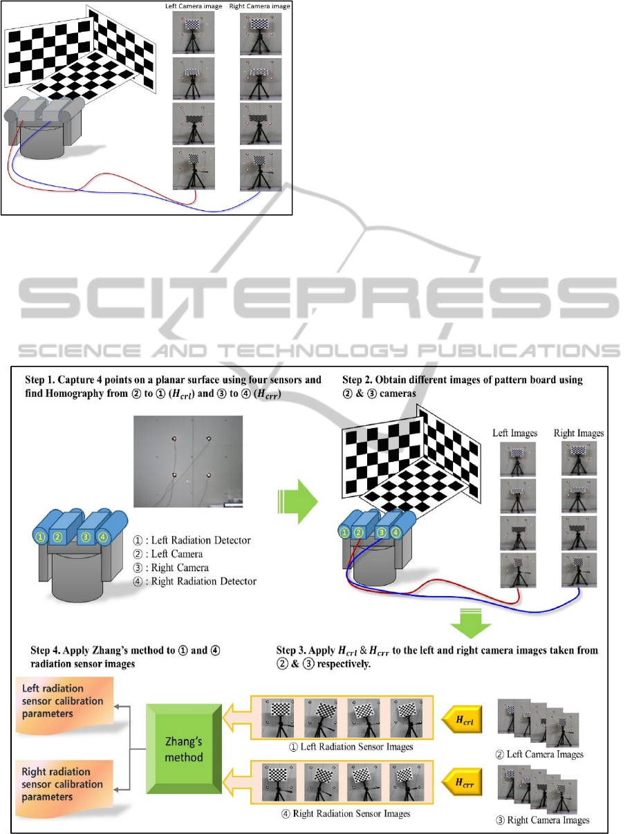
Figure 4: Capturing vision camera images of pattern board
for calibration.
relationships. This proceeding requires both left and
right cameras to observe a calibration pattern shown
at a few different orientations as shown in Figure 4.
If the orientation of stereo camera system is perpetual
and the same planar surface is used, the Homography
translation relationship between the acquired images
is said to be constant. This special feature is used to
generate the respective radiation images. For clear
representation, the camera-radiation detector system
is depicted in Figure 2.
After obtaining several images (at least 20 images) of
the calibration pattern in different postures from left
and right vision cameras, they are satisfied with the
left and right Homography translation matrices
(H_crl,H_crr) respectively. There the images
obtained from the left camera (number 2 in Figure 2)
are converted into the images that are estimated to
have been taken from the left pinhole camera (number
1 in Figure 2). Similarly, the images obtained from
the right camera (number 3 in Figure 2) are converted
into the images that are estimated to have been taken
from the right pinhole camera (number 4 in Figure 2).
Finally, the Zhang’s camera calibration method is
applied to calibrate the pinhole camera using these
converted images. The whole process is depicted in
Figure 5.
Figure 5: Overview of the whole calibration process.
VISAPP2015-InternationalConferenceonComputerVisionTheoryandApplications
114

Table 1: Intrinsic parameters of left and right radio sensors.
Camera
Focal length (
)
Focal length (
)
Principal point (
)
Principal point (
)
Left Camera
1048.01302 1044.52696 302.30848 297.63608
Right Camera
1048.92204 1044.95665 310.61240 302.64446
Table 2: Extrinsic parameters of the radio sensors.
0.00783 -0.04690 0.00209 -51.02962 -1.13604
Table 3: Results of experiment.
Dist (cm) P1 P2 P3 P4 Avg Std dev Error
300 303.037 293.658 290.358 300.039 296.773 5.019 3.227
330 330.363 346.611 339.973 329.079 336.506 7.194 6.506
370 378.757 375.874 373.683 359.664 378.494 4.513 8.494
400 416.115 417.167 400.495 409.566 410.836 6.642 10.838
3 EXPERIMENTS AND RESULTS
3.1 Intrinsic and Extrinsic Stereo
Camera Parameters
We can get the pinhole camera calibration parameters
after the converted virtual images are satisfied with
Zhang’s method. The intrinsic and extrinsic camera
parameters of both left and right pinhole cameras
aredepicted in Table 1 and Table 2. R_x,R_y and R_z
represent the rotation matrix whereast_x, t_y and t_z
represent the translation vector. Next, we performed
a 3D distance measurement experiment using these
calibrated cameras to evaluate the accuracy of our
proposed method.
3.2 3D Distance Estimation Test
We used a similar experiment setup what we have
used to calibrate our pinhole cameras. We have
displayed bright LEDs on a planar surface and
captured them from different distances using our
calibrated pinhole cameras. We arbitrarily varied the
position and distances of the device and recorded the
actual 3D distance values using a Bosch GLM 250 VF
Professional laser rangefinder. 3D distances are
calculated using triangulation and the results we
obtained had around 5~6% error, which assured the
accuracy of our calibration method. The results we
obtained are shown in Table 3.
4 CONCLUSIONS
In this paper, we proposed a new method to calibrate
a stereo-radiation detection system. In computer
vision, device calibration is done using images of a
particular calibration pattern. Since the quality of the
directly acquired images of the calibration pattern
using radiation detectors is considerably low, we used
translation relationships between radiation sources
and vision cameras to generate virtual radiation
sensor images. In our process, we used two pinhole
cameras as radiation detectors because they are
capable of photographing radiation such as X-rays
and gamma rays. Then we captured a series of left and
right vision images of the calibration pattern using
vision cameras, which are mounted in-between two
pinhole cameras. The Homography translation
relationships we found are applied to the vision
images to convert them into radiation images and the
pinhole cameras are calibrated using Zhang’s method.
ANovelStereo-radiationDetectionDeviceCalibrationMethodusingPlanarHomography
115

We performed a distance measurement experiment
using the calibrated pinhole cameras to check the
accuracy of our novel method. We used laser
rangefinders to measure the actual 3D distances and
compared them with estimated distance values
calculated using triangulation. We managed to obtain
higher accurate results with an error of about 5~6%.
As future work, we are planning to improve the
performance of the system by implementing
enhanced image processing techniques.
ACKNOWLEDGEMENTS
The project was performed with the assistance of the
civil-military technical cooperation promotion centre
of the defence research institute of South Korea and
the Korean atomic energy research institute, South
Korea.
REFERENCES
Feng, Y., Leng, J. and Zhang, Y., 2009. Calibration of
Forced Lane Changing Model Based on Close-Range
Photogrammetry. In 2009 International Workshop on
Intelligent Systems and Applications. IEEE, pp. 1–4.
Available at:
http://ieeexplore.ieee.org/lpdocs/epic03/wrapper.htm?
arnumber=5072773 [Accessed December 18, 2014].
Hartley, R. and Zisserman, A., 2003. Multiple View
Geometry in Computer Vision, Available at:
http://books.google.co.kr/books/about/Multiple_View
_Geometry_in_Computer_Visio.html?id=si3R3Pfa98
QCandpgis=1 [Accessed December 18, 2014].
Kwon, H., Park, J. and Kak, A.C., 2007. A New Approach
for Active Stereo Camera Calibration. In Proceedings
2007 IEEE International Conference on Robotics and
Automation. IEEE, pp. 3180–3185. Available at:
http://ieeexplore.ieee.org/lpdocs/epic03/wrapper.htm?
arnumber=4209581 [Accessed December 18, 2014].
Lee, W. and Wehe, D., 2004. 3D position of radiation
sources using an automated gamma camera and ML
algorithm with energy-dependent response functions.
In Nuclear Instruments and Methods in Physics
Research, Section A: Accelerators, Spectrometers,
Detectors and Associated Equipment. pp. 270–275.
Park, S.Y. and Park, G.G., 2010. Active calibration of
camera-projector systems based on planar homography.
In Proceedings - International Conference on Pattern
Recognition. pp. 320–323.
Saganti, P.B. et al., 2001. Visual assessment of the radiation
distribution in the ISS Lab module: visualization in the
human body. Physica medica : PM : an international
journal devoted to the applications of physics to
medicine and biology : official journal of the Italian
Association of Biomedical Physics (AIFB), 17 Suppl 1,
pp.106–112.
Wei, G.-Q. and Ma, S.D., 1993. A complete two-plane
camera calibration method and experimental
comparisons. 1993 (4th) International Conference on
Computer Vision.
Yamashita, M., Tonouchi, M. and Hangyo, M., 2000.
Visualization of supercurrent distribution by THz
radiation mapping. Physica B: Condensed Matter, 284-
288, pp.2067–2068. Available at:
http://www.sciencedirect.com/science/article/pii/S092
1452699028951 [Accessed December 18, 2014].
Yu, H. and Wang, Y., 2006. An improved self-calibration
method for active stereo camera. In Proceedings of the
World Congress on Intelligent Control and Automation
(WCICA). pp. 5186–5190.
Zhang, Z., 2000. A flexible new technique for camera
calibration. IEEE Transactions on Pattern Analysis and
Machine Intelligence, 22(11), pp.1330–1334.
VISAPP2015-InternationalConferenceonComputerVisionTheoryandApplications
116
