
Multi-Object Segmentation for Assisted Image reConstruction
Sonia Caggiano
1
, Maria De Marsico
2
, Riccardo Distasi
3
and Daniel Riccio
4
1
Master of Architecture and PhD, Digital Painting Restoration, Italy
2
Dipartimento di Informatica, Sapienza Universit
`
a di Roma, 00198 Roma, Italy
3
Dipartimento di Studi e Ricerche Aziendali (Mgmt IT), Universit
`
a di Salerno, 84084 Fisciano (SA), Italy
4
Dipartimento di Ingegneria Elettrica e Tecnologie dell’Informazione, Universit
`
a di Napoli “Federico II”,
80121 Campi Flegrei (NA), Italy
Keywords:
Image processing, Feature extraction, Feature-based indexing, Jigsaw puzzle, Cultural heritage.
Abstract:
MOSAIC is a tool for jigsaw puzzle solving. It is designed to assist cultural heritage operators in reconstructing
broken pictorial artifacts from their fragments. These undergo feature extraction and feature based indexing,
so that any fragment can be the key to queries about color distribution, shape and texture. Query results are
listed in order of similarity, which helps the user to locate fragments likely to be near the key fragment in
the original picture. A complete working protocol is provided to bring the user from the raw materials to a
working database. System performance has been assessed with both computer simulations and a real case
study involving the reconstruction of a XV century fresco.
1 INTRODUCTION
When a fresco or a piece of pottery shatters after some
traumatic event, reconstructing it from its fragments
is an as challenging as time-consuming and often te-
dious endeavour. Manual reconstruction requires ex-
treme amounts of time and resources, which are di-
rectly proportional to the number of fragments and
further grow as such fragments become smaller, till
to make the task downright impossible. What’s more,
in some cases the intrinsic fragility of the materials
imposes heavy constraints on the manipulation of the
pieces, which is necessary on the other hand to ver-
ify matches and correspondences. Fragility and un-
ease of handling are the most critical issues, and be-
come even more hindering when there is no reference
document representing the artwork, e.g., a fresco, as
a whole. The latter would not only support the re-
storer during the work but also reduce the number of
required matches, therefore decreasing the risk of fur-
ther degradation of the fragments.
In recent times, the use of advanced hardware as
well software resources has represented a dramatic
turning point. An interesting and recent example is
the reconstruction system implemented to work with
the artifacts found at the Roman archaeological site in
Tongeren, Belgium (Brown et al., 2010). An ad hoc
3D scanner has been set up for the acquisition of the
tridimensional shape of the fragments. The shapes are
submitted as input into an ad hoc software system that
matches the contours. However, the costs for such
sophisticated equipment (approximately 25,000 USD
for a scanner with suitable performance) are still quite
high when compared with the improvement in work-
flow: in this specific case, 17 true matches were con-
firmed out of the 6103 candidate matches proposed
by the system, compared with 3 matches previously
found manually.
As a further example, Brown et al. implemented
a semi-automatic system for fresco reconstruction
at the Akrotiri excavation site in Thera, Santorini,
Greece (Brown et al., 2008). The main purpose was
to produce a practical, user-friendly software system
that could provide the archaeologists with some au-
tonomy in cataloging and trying to reconstruct ancient
frescos. In this case, too, the system is partly based on
3D data, but there is heavier use of 2D image process-
ing techniques such as extraction of features based on
color, shape and texture.
From a theoretical point of view, the problem of
reconstructing pictures or generic documents from
fragments is connected to jigsaw puzzle solving. Puz-
zles are grouped into two types: (a) apictorial puz-
zles (where fragment shape is the only kind of infor-
mation available or significant) and (b) pictorial puz-
zles, where texture and color information is available
100
Caggiano S., De Marsico M., Distasi R. and Riccio D..
Multi-Object Segmentation for Assisted Image reConstruction.
DOI: 10.5220/0005274601000107
In Proceedings of the International Conference on Pattern Recognition Applications and Methods (ICPRAM-2015), pages 100-107
ISBN: 978-989-758-077-2
Copyright
c
2015 SCITEPRESS (Science and Technology Publications, Lda.)

and can be meaningfully used. For both types, it has
been shown that providing an exact algorithmic so-
lution is an NP-complete problem: computing time
grows unmanageably (non-polinomially) with prob-
lem size (Chung et al., 1998). As a consequence,
when the number of fragments is large, the time re-
quired for an algorithmic solution can be prohibitively
long. However, things are different when we settle
for a non-exact solution: there are heuristic and ap-
proximate techniques that provide acceptably accu-
rate solutions in reasonable times. The available liter-
ature offers several solutions for both types of jigsaw
puzzles—and several applications as well, mostly in
the fields of cultural heritage and ancient document
reconstruction.
Freeman and Gardner were among the first to face
the problem of apictorial jigsaw puzzles (Freeman
and Garder, 1964). Their approach was based on
five fundamental puzzle properties: orientation (not
known a priori), connectivity (presence or absence of
internal “holes”), perimeter shape (known/unknown a
priori), uniqueness (does the problem have one solu-
tion only?), radiality (type of juncture between frag-
ments). Fragment contours are represented as chain
codes whose length is used as a heuristic for reducing
the dimension of the search space. Papaodysseus et
al. tackle this problem in the specific context of wall
painting reconstruction (Papaodysseus et al., 2002).
Their paper is particularly interesting because it fo-
cuses on specific real-world issues that arise when
dealing with wall paintings: lack of information about
the original aspect of the painting, lack of uniqueness,
and especially the presence of very small fragments—
dealt with by the introduction of non-connectedness
(“holes”) to account for the loss of some of the pieces.
The technique for correspondence verification and
matching is based on local curve matching and is able
to cope with missing information.
It is possible to obtain more effective solutions by
exploiting all available information in a better way.
For this reason, most techniques that are actually used
in cultural heritage reassembly applications regard the
problem not as an apictorial, but as a pictorial puz-
zle. For instance, works such as (Chung et al., 1998)
and (Sagiroglu and Ercil, 2006) use color and tex-
ture information, respectively. However, their actual
testing has been limited to problems involving a rela-
tively small number of fragments. On the other hand,
Nielsen et al. devised a technique that uses no infor-
mation pertaining to single pieces, relying instead on
features of the whole represented pictorial scene. The
reported results for this technique show low error mar-
gins: the solution to a 320-fragment problem only had
23 pieces out of place—an error margin of 7.2%. This
example shows that not only shape, but all available
information can be quite useful to obtain the highest
possible accuracy: in this particular case, a good so-
lution was obtained by color and texture information
alone.
Summing up, the virtual reconstruction of picto-
rial fragments is an intrinsically hard problem, and ap-
proximate solutions are often all we can get. For this
reason, a number of sophisticated techniques drawn
from image processing are being included in more ad-
vanced systems. The most promising ones are based
on local texture analysis, chrominance analysis and
contour analysis on single fragments. Methods based
on the whole scene depicted are quite powerful, when
the original appearance is known or can be at least
partially inferred, and can provide further features to
consider. All these techniques can be used to produce
multimodal representations that allow users to refine
the solution progressively, adding detail and informa-
tion to the features of the solution search space.
The present paper proposes a system for the seg-
mentation and indexing of pictorial fragments: Multi-
Object Segmentation for Assisted Image reConstruc-
tion (MOSAIC). MOSAIC supports the rebuilding of
a fresco from fragments by a human operator. No in-
formation about the original appearance of the whole
artwork is assumed to be available. The system has
been tested on a real case study: the reconstruction of
a fresco from fragments found in the St. Trophimena
church in Salerno (Italy).
2 OPERATING CONTEXT
MOSAIC was expressly designed to support fresco
recomposition from fragments. Its architecture in-
cludes a protocol for image acquisition and process-
ing, so the single fragments can be cataloged and user
queries can be answered. A workspace is provided;
here, among the other actions, the user can virtually
rotate, translate and search for similar fragments. Fig-
ure 1 illustrates the system architecture schematically.
Figure 1: Architecture of the MOSAIC system.
Multi-ObjectSegmentationforAssistedImagereConstruction
101
During image acquisition, the real fragments are
laid in a white tray, whose bottom is covered by a
dark grey foam. The tray is placed inside a box for
object photographic acquisition, which is made by a
white curtain and two lateral spotlights. Beside the
tray there is a colorimeter, used to detect the possi-
ble need for automatic color corrections. A picture of
the tray is captured with a suitable device (in the spe-
cific case, an 8-Mpixel Canon camera), orthogonally
pointed from a height of 90 cm (35.4 in).
2.1 Segmentation
Segmentation is a delicate phase that has significant
influence over the rest of the procedure: several things
can go wrong. The purpose of this operation is to sep-
arate each fragment, so that individual features can be
extracted. In the first segmentation step, namely bina-
rization, the image is turned into B/W with no shades
of gray. Turning the original color photo into a binary
image might appear to be a trivial task, but it is not
so. If using naive thresholding on the raw images, we
have found that no single threshold value is effective
across all trays. Too low a value is ineffective at sepa-
rating one piece from another, while too high a value
yields pieces with “holes” inside them. In some cases,
a morphological fill operation is able to fill such holes,
but in other cases the piece comes out as two sepa-
rate fragments, and this cannot be repaired. An exam-
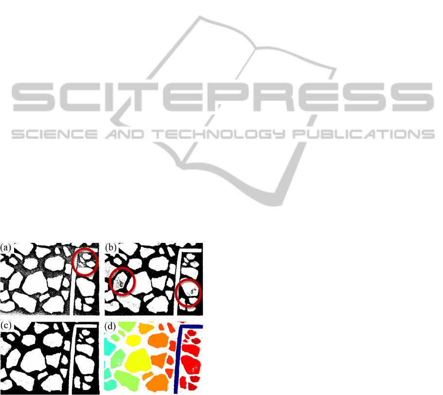
ple of problematic binarization is shown in Fig. 2 (a)
and (b).
Figure 2: Effect of threshold parameter t
B
on the segmenta-
tion of a tray image: (a) too low; (b) too high; (c) optimal
value t
B
= 0.1; (d) connected components detected after bi-
narization.
Since the naive approach on the raw images is in-
effective, the actual process of binarization needs to
amplify the difference between the fairer pixels (frag-
ments) and the darker ones (background foam—quite
dark but not exactly black).
The original image is represented in RGB space.
The single channels are stored in three separate ma-
trices r, g, and b. Two new matrices are then created:
M and m. The element M(i, j) of the new matrix M is
equal to the maximum over the three channels, i.e. the
maximum among r(i, j), g(i, j) and b(i, j)—therefore
each pixel in the new image represented by M con-
tains the largest (brightest) component of the origi-
nal image. The element m(i, j) of the new matrix m
is equal to the mean of r(i, j), g(i, j) and b(i, j)—
therefore the image represented by m is a greyscale
version of the original image. From M and m, the en-
hanced image I is built as follows. First,
I (i, j) ← M (i, j) ·
|
m(i, j) −δ
|
. (1)
The value δ in Eq. (1) is an experimentally determined
offset, which is a constant over all images. In our spe-
cific case, δ = 50. This is close to the mean lumi-
nance value of all pixels in the tray (both fragments
and background). The pixel values in I are then scaled
by dividing them by their mean value
¯
I:
I (i, j) ← I (i, j) /
¯
I . (2)
The new I is then turned into a 0–1 binary image by
thresholding according to the binarization threshold
value t
B
.
I (i, j) ←
(
0, if I (i, j) < t
B
1, if I (i, j) ≥ t
B
. (3)
We now explain the rationale for the operations just
described. The grayscale image m and the maximum
component image M are pointwise multiplied in or-
der to enhance the pixels where both m and M have
larger values. The resulting image is then divided by
its mean value to perform a sort of normalization of
the pixel values, so that the value of the threshold t
B
used for binarization does not depend on the partic-
ular image anymore. A value of t
B
= 0.1 has been
found to be effective for all tray images in our pool.
The final result of binarization can be seen in Fig. 2
(c).
The binary image just obtained becomes the input
to an algorithm for detecting connected components.
Ideally, each fragment should be one connected com-
ponent and vice versa, as in Fig. 2 (d). After a frag-
ment shape is extracted from the binary image, a mor-
phologic fill operator is applied in order to fill exist-
ing gaps or holes. Then specific information about
the newfound fragment is computed: area, perimeter,
orientation. The binary connected component will be
used as a mask to retrieve the fragment from the orig-
inal image by a pixel-wise logical AND operation.
ICPRAM2015-InternationalConferenceonPatternRecognitionApplicationsandMethods
102
2.2 Feature Extraction
The module following segmentation deals with fea-
ture extraction, so the fragments can be indexed and
conveniently retrieved. The features used for indexing
and retrieval are the shape(s) depicted on the fragment
and a spatiogram—which describes the spatial distri-
bution of color. Such extracted features allow a user
to search the fragment database in order to retrieve
fragments similar to a given “key” fragment on the
basis of similar color, similar shape, or similar spatial
color distribution.
2.2.1 Color
Information about color is represented by a spa-
tiogram of the fragment (Birchfield and Rangarajan,
2005). Briefly, a spatiogram is a histogram where
the count of occurrences of each color is augmented
with are the mean vector and covariance matrices,
respectively, of the coordinates of the pixels con-
taining that color. In a way similar to histograms,
spatiograms allow simple manipulations—especially
comparisons between image areas—without the need
to work out geometric mappings between the areas in-
volved. However, these augmented data structures do
further contain some spatial information about color
distribution. This spatial information provides in-
creased matching accuracy.
2.2.2 Shape
The information extracted regards the predominant
shapes of pictorial elements from a fragment, based
on the color of the shapes. The pixels first undergo a
clustering procedure based on color. Shape informa-
tion results from the analysis of the clusters in each
fragment. Color clustering is performed by a mean-
shift based method (Comaniciu and Meyer, 2002).
Such methods are non-parametric and fairly insensi-
tive to noise or similar low-level disturbances. More-
over, in mean-shift based clustering, the number of
clusters is not predetermined. As it turns out, in most
cases the result obtained is over-segmented for our
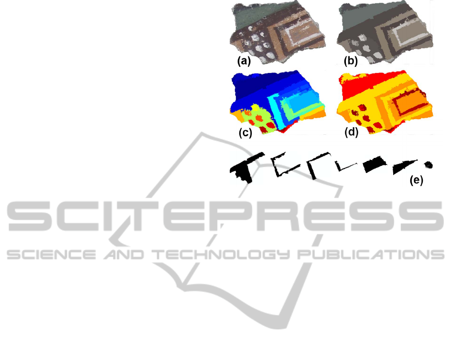
purposes. This is exemplified in Fig. 3.
In order to correct over-segmentation, a threshold-
ing “color radius” t
C
is determined, and the resulting
distinct RGB colors that lie at a distance less than t
C
are coalesced into a single color by re-labeling. In
our specific case, the effective value the threshold has
been determined experimentally at t
C
= 32. Cluster-
ing accuracy is significantly improved by this correc-
tion, as can bee seen comparing Fig. 3 (c) and (d).
Within a single fragment, each color cluster is
considered independently. The pixels belonging to
Figure 3: Shape extraction: (a) the original fragment; (b) af-
ter color clustering, original colors; (c) false colors show
oversegmentation; (d) thresholding and re-labeling; (e) ex-
tracted shapes.
one cluster (and then appearing to the system as
being of the same color) are fed to an algorithm
for connected component detection in order to de-
termine the shapes represented. This process is de-
picted in Fig. 3 (e). Each detected connected compo-
nent is in turn processed independently. The smaller
components—those whose area is less than 4% of the
total fragment area—are discarded as not significant
(small color holes, noise, as well as processing de-
fects in binarization, segmentation, color clustering,
or detection of connected components). Each frag-
ment F
h
is thus characterized by a variable number s
h
of shapes S
h
i
, i = 1 ...s
h
, whose surface area equals at
least 4% of the total fragment surface. These compo-
nents undergo contour detection so their shapes can
be geometrically described. Since this processing is
performed on a per-fragment basis, and since the fol-
lowing analysis is performed on single shapes in the
fragment, in order to simplify the notation we will
drop from now on the subscript identifying fragment
and shape. Shape S is analyzed through its contour
C. However, a further consideration is still needed
before proceeding. Not all components correspond
to relevant shapes, even if their area is over the 4%
threshold: some of them are just stains and contribute
nothing but noise to the system. Therefore, it is neces-
sary devise some relevance criteria to assign a higher
weight to relevant shapes than to stains. In order to as-
sess relevance in this context, contour smoothness is a
useful criterion. The underlying assumption, which is
supported by experts, is that the contour of a stain or
blemish is most often more jagged than the smoother
contour of a pictorial element. An example is pro-
Multi-ObjectSegmentationforAssistedImagereConstruction
103
vided in Fig. 4. On the other hand, they still contribute
to the spatiogram, therefore their possible color infor-
mation content is not lost in any case. According to
this, the shape processing continues as follows.
P
1
P
2
=0.682
P
1
P
2
=0.849
Figure 4: Smoothness ranks shape contours along the
jagged/smooth axis.
The contour C of a shape is represented as an or-
dered sequence of n
C
points:
C = {P
1
,P
2
,...,P
n
C
}, (4)
where the contour step count n
C
differs from shape
to shape. Given a point P
k
in C, let us consider an-
other contour point P
k+l
located l steps further along
the same path, so that the path from P
k
to P
k+l
has
step count l, which also corresponds to the lowest
distance between them. Let d(·,·) be the Euclidean
distance between any two points. The smoothness
for the subpath beginning at P
k
and spanning l points
C
k,l
= {P
k
,P
k+1
,...,P
k+l
} is computed as
ω(k, l) = d(P
k
,P
k+l
)/l . (5)
The actual value used for smoothness calculation de-
pends on n
C
and is l =
b
4log
2
n
C
c
. The smoothness
for the whole contour C is given by
ω(C) =
n
C
∑
k=1
ω(k, l). (6)
It assumes values in [0,1] and is used as a weight in
matching operations, as will be shown shortly.
Each shape is represented as a triple
S = hv,ω,ci. (7)
In this characterization, v = (v
1
,...,v
7
) is the vector
of the first 7 central moments of the shape. For a thor-
ough discussion of central moments and some of their
applications to pattern recognition, see (Hu, 1962;
Mercimek and Mumcu, 2005). The two remaining
elements in the triple, ω and c, are the shape smooth-
ness and mean color value, respectively. A fragment
F
h
containing s
h
shapes is therefore characterized by
s
h
such triples.
In order to compare two shapes S
1
= hv
1
,ω
1
,c
1
i
and S
2
= hv
2
,ω
2
,c
2
i, we compute their similarity as
the normalized dot product of their moment vectors
(i.e., the cosine of the angle between them), weighted
by the product of their smoothness values:
sim(S
1
,S
2
) = ω
1
ω
2
v
1
· v
2
T
|
v
1
||
v
2
|
. (8)
The similarity between two fragments F
1
and F
2
is
given by the maximum shape-to-shape similarity:
sim(F
1
,F
2
) = max
S ∈ F
1
T ∈ F
2
sim(S,T ) .
However, the most common type of query has a sin-
gle shape S as the key and goes through each frag-
ment indexed in the database looking for shapes with
high values of similarity to S. The similarity score as-
signed to a fragment is the maximum similarity score
achieved by a shape it contains. Smaller shapes are
discarded as not relevant. In a query based on shape,
the fragments are returned in decreasing order of sim-
ilarity to S.
3 THE SYSTEM INTERFACE
MOSAIC has a graphical user interface (GUI) that
allows the operator to create a work session where
the virtual fragments can be handled and reconstruc-
tion can be performed by retrieving relevant frag-
ments through queries based on shape, color or a com-
bination thereof. The interface is shown in Fig. 5.
A freshly created work session appears as a blank
workspace where fragments can be brought in. Here
is an outline of the main functionalities offered by the
interface.
Figure 5: MOSAIC: The graphical user interface and the
workspace.
ICPRAM2015-InternationalConferenceonPatternRecognitionApplicationsandMethods
104
• Workspace Management. Fragments can be
picked from the database, manually or via queries,
and brought into the workspace. Unneeded frag-
ments can be removed.
• Manipulation. The computer system operator
can translate or rotate fragments, similarly to an
archaeologist or other cultural heritage specialist
actually working with physical pieces.
• Search. It is possible to query the system by se-
lecting a fragment from the workspace. The query
can address a number of features, among which a
specific pictorial shape among those represented
in the fragment, the whole set of shapes repre-
sented, color distribution, texture (both shape and
color are relevant), and more.
4 EXPERIMENTAL RESULTS
Given the nature of the MOSAIC system, assessing
its performance quantitatively is significantly harder
than merely providing a qualitative judgment; there-
fore, a custom experiment has been designed. The
main objective was that of evaluating precision/recall
achieved by MOSAIC when attempting to retrieve the
fragments near a given one. This reflects the intended
use of the system by a human operator trying to recon-
struct shattered pictorial artworks. The chosen pic-
ture is a representation from the late XV century: the
Madonna della Misericordia or Madonna delle pietre,
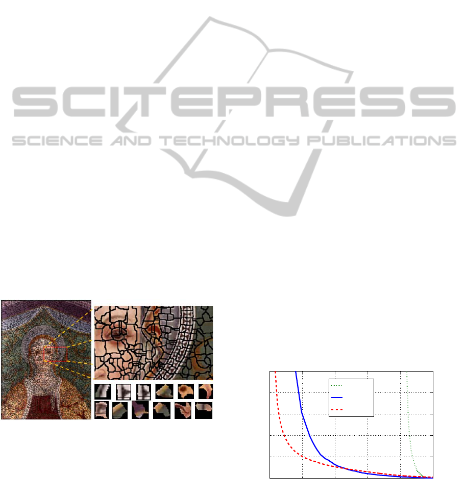
by an unknown author, shown in Fig. 6. The original
size is 140×90 cm. The acquisition was performed at
300 ppi, 24 bit RGB, yielding 1185 × 1566 pixels.
Figure 6: The image chosen for quantitative performance
assessment, with a detail of some of the fragments.
The picture was divided into irregularly shaped
small pieces, and the smallest ones were discarded
to simulate true fragmentation resulting from a trau-
matic event. The process produced about 2900 pieces
of sizes ranging from roughly 2 × 2 cm to 8 × 8 cm,
which were entered into MOSAIC and indexed.
It is reasonable to assume that adjacent pieces of-
ten tend to have similar textural features, so searching
for similar features should return fragments lying in
the same picture area as the key fragment used for
querying. Vice versa, in our context, given a key frag-
ment, the user wants to retrieve the fragments that lied
close to it in the original, pristine “canvas”, and it is
possible to assume that they present a similar texture.
Therefore, jigsaw puzzle solution can be simplified
by picking fragments from this smaller subset rather
than from the full set. In order to verify the effec-
tiveness of the indexing process, in this test setting
each fragment was characterized with the canvas co-
ordinates of its barycenter, computed assuming uni-
form mass distribution. Of course, this is not pos-
sible in real situations, since the problem to solve is
exactly related to the fact that we do not know the
original position of the fragments. During reconstruc-
tion, we might only recover the position of the already
identified ones, but only if we have an image of the
original artwork. However this was useful to analyze
some issues. Given a key fragment A used as a query,
let its barycenter be P
A
; a fragment B retrieved by
the system is deemed to be “close enough”—that is,
significant—if its barycenter P
B
falls within a circle
of radius t
M
centered in P
A
.
Since the geometry of the problem is based on
pixel units, the choice of a good value for the
threshold t
M
is strongly dependent on image scaling/
resolution. For this reason, the value of t
M
is ex-
pressed as the product of a proportionality factor δ in
the range [0,1] times a representative length quantify-
ing the image resolution, namely the diagonal length
L
d
, in our case 1964 pixels. Experiments have been
performed with δ = 0.02, δ = 0.05 and δ = 0.1, with
resulting values of t
M
= 39, t
M
= 98 and t
M
= 196 pix-
els respectively. Each fragment was used as the key
to a MOSAIC query. The average precision and recall
curves over all fragments are plotted in Fig. 7.
0 0.2 0.4 0.6 0.8 1
0
0.2
0.4
0.6
0.8
1
Recall
Precision
δ=0.02
δ=0.05
δ=0.1
Figure 7: Average precision/recall curves for MOSAIC with
δ = 0.02, δ = 0.05 and δ = 0.1.
Multi-ObjectSegmentationforAssistedImagereConstruction
105
The diagram shows that smaller values of δ gen-
erally yield better retrieval. The main reason is that,
for any given key fragment, the results of interest are
usually confined to a small space neighborhood of
the key rather than spread around widely. However,
there is an intrinsic problem issue that harms preci-
sion and recall. Looking at Fig. 6, it can be seen
that there are fairly extended regions with homoge-
nous features. For example, the whole halo area has
nearly homogeneous textural and chromatic features.
As a consequence, any two fragments belonging to
that area will be “close” in the feature space, while
actually lying at a potentially large distance in the re-
constructed picture.
4.1 A Real Life Case
The MOSAIC system has also been put to the test
in a real case study involving reconstruction from
6419 fresco fragments found during restoration work
at the St. Trophimena Church site in Salerno. Un-
fortunately, no information was available about the
original appearance of the frescoes: virtual recon-
struction was the only option to recover at least parts
of the original work without adding further damage
to the fragments. Examples of actual use are shown
in Fig. 8, depicting a reconstruction in progress, and
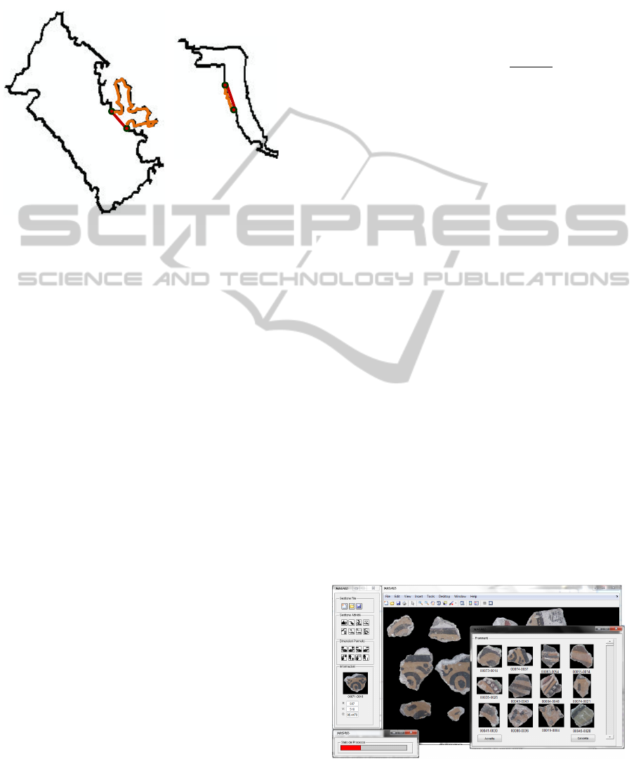
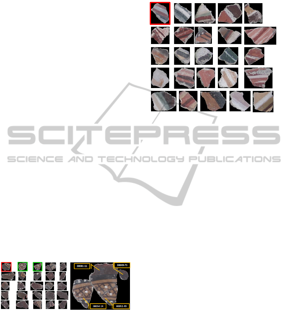
Fig. 9, illustrating a shape-based query.
Lack of information about the “real” solution to
this jigsaw puzzle makes it impossible to obtain an
objective measure of the solution obtained by using
the system in this real-world case, but a qualitative
assessment of its effectiveness is possible. Detailed
feedback from the end users confirmed the substantial
usefulness of such a system.
Figure 8: A query, its result, and a partial reconstruction
made from some of the fragments returned.
In Fig. 8, each label has two values. The first is
the tray where the fragment lies, while the second is
the serial number inside that tray. As the illustration
shows, it is not uncommon for pieces close to each
other in the original picture to end up in quite distant
trays when they are picked up from the original site
or during cataloging.
Figure 9: Query by shape: strips.
5 CONCLUSIONS
MOSAIC (Multi-Object Segmentation for Assisted
Image reConstruction) is a system for the computer
aided reconstruction of pictorial artworks from their
fragments. The fragments are cataloged and indexed
based on relevant features such as color and shape.
Queries can be formulated through the GUI by select-
ing a fragment or a single shape represented on a frag-
ment. The results, sorted by similarity, provide can-
didates for puzzle solving in the area of the relevant
fragment. This can speed up the process significantly
and improve the quality of the reconstruction. The
system has been tested first via computer simulation
in a setting where the solution was known a priori,
and later in a real world situation, where the solution
was unknown. Domain experts have provided pre-
cious feedback for tuning the system; future work is
planned involving more detailed interaction with ar-
chaeologists and cultural heritage operators to better
understand their needs and offer improved support.
REFERENCES
Birchfield, S. T. and Rangarajan, S. (2005). Spatiograms
versus histograms for region-based tracking. In IEEE
Conference on Computer Vision and Pattern Recogni-
tion (CVPR), pages 0–0.
Brown, B., Laken, L., Dutr
´
e, P., Gool, L. V., Rusinkiewicz,
S., and Weyrich, T. (2010). Tools for virtual re-
assembly of fresco fragments. In Proceedings of the
7th International Conference on Science and Technol-
ogy in Archaeology and Conservations, pages 1–10.
SCITEPRESS.
Brown, B., Toler-Franklin, C., Nehab, D., Burns,
ICPRAM2015-InternationalConferenceonPatternRecognitionApplicationsandMethods
106

M., Dobkin, D., Vlachopoulos, A., Doumas, C.,
Rusinkiewicz, S., and Weyrich, T. (2008). A sys-
tem for high-volume acquisition and matching of
fresco fragments: Reassembling theran wall paint-
ings. ACM Transactions on Graphics (Proc. SIG-
GRAPH), 27(3):1–10.
Chung, M. G., Fleck, M., and Forsyth, D. (1998). Jigsaw
puzzle solver using shape and color. In Proceedings of
the 4th International Conference on Signal Processing
(ICSP ’98), volume 2, pages 877–880.
Comaniciu, D. and Meyer, P. (2002). Mean shift: A robust
approach toward feature space analysis. IEEE Trans-
actions on Pattern Analysis and Machine Intelligence
(PAMI), 24(5):603–619.
Freeman, H. and Garder, L. (1964). Apictorial jigsaw puz-
zles: The computer solution of a problem in pattern
recognition. IEEE Transactions on Electronic Com-
puters, 2(EC-13):118–127.
Hu, M. (1962). Visual pattern recognition by moment in-
variants. IRE Trans. Inf. Theor., IT-8:179–187.
Mercimek, M. and Mumcu, K. G. T. V. (2005). Real
object recognition using moment invariants. Sad-
hana, Academy Proceedings in Engineering Science,
30(6):765–775.
Papaodysseus, C., Panagopoulos, T., and Exarhos, M.
(2002). Contour-shape based reconstruction of frag-
mented, 1600 bc wall paintings. IEEE Transactions
on Signal Processing, 6(50):1277–1288.
Sagiroglu, M. and Ercil, A. (2006). A texture based match-
ing approach for automated assembly of puzzles. In
Proceedings of the 18th International Conference on
Pattern Recognition (ICPR ’06), pages 1036–1041.
Multi-ObjectSegmentationforAssistedImagereConstruction
107
