
Improvement of Phase Unwrapping Algorithms by Epipolar Constraints
Johannes K
¨
ohler, Jan C. Peters, Tobias N
¨
oll and Didier Stricker
German Research Center for Artificial Intelligence, Trippstadter Str. 122, 67663 Kaiserslautern, Germany
Keywords:
Structured Light, Fringe Projection, Phase Shifting, Phase Unwrapping.
Abstract:
Phase unwrapping remains a challenging problem in the context of fast 3D reconstruction based on structured
light, in particular for objects with complex geometry. In this paper we suggest to support phase unwrapping
algorithms by additional constraints induced by the scanning setup. This is possible when at least two cameras
are used, a likely case in practice. The constraints are generalized for two or more cameras by introducing the
concept of a candidate map. We claim that this greatly reduces the complexity for any subsequent unwrapping
algorithm, their performance is thereby strongly increased. We demonstrate this by exemplarily integrating
the candidate map into a local path following and a global minimum norm unwrapping method.
1 INTRODUCTION
Phase shifted structured light is a well known and
widely used method in the field of 3D reconstruc-
tion. In this technique, a linear phase function is en-
coded by shifted sine waves and the resulting fringe
patterns are projected onto an object. If these pro-
jections are recorded by a camera, the corresponding
phase values can be recovered from the captured im-
ages. The resulting phase images induce pixel-wise
correspondences of very high quality among all in-
volved devices. These correspondences then can be
used for depth recovery. One of the biggest advan-
tages of phase shifting is its robustness towards the
projector’s narrow depth of field. The projected si-
nusoidal fringe patterns can still be robustly decoded
even if they are out of the projector’s focus range.
However, the desired phase function can only be
recovered modulo-2π. This is an inevitable con-
sequence of the involved trigonometric functions,
whose inverse functions are always restricted to the
principal branch. Phase unwrapping denotes the res-
olution of these ambiguities (Figure 1).
Although this problem has been studied for
decades (Gorthi and Rastogi, 2010), a fully robust
and reliable solution has yet to be found for a sin-
gle frequency level. A successful unwrapping heavily
depends on the object scanned and is particularly dif-
ficult near depth discontinuities. Most everyday ob-
jects are not convex, depth maps of the corresponding
object consequently will contain such discontinuities
(Figure 2 (a)). Perspective projection causes unrelated
(a) (b)
(c) (d)
Figure 1: Individual steps for transmitting a phase from the
projector to a camera. (a) The projector’s phase before si-
nusoidal encoding into a fringe pattern. (b) Projected fringe
pattern. (c) Wrapped phase recovered from multiple fringe
patterns captured by a camera. (d) Unwrapped phase.
phase intervals to seamlessly blend into each other at
such regions, which poses a great challenge to phase
unwrapping algorithms (Figure 2 (b)). The transition
can be more or less smooth, which is very hard to de-
tect.
In this paper we follow the recent trend to uti-
472
Köhler J., Peters J., Nöll T. and Stricker D..
Improvement of Phase Unwrapping Algorithms by Epipolar Constraints.
DOI: 10.5220/0005271404720479
In Proceedings of the 10th International Conference on Computer Vision Theory and Applications (VISAPP-2015), pages 472-479
ISBN: 978-989-758-091-8
Copyright
c
2015 SCITEPRESS (Science and Technology Publications, Lda.)

(a) (b)
Figure 2: (a) Prominent foreground/background discontinu-
ity (the green line separates foreground (object) and back-
ground (wall). Two exemplary parts that belong to the same
wrap count (i.e. to the same stripe) are colored red. (b)
Stripes with different wrap counts seamlessly blending into
each other (red) at a depth discontinuity (enclosed by blue
lines).
lize the geometry of multiple cameras for unwrapping
(Br
¨
auer-Burchardt et al., 2008; Br
¨
auer-Burchardt
et al., 2011; Br
¨
auer-Burchardt et al., 2013; Garcia
and Zakhor, 2012). In these publications, the epipo-
lar geometry of two cameras was used to constrain
the potential unwrapping possibilities. However, the
epipolar geometry alone is not sufficient for unwrap-
ping, many ambiguities remain and further steps are
necessary. In this paper, we propose a more general
approach to use the epipolar geometry. We generalize
its use to more than two cameras and introduce the
candidate map, which stores all geometrically feasi-
ble unwrapping possibilities for a single camera. In
contrast to state of the art methods, we do not focus
on a single method to resolve the remaining ambigu-
ities. Instead, we suggest to use the candidate map
as an appropriate support for any classic phase un-
wrapping algorithm. The candidate map can drasti-
cally improve their performance, we demonstrate this
by including it into two exemplary state of the art un-
wrapping methods.
2 RELATED WORK
Existing phase unwrapping approaches can be
roughly grouped into temporal and spatial methods.
Temporal methods use additional patterns to remove
the ambiguity. All temporal methods have in com-
mon, that the additional patterns encode the period
of the desired phase. (Wang et al., 2010) proposes
sinusoidal patterns with different frequencies for this.
The method starts with a phase function whose encod-
ing yields no wrapping but poor phase quality. The
frequency is consecutively increased while the wrap-
ping is resolved using the previous levels. With the
correct frequency gain, this method yields correctly
unwrapped phases even for objects with many dis-
continuities and has the same advantages than phase
shifting itself. Other authors propose binary codes for
this task (Bergmann, 1995). Temporal methods are
fully local, i.e. the unwrapping decision for a single
pixel does not depend on his neighbors and are thus
robust even for complex objects with many depth dis-
continuities. However, they require a large amount
of additional images to be captured, which might not
be possible in application domains such as real time
scanning.
Spatial methods require less projected patterns
and try to unwrap the phase using neighborhood in-
formation. Existing spatial approaches can be roughly
grouped into two categories: Path following and min-
imum norm.
Path following methods (Goldstein et al., 1988;
Herr
´
aez et al., 2002; Abdul-Rahman et al., 2007; Lof-
feld et al., 2008; Martinez-Espla et al., 2009) start at
at a given pixel and unwrap the phase along a path
in the image by adding or subtracting multiples of 2π
to the current pixel’s phase value. The path to follow
can be fixed or dynamically guided by a phase quality
measure. Algorithms of this kind are also called local
methods, since at every step they just inspect pixels
near the current position.
In contrast to this, minimum norm methods
(Ghiglia and Romero, 1996; Costantini, 1998; Dias
and Leito, 2002; Bioucas-Dias and Valado, 2007)
globally minimize an unwrapping cost function de-
fined for each pair of neighboring pixels. Both ap-
proaches suffer from inaccuracies at depth discontinu-
ities, where unrelated phase intervals can seamlessly
blend into each other (Figure 2).
The aforementioned methods are purely image
based and rely on a single viewpoint. Several authors
recently proposed to use two viewpoints and their cor-
responding epipolar geometry for phase unwrapping.
This allows to deduce local (i.e. pixelwise) contraints.
Common to all methods is the fact, that epipolar con-
straints alone are not sufficient for a correct unwrap-
ping, many ambiguities remain. It is thus important
to apply additional steps for computing the desired
phase. (Br
¨
auer-Burchardt et al., 2008) were the first
to use epipolar geometry. They use a disparity map
to resolve the remaining ambiguities, which is also
related to the epipolar geometry. In their follow up
paper (Br
¨
auer-Burchardt et al., 2011), they use com-
binatorial considerations, but unwrapping ambiguities
can still remain. (Br
¨
auer-Burchardt et al., 2013) tries
to resolve the ambiguities with a special hardware
and parameter arrangement. However, this reduces
the generality of the hardware setup, these restrictions
ImprovementofPhaseUnwrappingAlgorithmsbyEpipolarConstraints
473

might thus not be admissible in every scenario. (Gar-
cia and Zakhor, 2012) also use a stereo camera setup
and propose two approaches to resolve the remaining
ambiguities. The temporal approach is not relevant in
our context, as we focus on static scene reconstruc-
tion. The energy minimization approach can be con-
sidered as special case of our proposed framework.
In contrast to state of the art methods, which usu-
ally use only two cameras, we generalize the use of
epipolar geometry to n cameras by introducing the
candidate map in this paper. The candidate map does
not unambiguously unwrap the phase, but it strongly
constrains the available possibilities. We believe that
existing unwrapping methods can be used to achieve
this and thus suggest to use the candidate map as rea-
sonable preprocessing step for any classical phase un-
wrapping method.
3 PHASE GENERATION
In the context of this paper, phases are generated with
phase shifted structured light. A phase is thus defined
in the image plane of a projector as a linear function
Φ(x, y) ∈ [0..2πN] (Figure 1 (a)). Φ can be projected
onto an object and recovered from the point of view
of a camera by encoding it with a sine or cosine func-
tion and shifting it K times. This results in shifted
fringe patterns captured in K camera images, an ex-
emplary camera image with a pattern projected onto
an object is illustrated in Figure 1 (b). For each pixel
it is then possible to compute tan(φ) using e.g. (Guo
et al., 2007), where φ is the desired object phase seen
from the respective camera. The tangent results from
the periodicity of the involved trigonometric functions
and the inverse tangent thus does not yield φ, but the
wrapped object phase ψ = φ mod 2π (Figure 1 (b)).
Note that the parameter N defines the amount of peri-
ods and thus also the wrap count of φ.
Without loss of generality, we restrict Φ to have a
constant gradient ∇Φ = d, d ∈ R
2
. This simply con-
strains the isocurves of Φ to be straight lines, as op-
posed to e.g. (Peng and Gupta, 2008). For d = (1, 0),
Φ would thus correspond to e.g. Figure 1 (a) and we
would project vertical fringes. We use this property in
Section 4 to relate the phase to the camera geometry.
4 CANDIDATE MAP
GENERATION
Depth reconstruction based on structured light can
be accomplished with a video projector and a single
camera. If more cameras are present, they naturally
restrict the unwrapping possibilities. In practice it is
likely to have more than one camera, because trian-
gulation with only cameras does not require a gamma
calibration (Guo et al., 2004) in contrast to triangula-
tion with a camera and the projector (Han and Huang,
2009).
In the following, we consider a scanning setup
with one projector and n ≥ 2 cameras and derive
phase constraints from the devices’ epipolar geome-
try. Our method requires only the fundamental ma-
trix, it is thus not stringently required to fully calibrate
the cameras by estimating their poses and intrinsic pa-
rameters (focal length, principal point and distortion
coefficients). However, a structured light scanner is
usually calibrated and especially a prior calibration of
the camera’s distortion coefficients and undistortion
of the respective images greatly improves the accu-
racy of the method. For an uncalibrated setup, the
fundamental matrix is easily computed from 2D cor-
respondences (Hartley and Zisserman, 2004).
The method sketched in Section 3 yields a
wrapped object phase ψ
i
for each camera (Figure
1 (c)). For every wrapped phase value ψ
i
(x, y) ∈
[0..2π] there is exactly one w ∈ {0..N − 1} such that
ψ
i
(x, y) + w · 2π = φ
i
(x, y). w is the desired period or,
in other words, the index of the correct stripe (Figure
1 (c)). It adds the multiple of 2π required for unwrap-
ping and we consider it as the wrap count.
The task of each unwrapping algorithm thus is to
find the correct w for each pixel of ψ
i
. To formally
handle all possible values of w, we define the candi-
date map C
i
:
C
i
: N
2
→ P {0, ..., N − 1} (1)
where P is the power set operator. For each pixel of
a primary view there are N unwrapping possibilities
and the candidate map stores a subset of geometri-
cally feasible wrap counts for each pixel: C
i
(x, y) ⊆
{0,...,N − 1}.
C
i
is called consistent at position (x,y), if the cor-
rect wrap count w is present in C
i
(x, y). Pixels (x, y)
with |C
i
(x, y)| = 1 are called singletons. If a singleton
is consistent, it correctly unwraps the phase without
ambiguities.
Since the correct unwrapping must be consistent
among the devices, secondary views can drastically
reduce the feasible amount of unwrapping possibili-
ties |C
i
(x, y)| (Figure 3).
In the following we compute a candidate map C
i
by enforcing epipolar phase consistency among mul-
tiple secondary views. Given n ≥ 2 views, a primary
view i, fundamental matrices F
i j
from the primary
view i to each secondary view j, F
ip
from the primary
view to the projector and F
p j
from the projector to
VISAPP2015-InternationalConferenceonComputerVisionTheoryandApplications
474

primary view (ψ
i
)
projector (Ψ)
secondary view (ψ
j
)
epipolar line l
p
p
i
p
p0
p
j0
p
pN-1
p
jN-1
epipolar line
F
ij
p
i
Figure 3: Geometry of all unwrapping candidates for N =
4. If |ψ
i
(p
i
) − ψ
j
(p
j
k
)| > ε, the corresponding candidate
can be excluded before an unwrapping algorithm is applied
(zoom in for details). At the dotted lines, Ψ = ψ
i
(p
i
).
each secondary view, we can restrict the unwrapping
candidates C
i
(p
i
) for each primary view pixel p
i
by
applying the following steps:
• Compute epipolar line l
p
= F
ip
(p
i
,1)
T
in the pro-
jector image plane. The periods of the projector’s
phase touched by this line are relevant for unwrap-
ping. In Figure 3, all 4 exemplary periods are thus
relevant.
• Compute intersections p
p
0
..p
p
N−1
of l
p
with each
phase isoline corresponding to φ
i
(p
i
). These are
the projector pixels with a phase value of φ
i
(p
i
)
that could have illuminated p
i
.
• Each of these intersections defines a unique point
in a secondary view: We propagate the phase line
intersection points p
p
k
to each secondary view j
by computing the intersection points p
j
k
of the
epipolar line pairs (F
i j
(p
i
,1)
T
,F
p j
(p
p
k
,1)
T
). The
resulting pixels potentially perceive the same ob-
ject point and thus should have the same phase
value than the primary view (ψ
i
(p
i
)).
• if |ψ
i
(p
i
) − ψ
j
(p
j
k
)| < ε, it can be assumed, that
the secondary view j perceives the same wrapped
phase value. Due to occlusions, this will not hold
for all secondary views. We thus add the cor-
responding wrap count to C
i
(x, y), if this condi-
tion holds for m ≤ n − 1 secondary views, which
means that m secondary views agree on the per-
ceived phase value.
Remark: It is required for numerical stability, that
the angle enclosed by a phase line and an epipolar line
is not too low. As a rule of thumb for two cameras
and a projector setup, the devices should be placed on
a straight line that has ∇Φ as directional vector. E.g.
for cameras placed on a table to the left and right of a
projector such that the image planes are parallel, the
epipolar lines are parallel to the image planes’ x-axis.
A phase with ∇Φ = (1, 0) would then be optimal, as
the phase’s isolines and the epipolar lines are perpen-
dicular.
5 PHASE UNWRAPPING
In general, the performance of most phase unwrap-
ping algorithms can be greatly enhanced by augment-
ing them with a candidate map. This does not only re-
duce the amount of unwrapping possibilities per pixel
but can also directly constrain the starting pixels to
the correct phase value. This is in fact a serious dis-
advantage shared by many unwrapping methods: The
unwrapped phase produced by the respective algo-
rithm might be consistent in itself but shifted with
respect to the original phase projected onto the ob-
ject. This is caused by the fact that a wrap count
w needs to be assigned to the starting pixels for ini-
tialization. Subsequent pixels are unwrapped relative
to this w. Since an initial w cannot be correctly de-
termined without additional information it must later
be corrected, which might not always be possible.
The singletons of the candidate map, which are un-
wrapped correctly, implicitly solve this problem. In
the following, we sketch how to integrate the candi-
date map into a local path following algorithm and
outline a new global minimum norm algorithm based
on graph labeling.
5.1 Local Unwrapping by Region
Growing
As an exemplary local unwrapping algorithm we
choose the region growing method of (Xu and Cum-
ming, 1999). This algorithm starts growing regions
from multiple pixels of high data quality and prop-
agates the phase along paths with high unwrapping
confidence. A pixel p is unwrapped using a weighted
mean of predictions based on extrapolations of neigh-
bouring pixels that are already unwrapped in a 5x5
window centered at p. The process is illustrated in
Figure 4. Predictions are made following K straight
lines originating from p. If in a direction k there is
only one unwrapped pixel, the corresponding predic-
tion is constant and the associated weight is set to 0.5.
In case there are two already unwrapped pixels along
the prediction line, a linear extrapolation is used and
w
k
= 1 since these predictions are more reliable than
the constant ones. Then a composite prediction
˜
φ(p)
is formed as weighted average of the individual pre-
dictions. This composite prediction is used in an un-
wrapping attempt for p:
φ(p) = Ψ(p)+ 2πs with s =
˜
φ(p) − Ψ(p)
2π
(2)
ImprovementofPhaseUnwrappingAlgorithmsbyEpipolarConstraints
475
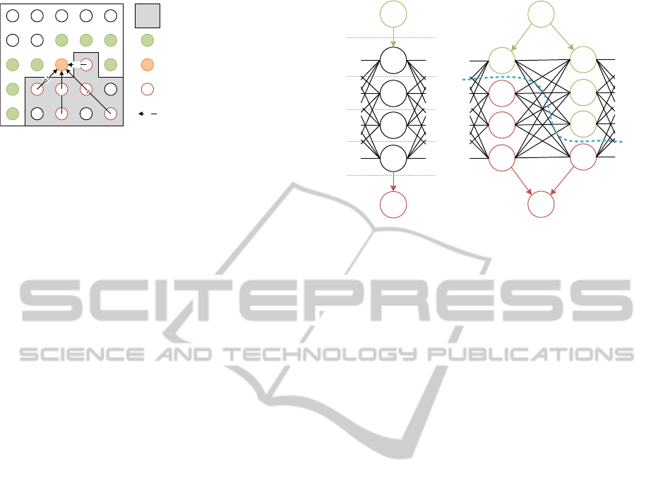
0.5
1
unwrapped region
growth pixels
currently unwrapped pixel
pixels used for unwrapping
0.5
prediction lines with weights
Figure 4: Unwrapping by region growing and phase predic-
tion. This figure is based on an illustration in the original
paper (Xu and Cumming, 1999).
The operator [·] denotes rounding to the nearest in-
teger. The essence of this approach is the same as for
the level based temporal unwrapping, note the strik-
ing similarity of Equation 2 and Equation 7 of (Wang
et al., 2010). However, the wrap count in our case is
estimated from the neighborhood instead from addi-
tional patterns. The unwrapping is accepted after ad-
ditional reliability checks, please refer to the original
paper for more details.
Although the method starts from multiple local
positions, we found that it cannot fully cope with
discontinuities where the phase values with different
wrap counts seamlessly blend into each other (Figure
1 (d)). Integration of the candidate map can resolve
this and is straightforward: We start growing regions
only from singletons, the phase is thus directly un-
wrapped without having to deal with the relative shift
problem. In addition to the original reliability checks,
we allow an unwrapping at p only, if the correspond-
ing wrap count is found in the candidate map. In our
evalutaion we show that this greatly stabilizes the un-
wrapping process.
5.2 Global Unwrapping by Graph
Labeling
The application of graph cut based optimization to la-
beling problems had a large impact on image process-
ing during the last decade (Kolmogorov and Zabin,
2004; Boykov et al., 2001). Given an undirected
graph G = (V, E) and a set of labels L = {l
1
,..., l
N
}, a
(graph) labeling of G is a mapping ` : V → L. Further-
more there are weights placed on vertices and edges
of the graph. First order weighting functions are de-
fined for the vertices and depend on the label of the
respective vertex. Second order weighting functions
are defined for each edge, they depend on the weights
of the associated vertices. The ultimate goal then is
to compute a labeling of the graph that minimizes the
sum of all weights.
The graph labeling technique was also used for
phase unwrapping (Bioucas-Dias and Valado, 2007).
s
t
4
3
2
1
0
(a)
s
t
u
v
(b)
Figure 5: Parts of the graph G
0
for N = 5. Left: Representa-
tives of a single pixel from G. The dashed lines illustrate the
possible cuts and the associated wrap-counts. Right: Repre-
sentatives of two pixels u,v and their connections. The blue
dashed line is a possible graph-cut, the vertices are colored
according to the side of the cut they are on.
It relates to unwrapping in the following way: Each
pixel yields a vertex and neighboring pixels are con-
nected by an edge which results in a graph G. Each
w ∈ {0..N − 1} represents a label and each pixel of a
wrapped phase is unwrapped by labeling it with one
w. The costs for a certain labeling are defined only
by second order weighting functions for each pair of
neighboring pixels. Minimization can then be accom-
plished using a graph cut. Since graph cuts optimize
binary labeling problems however, we follow the “k
to 2” method of (Schlesinger and Flach, 2006) to
transform our N-ary labeling problem to a binary one.
In the corresponding new graph G
0
, each vertex (i.e.
each pixel) of the old one is represented by N − 1 ver-
tices. Where there is an edge (u,v) in G, the represen-
tatives of u and v are fully interconnected in G
0
. More-
over, there are two special vertices s and t in G
0
which
provide the source and sink for the graph-cut calcula-
tion and are connected to the first and last representa-
tives of each pixel, respectively. The spaces between
representatives themselves and between them and s
and t stand for the labels or here wrap-counts which
are identified with possible graph-cuts in G
0
. The sit-
uation is illustrated in Fig. 5.
Our cost function for the edges is
f (p
0
, p
1
,w
0
,w
1
) = k2πw
0
+ψ(p
0
)−(2πw
1
+ψ(p
1
))k
(3)
for a wrapped phase ψ, pixels p
0
and p
1
and wrap
counts w
0
and w
1
. This function in particular pe-
nalizes unwrapping over discontinuities, where |w
0
−
w
1
| > 1.
After computing a min-cut on G
0
the wrap-count
for each pixel is determined by assigning each repre-
VISAPP2015-InternationalConferenceonComputerVisionTheoryandApplications
476

(a) (b)
Figure 6: The two objects used for evaluation. “Krusty” is
a gum figure with smooth geometry, it yields rather smooth
phases. The “Allegorie” is mostly made from metal and
marble, it yields rather noisy phases. Moreover, its highly
non-convex nature yields many self-occlusions. The respec-
tive discontinuities make the phases very hard to unwrap.
sentative the side of the cut it is on and by finding the
gap with the transition from source to sink, as indi-
cated in Figure 5. However, the sheer size of the graph
results in high memory consumption and high com-
putation time. Especially for high camera resolutions,
the computation of a min-cut becomes intractable.
The advantage of this method is the straightfor-
ward application of the candidate map: The struc-
ture of the candidate map is directly reflected in the
graph and all geometrically unfeasible labelings can
be omitted. This relaxes the problems mentioned
above: The number of representatives for each pixel
and thus the memory consumption is drastically re-
duced, which also speeds up the process considerably.
Similar to the region growing approach, singletons
fix the relative shift problem in this context, too. In
our evaluation, we apply the method to 15 megapixel
phase images, which is not possible without the can-
didate map.
6 RESULTS
To prove the validity of the suggested methods, we
apply them to scans of two objects with very different
texture and geometric complexity (Figure 6). The first
object (“Krusty”) is a figurine made of gum. Its color-
ing is simple, every region features one hue. The ob-
ject geometry is also quite simple, there are only few
rough edges and the surface is mostly smooth. From
most viewpoints, it yields phases with low noise, that
are rarely disrupted by discontinuities. The second
object (“Allegorie”) is a statue made from different
materials, mostly brass and marble. These materials
produce a phase with more noise. The complex geom-
etry causes many self-occlusions and depth disconti-
nuities from most view points, which makes the phase
significantly harder to unwrap.
Both objects were scanned with multi-frequency
phase shifting with a setup of one Sanyo
R
Z 4100
projector (1920x1080) and seven Canon
R
EOS
R
500D cameras (4752x3168). We used five frequency
levels N = {1, 5, 11, 27, 91} with three shifts for the
first four levels and ten shifts for the fifth level for bet-
ter noise reduction. With these parameters, the multi-
frequency unwrapping algorithm of (Wang et al.,
2010) is able to correctly unwrap each level, we thus
use this phase as ground truth. Note that this unwrap-
ping algorithm requires substantially more input im-
ages due to the additional levels, which is intractable
in some application domains such as real time scan-
ning. In all experiments, the amount of required sec-
ondary views (m) is two.
Figure 7 (top row) shows the candidate maps and
the results of the proposed unwrapping algorithms for
N = 27 and N = 91. For both objects, large parts
of the candiate maps are filled with singletons. As
one would expect, the amount of candidates is larger
for N = 91. The second row of Figure 7 shows the
results of the region growing algorithm without can-
didate map. Since the algorithm does not know the
correct phase period at its starting pixels, it assigns
a fixed w. Regions blending into each other are then
merged, i.e. the wrap count of one unwrapped region
is shifted to be consistent with the other region. How-
ever, consistent merging is not possible anymore as
soon as an unwrapping path crosses a depth discon-
tinuity that has a smooth phase (Figure 1 (d)). This
causes multiple self-consistent patches, whose phase
is shifted (unicolored, non-green regions). An aug-
mentation of this algorithm with the candidate map
almost fully resolves this problem (Figure 7, third
row). This is a remarkable result, in particular for the
“Allegorie” dataset, whose complex geometry with
many depth discontinuities yield phases that are very
hard to unwrap. Since the unwrapping is restricted
to |C
i
(p)| > 0 however, the unwrapped regions are
smaller for both objects. This could be improved by
applying classic approaches to regions with |C
i
(p)| =
0 after unwrapping with the candidate map, if the cor-
responding region is connected to an unwrapped part.
At N = 91, the performance of the augmented algo-
rithms is worse than at N = 27, but still better than
ImprovementofPhaseUnwrappingAlgorithmsbyEpipolarConstraints
477
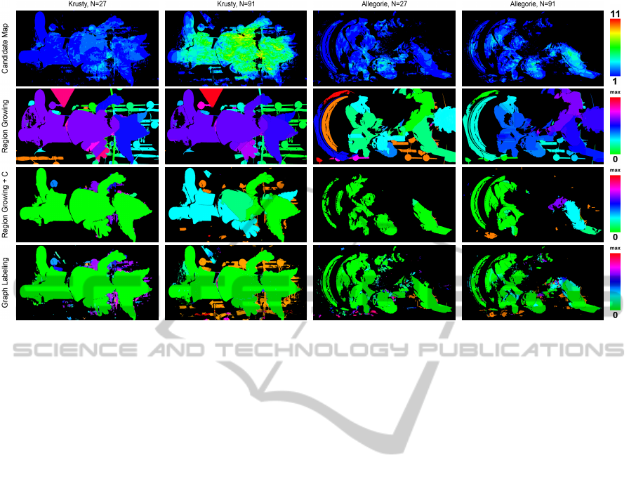
Figure 7: Candidate maps and results of the enhanced unwrapping algorithms. For the unwrapping results (row 2-4) we
visualize the period difference to the reference phase. Green corresponds to correct unwrapping, red to the highest measured
difference for this dataset. Everything but green yields wrong depth values.
without the candidate map. In case of the gum figure,
this is caused by the presence of only few singletons,
that are distributed along the border. In this region,
the surface normal is almost orthogonal to the view
direction and the reliability of C
i
decreases. The same
holds for the arm region of the “Allegorie” dataset.
The globally operating graph labeling algorithm
in general performs significantly better than the lo-
cal path integration method. It also handles the few
singletons at N = 91 well and propagates the correct
phase over almost the full objects. In theory, the graph
labeling method can also be applied without the can-
didate map. In this case, each label is available per
pixel and the relative phase position is fixed by as-
signing a fixed label to some pixel(s). We tried this
but memory consumption and processing time of this
approach are unfeasible.
7 CONCLUSION
In this paper we proposed a general approach for us-
ing the epipolar geometry of multiple cameras in the
context of phase unwrapping. We introduced the con-
cept of the candidate map to aggregate all geometri-
cally feasible unwrapping possibilities. In contrast to
state of the art methods, we understand the candidate
map as a preprocessing step, that can support any sub-
sequent phase unwrapping algorithm.
The effect of the candidate map was illustrated by
augmenting two exemplary unwrapping methods: A
local path following and a global minimum norm ap-
proach. Our results illustrate, that both algorithms
greatly benefit from the additional constraints pro-
vided by our candidate map. This is particularly im-
portant for application domains that require fast ac-
quisition speed and thus a low amount of captured
images such as real time scanning. Robust, temporal
unwrapping cannot be applied here. Together with the
fact that additional cameras also relax the need for a
gamma calibration we thus suggest to use at least two
cameras for such a respective system.
ACKNOWLEDGEMENTS
The work presented in this paper has been partially
funded by the project DENSITY (01IW12001).
REFERENCES
Abdul-Rahman, H., Gdeisat, M., Burton, D., Lalor, M., Lil-
ley, F., and Moore, C. (2007). Fast and Robust Three-
Dimensional Best Path Phase Unwrapping Algorithm.
Applied Optics, 46(26):6623–6635.
Bergmann, D. (1995). New approach for automatic surface
reconstruction with coded light. volume 2572.
Bioucas-Dias, J. M. and Valado, G. (2007). Phase unwrap-
VISAPP2015-InternationalConferenceonComputerVisionTheoryandApplications
478

ping via graph cuts. IEEE Transactions on Image Pro-
cessing, 16(3):698–709.
Boykov, Y., Veksler, O., and Zabih, R. (2001). Fast approxi-
mate energy minimization via graph cuts. IEEE Trans.
Pattern Anal. Mach. Intell., 23(11):1222–1239.
Br
¨
auer-Burchardt, C., K
¨
uhmstedt, P., and Notni, G. (2013).
Phase unwrapping using geometric constraints for
high-speed fringe projection based 3d measurements.
volume 8789.
Br
¨
auer-Burchardt, C., Munkelt, C., Heinze, M., K
¨
uhmstedt,
P., and Notni, G. (2008). Phase unwrapping in fringe
projection systems using epipolar geometry. In Blanc-
Talon, J., Bourennane, S., Philips, W., Popescu, D.,
and Scheunders, P., editors, Advanced Concepts for
Intelligent Vision Systems, number 5259 in Lecture
Notes in Computer Science, pages 422–432. Springer
Berlin Heidelberg.
Br
¨
auer-Burchardt, C., Munkelt, C., Heinze, M., K
¨
uhmstedt,
P., and Notni, G. (2011). Using geometric constraints
to solve the point correspondence problem in fringe
projection based 3d measuring systems. In Maino,
G. and Foresti, G., editors, Image Analysis and Pro-
cessing ICIAP 2011, volume 6979 of Lecture Notes
in Computer Science, pages 265–274. Springer Berlin
Heidelberg.
Costantini, M. (1998). A novel phase unwrapping method
based on network programming. Geoscience and Re-
mote Sensing, IEEE Transactions on, 36(3):813–821.
Dias, J. M. B. and Leito, J. M. N. (2002). The zm algo-
rithm: a method for interferometric image reconstruc-
tion in sar/sas. IEEE Transactions on Image Process-
ing, 11(4):408–422.
Garcia, R. and Zakhor, A. (2012). Consistent stereo-assisted
absolute phase unwrapping methods for structured
light systems. Selected Topics in Signal Processing,
IEEE Journal of, 6(5):411–424.
Ghiglia, D. C. and Romero, L. A. (1996). Minimum Lp-
norm two-dimensional phase unwrapping. J. Opt. Soc.
Am. A, 13(10):1999–2013.
Goldstein, R. M., Zebker, H. A., and Werner, C. L. (1988).
Satellite radar interferometry: Two-dimensional phase
unwrapping. Radio Science, 23(4):713–720.
Gorthi, S. S. and Rastogi, P. (2010). Fringe projection tech-
niques: whither we are? Optics and Lasers in Engi-
neering, 48:133–140.
Guo, H., He, H., and Chen, M. (2004). Gamma correction
for digital fringe projection profilometry. Appl. Opt.,
43(14):2906–2914.
Guo, H., Zhao, Z., and Chen, M. (2007). Efficient itera-
tive algorithm for phase-shifting interferometry. Op-
tics and Lasers in Engineering, 45(2):281–292.
Han, X. and Huang, P. (2009). Combined stereovision and
phase shifting method: a new approach for 3d shape
measurement. volume 7389, pages 73893C–73893C–
8.
Hartley, R. I. and Zisserman, A. (2004). Multiple View Ge-
ometry in Computer Vision. Cambridge University
Press, ISBN: 0521540518, second edition.
Herr
´
aez, M. A., Burton, D. R., Lalor, M. J., and
Gdeisat, M. A. (2002). Fast two-dimensional phase-
unwrapping algorithm based on sorting by reliabil-
ity following a noncontinuous path. Applied Optics,
41(35):7437–7444.
Kolmogorov, V. and Zabin, R. (2004). What energy func-
tions can be minimized via graph cuts? Pattern Anal-
ysis and Machine Intelligence, IEEE Transactions on,
26(2):147–159.
Loffeld, O., Nies, H., Knedlik, S., and Wang, Y. (2008).
Phase unwrapping for sar interferometry - a data fu-
sion approach by kalman filtering. IEEE T. Geo-
science and Remote Sensing, 46(1):47–58.
Martinez-Espla, J. J., Martnez-Marn, T., and Lopez-
Sanchez, J. M. (2009). A particle filter approach for
insar phase filtering and unwrapping. IEEE T. Geo-
science and Remote Sensing, 47(4):1197–1211.
Peng, T. and Gupta, S. K. (2008). Algorithms for generat-
ing adaptive projection patterns for 3d shape measure-
ment. Journal of Computing and Information Science
in Engineering, 8(3):031009.
Schlesinger, D. and Flach, B. (2006). Transforming an ar-
bitrary minsum problem into a binary one. Technical
Report TUD-FI06-01, Technische Universit
¨
at Dres-
den.
Wang, Z., Nguyen, D. A., and Barnes, J. C. (2010). Some
practical considerations in fringe projection profilom-
etry. Optics and Lasers in Engineering, 48(2):218 –
225. Fringe Projection Techniques.
Xu, W. and Cumming, I. (1999). A region-growing algo-
rithm for InSAR phase unwrapping. IEEE Transac-
tions on Geoscience and Remote Sensing, 37(1):124–
134.
ImprovementofPhaseUnwrappingAlgorithmsbyEpipolarConstraints
479
