
Resource Allocation in SVD-assisted Broadband MIMO Systems Using
Polynomial Matrix Factorization
André Sandmann, Andreas Ahrens and Steffen Lochmann
Hochschule Wismar, University of Technology, Business and Design, Philipp-Müller-Straße 14, 23966 Wismar, Germany
Keywords:
Multiple-Input Multiple-Output System, Singular-Value Decomposition, Polynomial Matrix Factorization,
Bit Allocation, Power Allocation, Wireless Transmission.
Abstract:
Removing channel interference in broadband multiple-input multiple-output (MIMO) systems is a task which
can be solved by applying a spatio-temporal vector coding (STVC) channel description and using singular
value decomposition (SVD) in combination with signal pre- and post-processing. In this contribution a poly-
nomial matrix factorization channel description in combination with a specific SVD algorithm for polynomial
matrices is analyzed and compared to the commonly used STVC SVD. This comparison points out the analo-
gies and differences of both equalization methods. Furthermore, the bit error rate (BER) performance is eval-
uated for two different channel types and is optimized by applying bit-allocation schemes involving a power
loading strategy. Our results, obtained by computer simulation, show that polynomial matrix factorization
such as polynomial matrix SVD could be an alternative signal processing approach compared to conventional
SVD-based MIMO approaches in frequency-selective MIMO channels.
1 INTRODUCTION
The strategy of placing multiple antennas at the trans-
mitter and receiver sides, well-known as multiple-
input multiple-output (MIMO) system, improves the
performance of wireless systems by the use of the
spatial characteristics of the channel. MIMO systems
have become the subject of intensive research over the
past 20 years as MIMO is able to support higher data
rates and shows a higher reliability than single-input
single-output (SISO) systems. Singular-value decom-
position (SVD) is well-established in MIMO signal
processing where the whole MIMO channel is trans-
ferred into a number of weighted SISO channels. The
unequal weighting of the SISO channels has led to
intensive research to reduce the complexity of the re-
quired bit- and power-allocation techniques (Ahrens
and Lange, 2008; Ahrens and Benavente-Peces, 2009;
Kühn, 2006). The polynomial matrix singular-value
decomposition (PMSVD) is a signal processing tech-
nique which decomposes the MIMO channel into
a number of independent frequency-selective SISO
channels so called layers (McWhirter et al., 2007).
The remaining layer-specific interferences as a result
of the PMSVD-based signal processing can be easily
removed by further signal processing such as zero-
forcing equalization as demonstrated in this work.
The novelty of our contribution is that we demon-
strate the benefits of amalgamating a suitable choice
of MIMO layers activation and number of bits per
layer along with the appropriate allocation of the
transmit power under the constraint of a given fixed
data throughput. Here, bit- and power-loading in
both SVD- and PMSVD-based MIMO transmission
systems are elaborated. Assuming a fixed data rate,
which is required in many applications (e.g., real time
video applications), a two stage optimization process
is proposed. Firstly, the allocation of bits to the num-
ber of SISO channels is optimized and secondly, the
allocation of the available total transmit power is stud-
ied when minimizing the overall bit-error rate (BER)
at a fixed data rate. Our results, obtained by computer
simulation, show that PMSVD could be an alternative
signal processing approach compared to conventional
SVD-based MIMO approaches in frequency-selective
MIMO channels.
The remaining part of this paper is structured as
follows: Section 2 introduces the state of the art SVD-
based MIMO system model. The polynomial ma-
trix singular-value decomposition is analysed in sec-
tion 3. In section 4 the well-know quality criteria is
briefly reviewed and applied to our problem. The pro-
posed power allocation solutions are discussed in sec-
tion 5, while the associated performance results are
317
Sandmann A., Ahrens A. and Lochmann S..
Resource Allocation in SVD-assisted Broadband MIMO Systems Using Polynomial Matrix Factorization.
DOI: 10.5220/0005265403170324
In Proceedings of the 5th International Conference on Pervasive and Embedded Computing and Communication Systems (AMC-2015), pages 317-324
ISBN: 978-989-758-084-0
Copyright
c
2015 SCITEPRESS (Science and Technology Publications, Lda.)

presented and interpreted in section 6. Finally, sec-
tion 7 provides some concluding remarks.
2 STATE OF THE ART
A frequency selective MIMO link, composed of n
T
transmit and n
R
receive antennas is given by
u = H ·c + n . (1)
In (1), c is the (N
T
×1) transmitted data signal vec-
tor containing the complex input symbols transmitted
over n
T
transmit antennas in K consecutive time slots,
i. e., N
T
= K n
T
. The vector u describes the (N
R
×1)
received signal vector, of the length N
R
= (K +L
c
)n
R
,
which is extended if compared to the transmitted sig-
nal vector based on the (L
c
+ 1) non-zero elements
of the resulting symbol rate sampled overall channel
impulse response between the µth transmit and νth re-
ceive antenna. Finally, the (N
R
×1) vector n in (1) de-
scribes the noise term (Ahrens and Benavente-Peces,
2009).
The (N
R
× N
T
) system matrix H of the block-
oriented system model, introduced in (1), results in
H =
H
11
.. . H
1n
T
.
.
.
.
.
.
.
.
.
H
n
R
1
··· H
n
R
n
T
, (2)
and consists of n
R
·n
T
SISO channel matrices H
νµ
(with ν = 1,.. .,n
R
and µ = 1,..., n
T
). The sys-
tem description, called spatio-temporal vector coding
(STVC), was introduced by RALEIGH (Raleigh and
Cioffi, 1998; Raleigh and Jones, 1999). Each of these
matrices H
νµ
with the dimension ((K + L
c
) ×K) de-
scribes the influence of the channel from transmit an-
tenna µ to receive antenna ν including transmit and
receive filtering. The channel convolution matrix H
νµ
between the µth transmit and νth receive antenna is
obtained by taking the (L
c
+ 1) non-zero elements
of resulting symbol rate sampled overall impulse re-
sponse into account and results in
H
νµ
=
h
0
0 0 ··· 0
h
1
h
0
0 ···
.
.
.
h
2
h
1
h
0
··· 0
.
.
. h
2
h
1
··· h
0
h
L
c
.
.
. h
2
··· h
1
0 h
L
c
.
.
. ··· h
2
0 0 h
L
c
···
.
.
.
0 0 0 ··· h
L
c
. (3)
presented and interpreted in section 6. Finally, sec-
c
ℓ,
y
ℓ,
w
ℓ,
p
ξ
ℓ,
Figure 1: Resulting layer-specific SVD-based broad-
band MIMO system model (with 1 2
and
Figure 1: Resulting layer-specific SVD-based broad-
band MIMO system model (with ℓ = 1,2, . ..,L and k =
1,2,. .. ,K).
The removal of the interferences between the dif-
ferent antenna’s data streams, which are introduced
by the non-zero off-diagonal elements of the chan-
nel matrix H, requires appropriate signal processing
strategies. Singular-value decomposition (SVD) can
be considered as a promising solution for transfer-
ring the whole MIMO system into a system with non-
interfering channels, so called layers.
Using SVD the system matrix H can be written as
H = S ·V ·D
H
, where S and D
H
are unitary matrices
and V is a real-valued diagonal matrix of the positive
square roots of the eigenvalues of the matrix H
H
H
sorted in descending order
1
. For removing the inter-
ferences, the MIMO data vector c is now multiplied
by the matrix D before transmission. In turn, the re-
ceiver multiplies the received vector u by the matrix
S
H
. Thereby neither the transmit power nor the noise
power is enhanced given S and D are unitary. The
overall transmission relationship is defined as
y = S
H
(H ·D ·c + n) = V ·c + w. (4)
As a consequence of the processing in (4), the chan-
nel matrix H is transformed into independent, non-
interfering layers having unequal gains.
With the proposed system structure, the SVD-
based equalization leads to different number of
MIMO layers ℓ (with ℓ = 1, 2,. .. ,L) at the time k
(with k = 1,2, .. ., K). Here it is worth noting that
the number of parallel transmission layers L at the
timeslot k is limited by min(n
T
,n
R
). The complex-
value data symbol c
ℓ,k
to be transmitted over the layer
ℓ at the time k is now weighted by the corresponding
positive real-valued singular-value
ξ
ℓ,k
and further
disturbed by the additive noise term w
ℓ,k
.
3 POLYNOMIAL MATRIX
FACTORIZATION
In contrast to the STVC, the polynomial matrix fac-
torization exploits a description of the channel im-
pulse responses in the z-domain. Thus, each fre-
quency selective channel impulse response h
νµ
(k) be-
1
The transpose and conjugate transpose (Hermitian) of
D are denoted by D
T
and D
H
, respectively.
PECCS2015-5thInternationalConferenceonPervasiveandEmbeddedComputingandCommunicationSystems
318

tween the µth transmit and the νth receive antenna of
a (n
R
×n
T
) MIMO system is given by
h
νµ
(z) =
L
c
∑
k=0
h
νµ
[k] z
−k
, (5)
where the underscore denotes a polynomial. Consec-
utively, the broadband MIMO channel is formed by
grouping these impulse responses into the polynomial
channel matrix and thus it can be described as multi-
ple non-polynomial matrices H
k
multiplied with their
respective delay z
−k
as follows
H(z) =
L
c
∑
k=0
H
k
z
−k
H(z) =
h
11
(z) h
12
(z) ··· h
1n
T
(z)
h
21
(z) h
22
(z) ··· h
2n
T
(z)
.
.
.
.
.
.
.
.
.
.
.
.
h
n
R
1
(z) h
n
R
2
(z) ··· h
n
R
n
T
(z)
(6)
where H(z) ∈C
n
R
×n
T
. Using this polynomial descrip-
tion in the z-domain a MIMO system is described in
analogy to (1) by
u(z) = H(z) c(z) + n(z) , (7)
where c(z) is the (n
T
×1) transmit signal vector, u(z)
is the (n
R
×1) receive signal vector and n(z) describes
the additive white Gaussian noise (AWGN) compo-
nent in polynomial notation.
The polynomial channel matrix H(z) can be or-
thogonalized by calculating the polynomial matrix
singular value decomposition (PMSVD) with the help
of the second-order sequential best rotation (SBR2)
algorithm as presented in (McWhirter et al., 2007;
Foster et al., 2010). The decomposition of the polyno-
mial channel matrix results in H(z) = S(z)V(z)
D(z),
where (
·) denotes the para-conjugate operator. The
matrices S(z) ∈C
n
R
×n
R
and
D(z) ∈C
n
T
×n
T
are parau-
nitary matrices and V(z) ∈ C
n
R
×n
T
is assumed to be
a diagonal matrix, because the off-diagonal elements
are negligibly small when the SBR2 algorithm is set
up accordingly. The diagonal matrix has the follow-
ing form (n
T
= n
R
)
V(z) =
v
1
(z) 0 ··· 0
0 v
2
(z) ··· 0
.
.
.
.
.
.
.
.
.
.
.
.
0 0 ··· v
L
(z)
, (8)
where the diagonal polynomial elements are de-
scribed by v
ℓ
(z) =
∑
L
v
k=0
v
ℓ,k
z
−k
. In contrast to the
singular values
ξ
ℓ,k
using SVD, the polynomial co-
efficients of v
ℓ
(z) are complex. In analogy to the SVD
model, the maximal number of activated layers L us-
ing PMSVD is min{n
R
,n
T
}. For removing the inter-
ference signal pre-processing at the transmitter and
post-processing at the receiver is applied in analogy
to the classical SVD. Consequently, the transmit data
vector c(z) is multiplied by D(z) so that
u(z) = H(z) D(z)c(z) + n(z)
u(z) = S(z) V(z)
D(z)D(z) c(z) + n(z) ,
(9)
with
D(z)D(z) = I and I describing the identity ma-
trix. The receive vector u(z) is multiplied by
S(z) re-
sulting in
y(z) =
S(z)u(z) =
S(z)
S(z)V(z) c(z) + n(z)
=
S(z)S(z) V(z)c(z) +
S(z)n(z) .
(10)
where
S(z)S(z) simplifies to the identity matrix I.
Therefore, the orthogonalized system is given by
y(z) = V(z) c(z) + w(z) . (11)
Hereinafter, the resulting system is described by mul-
tiple parallel SISO channels, so called layers. The
layer based discrete-time description is expressed as
y
ℓ
(k) = v
ℓ
(k) ∗c
ℓ
(k) + w
ℓ
(k) , (12)
where ∗ denotes discrete convolution such that v
ℓ,k
∗
c
ℓ,k
=
∑
L
v
κ=0
v
ℓ,κ
·c
ℓ,k−κ
. Herein the parameter L
v
+ 1
describes the number of non-zero coefficients of the
layer-specific impulse response. The layer-specific
model is depicted in Fig. 2. Here in each layer the
singular value decomposition (PMSVD) with the help
of the second-order sequential best rotation (SBR2)
algorithm as presented in (McWhirter et al., 2007;
Foster et al., 2010). The decomposition of the polyno-
,
denotes the para-conjugate operator. The
are parau-
is assumed to be
a diagonal matrix, because the off-diagonal elements
are negligibly small when the SBR2 algorithm is set
c
ℓ,
c
ℓ,
−1
c
ℓ,
−
v
v
ℓ,0
v
ℓ,1
v
ℓ,
v
w
ℓ,
−1−1
y
ℓ,
Figure 2: Resulting layer-specific PMSVD-based broad-
band MIMO system model (with 1 2
and
Figure 2: Resulting layer-specific PMSVD-based broad-
band MIMO system model (with ℓ = 1,2, . ..,L and k =
1,2,. .. ,K) assuming L
v
+ 1 non-zero coefficients of the
layer-specific impulse response.
input symbols c
ℓ
(k) are influenced by a finite impulse
response filter v
ℓ
(k) = (v
ℓ,0
,v
ℓ,1
,. .. , v
ℓ,L
v
) and hence
inter symbol interference (ISI) occurs on each layer.
In order to remove the ISI a corresponding T-spaced
equalizer f
ℓ
(k) is applied to the received signal y
ℓ
(k)
on each layer so that z
ℓ
(k) = y
ℓ
(k) ∗ f
ℓ
(k) as depicted
in Fig. 3. The equalizer is designed as an FIR fil-
ter with coefficients as described in (Bingham, 2000)
or (Tse and Viswanath, 2005) and therefore comes as
close as possible to the following condition
v
ℓ
(k) ∗ f
ℓ
(k) = i
ℓ
(k) ,
(13)
ResourceAllocationinSVD-assistedBroadbandMIMOSystemsUsing
PolynomialMatrixFactorization
319

c
ℓ
( )
y
ℓ
(
) z
ℓ
( )
v
ℓ
(
)
f
ℓ
(
)
w
ℓ
(
)
Figure 3: Layer-specific PMSVD-based transmission
Figure 3: Layer-specific PMSVD-based transmission
model applying a T-spaced equalizer with the coefficients
f
ℓ
(k) specifically designed for each layer.
with i
ℓ
(k) = (0 , .. . ,0 ,1 ,0 ,. .. , 0), where the position
of the 1 in i
ℓ
(k) is a degree of freedom in the equalizer
design process. Accordingly, the equalized receive
signal results in
z
ℓ
(k) = c
ℓ
(k) + w
ℓ
(k) ∗ f
ℓ
(k) . (14)
The corresponding layer-specific ISI free system
model is shown in Fig. 4, where the transmitted
symbols are received unchanged and the noise w
ℓ
(k)
is weighted by the equalizer coefficients f
ℓ
(k). The
PMSVD-based broadband MIMO system model with
layer-specific T-spaced equalization is henceforth re-
ferred to as T-PMSVD system model (Sandmann
et al., 2014).
c
ℓ
( )
w
ℓ
( )
z
ℓ
( )
f
ℓ
( )
Figure 4: ISI free layer-specific T-PMSVD-based broad-
Figure 4: ISI free layer-specific T-PMSVD-based broad-
band MIMO system model.
4 TRANSMISSION QUALITY
CRITERION
In general the quality criterion for transmission sys-
tems can be expressed with using the signal to noise
ratio (SNR) at the detector input as follows
ρ =
(half vertical eye opening)
2
noise power
=
(U
A
)
2
P
R
, (15)
where U
A
and P
R
correspond to one quadrature com-
ponent. Considering a layer based MIMO system
with a given SNR ρ
(ℓ,k)
for each layer ℓ and time k and
a M-ary quadrature amplitude modulation (QAM) the
bit error rate (BER) probability is given by (Proakis,
2000)
P
(ℓ,k)
BER
=
2
log
2
M
ℓ
1 −
1
√
M
ℓ
erfc
ρ
(ℓ,k)
2
(16)
This BER is averaged at each time slot over all ac-
tivated layers taking different constellation sizes at
each layer into account and results in
P
(k)
BER
=
1
∑
L
ℓ=1
log
2
M
ℓ
L
∑
ℓ=1
log
2
(M
ℓ
)P
(ℓ,k)
BER
. (17)
In order to obtain the average BER of one data block
consisting of K transmitted symbols the time slot de-
pendent BER has to be averaged as follows
P
BER
= E
P
(k)
BER
∀k , (18)
where E{·} denotes the expectation functional. Fi-
nally, when considering time-variant channel condi-
tions, rather than an AWGN channel, the BER can
be derived by considering the different transmission
block SNRs.
For QAM modulated signals the average transmit
power per layer can be expressed as
P
s,ℓ
=
2
3
U
2
s,ℓ
(M
ℓ
−1) , (19)
assuming that all M symbols are equally distributed.
Intuitively the total available transmit power P
s
is
equally split between the L activated layers and hence
the layer-specific transmit power is given by: P
s,ℓ
=
P
s
/L. This guarantees that the condition
P
s
=
L
∑
ℓ=1
P
s,ℓ
(20)
is complied. With rearranging (19) the half-level
transmit amplitude for each layer results in
U
s,ℓ
=
3P
s
2L (M
ℓ
−1)
. (21)
Considering the SVD layer model the noise power is
unchanged at the receiver. However, the half verti-
cal eye opening U
A
at each time slot k and layer ℓ
is influenced by the singular values so that U
(ℓ,k)
A
=
ξ
ℓ,k
U
s,ℓ
. Using the T-PMSVD model the equal-
izer fully removes the ISI and thus for each layer
the half vertical eye opening U
A,ℓ
of the receive sig-
nal equals the half-level amplitude of the transmitted
symbol U
s,ℓ
. The drawback of the T-PMSVD is that
the noise and hence the noise power is weighted dif-
ferently on each layer by the equalizer coefficients ex-
pressed by the factor θ
ℓ
so that the noise power on
each layer results in
P
R,ℓ
= θ
ℓ
P
R
, where θ
ℓ
=
∑
∀k
|f
ℓ,k
|
2
. (22)
Taking the influence of the singular values
ξ
ℓ,k
at
each time slot k in the SVD based layer model into
PECCS2015-5thInternationalConferenceonPervasiveandEmbeddedComputingandCommunicationSystems
320

account and considering the weighing factor of the
noise power θ
ℓ
induced by the T-spaced equalizer co-
efficients in the PMSVD based layer model the corre-
sponding SNR values become
ρ
(ℓ,k)
SVD
=
ξ
ℓ,k
U
2
s,ℓ
P
R
=
3ξ
ℓ,k
L (M
ℓ
−1)
E
s
N
0
(23)
and
ρ
(ℓ)
T−PMSVD
=
U
2
s,ℓ
θ
ℓ
P
R
=
3
θ
ℓ
L (M
ℓ
−1)
E
s
N
0
, (24)
where E
s
is the signal energy of the transmit signal.
5 POWER ALLOCATION
The overall bit error rate of a decomposed MIMO sys-
tem is largely determined by the layer with the high-
est BER. In order to balance the bit error rates on
all layers the mean of choice is to equalize the SNR
values ρ
(ℓ,k)
over all layers. This is clearly not the
optimal solution for minimizing the overall BER but
it is is easy to implement and not far away from the
optimum as shown in (Ahrens and Benavente-Peces,
2009; Ahrens and Lange, 2008).
Therefore, the half-level transmit amplitude U
s,ℓ
is
adjusted on each layer by multiplying it with
√
p
ℓ,k
so
as to apply the power allocation (PA) scheme. Conse-
quently the half vertical eye opening of the received
symbols for the SVD-based model becomes
U
(ℓ,k)
A,PA
=
√
p
ℓ,k
ξ
ℓ,k
U
s,ℓ
, (25)
whereas in the T-PMSVD model the factor
ξ
ℓ,k
is
dropped due to the ZF-equaliser. With this adjustment
the SNR values result in
ρ
(ℓ,k)
PA
= p
ℓ,k
ρ
(ℓ,k)
. (26)
The respective system models for T-PMSVD and
SVD equalization including PA are depicted in Fig. 5
and 6.
c
ℓ,
y
ℓ,
w
ℓ,
p
ξ
ℓ,
√
p
ℓ,
Figure 5: Resulting layer-specific SVD-based model with
power allocation by adjusting the half-level amplitude of the
Figure 5: Resulting layer-specific SVD-based model with
power allocation by adjusting the half-level amplitude of the
transmit symbols c
ℓ,k
with the square root of the PA factor
p
ℓ,k
.
Hereinafter, the strategy for choosing the PA fac-
tors p
ℓ,k
is elucidated. As mentioned above, the aim
account and considering the weighing factor of the
induced by the T-spaced equalizer co-
efficients in the PMSVD based layer model the corre-
(23)
c
ℓ
( )
w
ℓ
( )
z
ℓ
( )
f
ℓ
( )
√
p
ℓ
Figure 6: Resulting layer-specific T-PMSVD-based model
Figure 6: Resulting layer-specific T-PMSVD-based model
with power allocation by adjusting the half-level amplitude
of the transmit symbols c
ℓ,k
with the square root of the PA
factor p
ℓ,k
.
is to achieve equal SNRs over all activated layers ℓ at
the time k and hence
ρ
(ℓ,k)
PA
= constant ∀ℓ (27)
has to be fulfilled for all activated MIMO layers. Ad-
ditionally, the overall transmit power after PA needs
to be the same as without PA and thus the second con-
dition
P
s
=
L
∑
ℓ=1
p
ℓ,k
P
s,ℓ
=
P
s
L
L
∑
ℓ=1
p
ℓ,k
∀k , (28)
has to be guaranteed. By combining these two
requirements the PA factor p
ℓ,k
for SVD and T-
PMSVD based systems can be calculated as follows
(Ahrens and Lange, 2008; Ahrens and Benavente-
Peces, 2009)
p
(SVD)
ℓ,k
=
(M
ℓ
−1)
ξ
ℓ,k
L
∑
L
λ=1
(M
λ
−1)
ξ
λ,k
(29)
and
p
(T−PMSVD)
ℓ
= θ
ℓ
(M
ℓ
−1)
L
∑
L
λ=1
θ
λ
(M
λ
−1)
. (30)
6 RESULTS
Hereinafter, the BER quality is studied by using fixed
transmission modes with a spectral efficiency of 8
bit/s/Hz. The analyzed QAM constellations, equiv-
alent to how many bits are allocated to each layer, are
shown in Tab. 1.
In order to analyse the T-PMSVD, a two-path
time-invariant (2 ×2) MIMO system is investigated.
The polynomial channel matrix is chosen as
H(z) = H
0
+ H
1
z
−1
(31)
with
H
0
=
4
5
1 0.6
0.5 0.8
and H
1
=
H
0
2
. (32)
ResourceAllocationinSVD-assistedBroadbandMIMOSystemsUsing
PolynomialMatrixFactorization
321
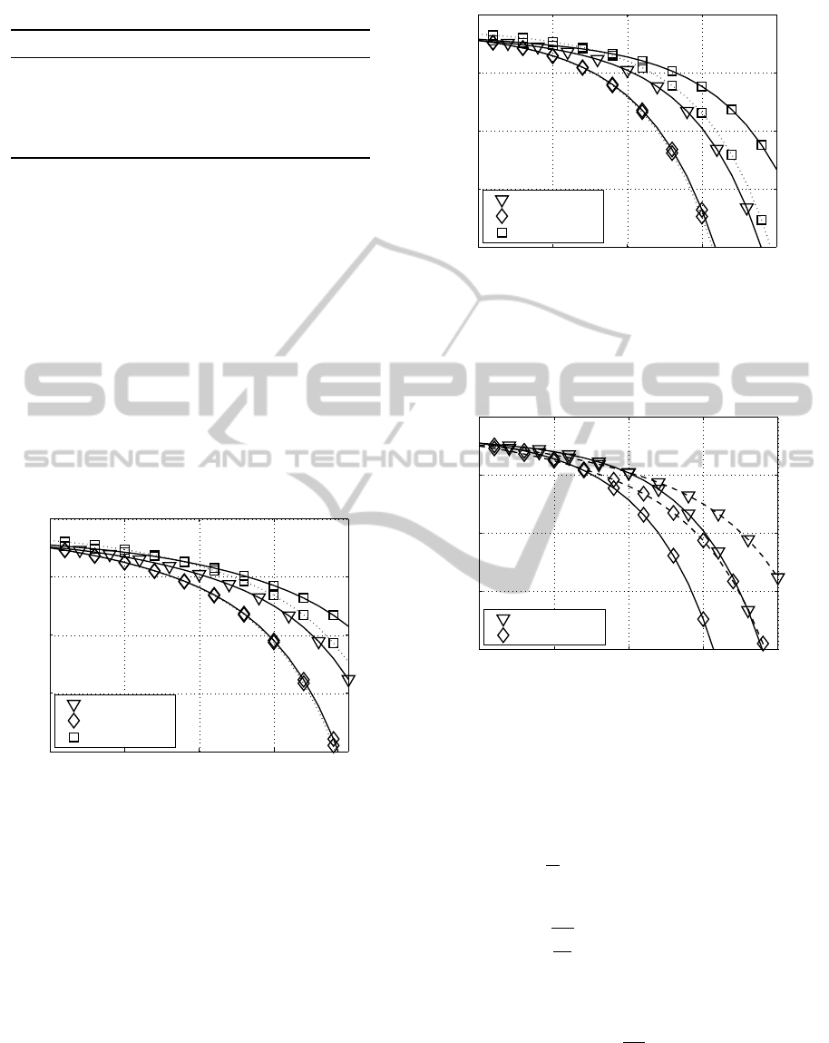
Table 1: Transmission modes.
throughput layer 1 layer 2 layer 3 layer 4
8 bit/s/Hz 256 0 0 0
8 bit/s/Hz 64 4 0 0
8 bit/s/Hz 16 16 0 0
8 bit/s/Hz 16 4 4 0
8 bit/s/Hz 4 4 4 4
The factor 4/5 is chosen so to guarantee that the
channel is not amplifying in any power allocation sit-
uation. In addition, the number of equalizer coeffi-
cients within the T-PMSVD model is chosen to be
10 and thus the factors by which the noise power is
weighted on each layer come out as θ
1
= 0.9768 and
θ
2
= 17.7729. Therefore, assuming equal QAM con-
stellations on all layers the modified noise power af-
fects the SNR of the second layer approximately 18
times more than the SNR of the first one. The calcu-
lated BER results as a function of the signal energy
to noise power spectral density E
s
/N
0
for both equal-
ization types are depicted separately in Fig. 7 and 8.
15 20 25 30 35
10
−8
10
−6
10
−4
10
−2
10
0
P
BER
→
10 ·log
10
(E
s
/N
0
) (in dB) →
(256,0) QAM
(64,4) QAM
(16,16) QAM
Figure 7: BER with PA (dotted line) and without PA (solid
Figure 7: BER with PA (dotted line) and without PA (solid
line) applying SVD-based equalization when transmitting
over the time-invariant (2×2) MIMO channel given by (31)
and (32) with 8 bit/s/Hz using the transmission modes intro-
duced in Table 1.
Here the (64,4) QAM transmission mode shows
the best results. Furthermore, comparing the SVD and
T-PMSVD results indicate that the quality ranking of
the transmission modes is similar for both equaliza-
tion types. Also, the benefits of using the equal SNR
power allocation method are visible. A direct compar-
ison between the SVD and T-PMSVD results is de-
picted in Fig. 9 and shows that the T-PMSVD quality
outperforms the SVD results.
The previous channel is now extended to a two-
path time-invariant (4 ×4) MIMO system with the
5 is chosen so to guarantee that the
channel is not amplifying in any power allocation sit-
uation. In addition, the number of equalizer coeffi-
cients within the T-PMSVD model is chosen to be
10 and thus the factors by which the noise power is
9768 and
15 20 25 30 35
10
−8
10
−6
10
−4
10
−2
10
0
P
BER
→
10 ·log
10
(E
s
/N
0
) (in dB) →
(256,0) QAM
(64,4) QAM
(16,16) QAM
Figure 8: BER with PA (dotted line) and without PA (solid
Figure 8: BER with PA (dotted line) and without PA (solid
line) applying T-PMSVD equalization when transmitting
over the time-invariant (2×2) MIMO channel given by (31)
and (32) with 8 bit/s/Hz using the transmission modes intro-
duced in Table 1.
lated BER results as a function of the signal energy
for both equal-
ization types are depicted separately in Fig. 7 and 8.
15 20 25 30 35
10
−8
10
−6
10
−4
10
−2
10
0
P
BER
→
10 ·log
10
(E
s
/N
0
) (in dB) →
(256,0) QAM
(64,4) QAM
Figure 9: BER comparison between the SVD-based (dashed
Figure 9: BER comparison between the SVD-based (dashed
line) and T-PMSVD-based equalization results (solid line)
when transmitting over the time-invariant (2 ×2) MIMO
channel given by (31) with 8 bit/s/Hz using the transmission
modes introduced in Table 1 and applying equal SNR PA.
polynomial channel matrix
H(z) = H
0
+ H
1
z
−1
(33)
with
H
0
=
8
15
1 0.6 0.5 0.3
0.5 0.8 0.6 0.4
0.4 0.5 0.7 0.5
0.3 0.4 0.5 0.6
(34)
and
H
1
=
H
0
2
. (35)
The corresponding BER results are shown in Fig.
10 and 11 for SVD as well as T-PMSVD process-
ing. The results show, that the (64,4,0,0) configura-
PECCS2015-5thInternationalConferenceonPervasiveandEmbeddedComputingandCommunicationSystems
322
15 20 25 30 35
10
−8
10
−6
10
−4
10
−2
10
0
P
BER
→
10 ·log
10
(E
s
/N
0
) (indB) →
(256,0,0,0) QAM
(64,4,0,0) QAM
(16,16,0,0) QAM
(16,4,4,0) QAM
(4,4,4,4) QAM
Figure 10: BER with PA (dotted line) and without PA (solid
Figure 10: BER with PA (dotted line) and without PA (solid
line) applying SVD-based equalization when transmitting
over the time-invariant (4×4) MIMO channel given by (33)
and (35) with 8 bit/s/Hz using the transmission modes intro-
duced in Table 1.
15 20 25 30 35
10
−8
10
−6
10
−4
10
−2
10
0
P
BER
→
10 ·log
10
(E
s
/N
0
) (in dB) →
(256,0,0,0) QAM
(64,4,0,0) QAM
(16,16,0,0) QAM
(16,4,4,0) QAM
(4,4,4,4) QAM
Figure 11: BER with PA (dotted line) and without PA (solid
Figure 11: BER with PA (dotted line) and without PA (solid
line) applying T-PMSVD equalization when transmitting
over the time-invariant (4×4) MIMO channel given by (33)
and (35) with 8 bit/s/Hz using the transmission modes intro-
duced in Table 1.
tion shows the best performance. Comparing these re-
sults with the (4,4,4,4) transmission mode, it turns out
that activating all MIMO layers results in a high BER,
based on activating layers with low quality. Directly
comparing both equalization types as shown in Fig.
12 highlights the superior BER performance of the
PMSVD-based equalization.
So far only time-invariant channels were stud-
ied. These investigations are now extended to time-
variant wireless channels. Here, a two path (4 ×4)
MIMO channel without a line-of-sight component is
analyzed (L
c
= 1), where the amplitudes are modeled
as Rayleigh distributed. The BER results are shown
in Fig. 13 and 14. Here the (16,16,0,0) QAM trans-
mission mode performs best for SVD as well as for
T-PMSVD equalization. Thus, not all layers have to
Figure 10: BER with PA (dotted line) and without PA (solid
15 20 25 30
10
−8
10
−6
10
−4
10
−2
10
0
P
BER
→
10 ·log
10
(E
s
/N
0
) (in dB) →
(64,4,0,0) QAM
(16,16,0,0) QAM
Figure 12: BER comparison between the SVD-based
Figure 12: BER comparison between the SVD-based
(dashed line) and T-PMSVD-based equalization results
(solid line) when transmitting over the time-invariant (4 ×
4) MIMO channel given by (33) with 8 bit/s/Hz using the
transmission modes introduced in Table 1 and applying
equal SNR PA.
Figure 11: BER with PA (dotted line) and without PA (solid
line) applying T-PMSVD equalization when transmitting
MIMO channel given by (33)
10 15 20 25
10
−8
10
−6
10
−4
10
−2
10
0
P
BER
→
10 ·log
10
(E
s
/N
0
) (in dB) →
(256,0,0,0) QAM
(64,4,0,0) QAM
(16,16,0,0) QAM
(16,4,4,0) QAM
(4,4,4,4) QAM
Figure 13: BER with PA (dotted line) and without PA (solid
Figure 13: BER with PA (dotted line) and without PA (solid
line) applying SVD-based equalization when transmitting
over a Rayleigh distributed (4×4) MIMO two path channel
with 8 bit/s/Hz using the transmission modes introduced in
Table 1.
be activated for achieving the best BER performance
results. The transmission mode performance for both
equalization types is also similar. Applying the easy
to implement equal SNR PA results in a significant
improvement of the BER. The direct BER perfor-
mance comparison depicted in Fig. 15 shows that the
T-PMSVD BER quality is superior to the SVD BER
quality.
7 CONCLUSION
In this paper broadband MIMO systems have been
described using polynomial matrix factorization. In
order to remove the MIMO channel interference
ResourceAllocationinSVD-assistedBroadbandMIMOSystemsUsing
PolynomialMatrixFactorization
323
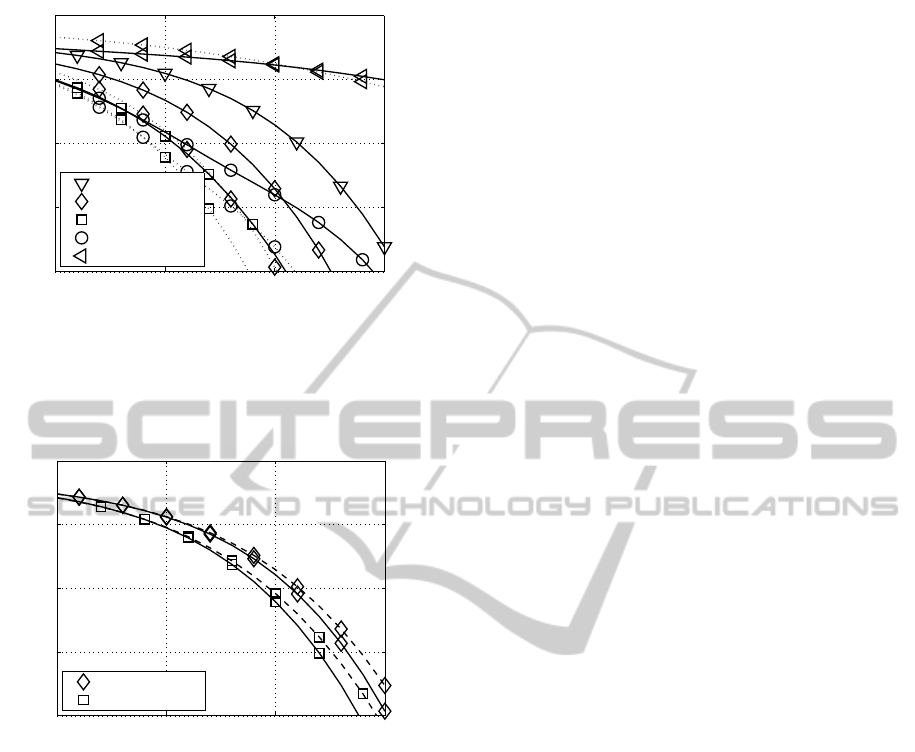
10 15 20 25
10
−8
10
−6
10
−4
10
−2
10
0
P
BER
→
10 ·log
10
(E
s
/N
0
) (in dB) →
(256,0,0,0) QAM
(64,4,0,0) QAM
(16,16,0,0) QAM
(16,4,4,0) QAM
(4,4,4,4) QAM
Figure 14: BER with PA (dotted line) and without PA (solid
Figure 14: BER with PA (dotted line) and without PA (solid
line) applying T-PMSVD equalization when transmitting
over a Rayleigh distributed (4×4) MIMO two path channel
with 8 bit/s/Hz using the transmission modes introduced in
Table 1.
5 10 15 20
10
−8
10
−6
10
−4
10
−2
10
0
P
BER
→
10 ·log
10
(E
s
/N
0
) (indB) →
(64,4,0,0) QAM
(16,16,0,0) QAM
Figure 15: BER comparison between the SVD-based
Figure 15: BER comparison between the SVD-based
(dashed line) and T-PMSVD-based equalization results
(solid line) when transmitting over a Rayleigh distributed
(4 ×4) MIMO two path channel with 8 bit/s/Hz using the
transmission modes introduced in Table 1 and applying
equal SNR PA.
a particular singular value decomposition algorithm
for polynomial matrices (PMSVD) including layer-
specific T-spaced equalization for eliminating the re-
maining inter symbol interference has been stud-
ied. This T-PMSVD technique has been compared
in terms of bit error rate performance with the well-
known spatio-temporal vector coding description ap-
plying SVD equalization. The simulation results
demonstrate that using T-PMSVD equalization the
BER performance is superior compared with applying
SVD. For both equalization types bit loading schemes
have been combined with equal SNR power alloca-
tion so as to optimize the BER performance. The
equal SNR criteria for power allocation seems to be
a good sub-optimum solution to improve the channel
performance. Furthermore, the bit and power loading
analogies between both equalization types have been
shown. The two different analyzed channels clarify
that the optimal QAM transmission mode largely de-
pends upon the used channel type and that the activa-
tion of all transmission layers doesn’t always lead to
the best performance.
REFERENCES
Ahrens, A. and Benavente-Peces, C. (2009). Modulation-
Mode and Power Assignment in Broadband MIMO
Systems. Facta Universitatis (Series Electronics and
Energetics), 22(3):313–327.
Ahrens, A. and Lange, C. (2008). Modulation-Mode and
Power Assignment in SVD-equalized MIMO Sys-
tems. Facta Universitatis (Series Electronics and En-
ergetics), 21(2):167–181.
Bingham, J. A. C. (2000). ADSL, VDSL, and Multicarrier
Modulation. Wiley, New York.
Foster, J., McWhirter, J., Davies, M., and Chambers, J.
(2010). An Algorithm for Calculating the QR and Sin-
gular Value Decompositions of Polynomial Matrices.
IEEE Transactions on Signal Processing, 58(3):1263–
1274.
Kühn, V. (2006). Wireless Communications over MIMO
Channels – Applications to CDMA and Multiple An-
tenna Systems. Wiley, Chichester.
McWhirter, J., Baxter, P., Cooper, T., Redif, S., and Fos-
ter, J. (2007). An EVD Algorithm for Para-Hermitian
Polynomial Matrices. IEEE Transactions on Signal
Processing, 55(5):2158–2169.
Proakis, J. G. (2000). Digital Communications. McGraw-
Hill, Boston.
Raleigh, G. G. and Cioffi, J. M. (1998). Spatio-Temporal
Coding for Wirless Communication. IEEE Transac-
tions on Communications, 46(3):357–366.
Raleigh, G. G. and Jones, V. K. (1999). Multivariate
Modulation and Coding for Wireless Communication.
IEEE Journal on Selected Areas in Communications,
17(5):851–866.
Sandmann, A., Ahrens, A., and Lochmann, S. (2014).
Modulation-Mode and Power Assignment in Optical
MIMO Systems using Polynomial Matrix Factoriza-
tion. In 10th International Conference on Mathemat-
ics in Signal Processing, Birmingham (United King-
dom).
Tse, D. and Viswanath, P. (2005). Fundamentals of Wireless
Communication. Cambridge, New York.
PECCS2015-5thInternationalConferenceonPervasiveandEmbeddedComputingandCommunicationSystems
324
