
Integrating Existing Proprietary System Models into a Model-driven Test
Process for an Industrial Automation Scenario
Kai Beckmann
Distributed Systems Lab, RheinMain University of Applied Sciences, Unter den Eichen 5, D-65195 Wiesbaden, Germany
Keywords:
MDSD, DSL, Metamodelling, Testing, MDT, Model-driven Testing.
Abstract:
The introduction of modern model-driven software development methodologies into the industrial practise
still proves to be a challenge. Especially small or medium-sized enterprises (SMEs) need an incremental
and continuous modernisation process, which incorporates existing projects, is customised and cost-effective.
Particularly, suitable solutions for model-based or -driven testing with test automation to increase the efficiency
are in demand. This paper presents an approach for integrating existing proprietary system models of an SME
partner for describing industrial automation processes into a model-driven test process, utilising a domain-
specific language for the test specification. The test objectives focuses on the correct implementation of
the communication and synchronisation of distributed state machines. The presented approach is integrated
into a test framework, which is based on the Eclipse Modelling Framework (EMF) and the Eclipse Test and
Performance Tools Platform Project (TPTP) framework. To separate the possibly changeable system and DSL-
specific models from the implementation of the test framework, a stable and more generic test meta model was
defined.
1 INTRODUCTION
While the model-driven aspect in software develop-
ment is considered state-of-the-art and part of the cur-
riculum of computer scientists/engineers, the compre-
hensive adoption in practise is still rare. This is es-
pecially true for small- or medium-sized enterprises
(SME) of the embedded and industrial automation
sector. Increasing software complexity necessitate
a modernisation of the development processes and
methodologies. Particularly the systematic testing is
a pressing concern creating the demand for proper so-
lutions.
Lack of time, missing knowledge, resistance
from parties involved, the need to integrate existing
projects and cost are reasons often heard why changes
in software development are so challenging. The in-
troduction of new processes, methodologies and tools
requires training time for developers to become pro-
ductive. Additionally, there is a social factor: devel-
opers have to relearn and accept new methodologies
as beneficial. SMEs are often captured in the day-
to-day business. There are seldom resources, such as
man-power or money available to restart from scratch.
For SMEs, these problems result in necessary re-
quirements for a successful modernisation of their
software development processes. The modernisation
process should be incremental and an introduction
should be possible in the day-to-day business. There
is a need to integrate and reuse existing projects, soft-
ware development artefacts and models. Domain-
specific adaptation to the existing development pro-
cesses and projects can help to lower the effort for
training and resistance offered of persons involved.
This paper presents an approach for integrating
existing proprietary system models into a new model-
driven test process facilitating a domain-specific lan-
guage for test case definitions. The test process is go-
ing to be embedded in the development process of an
existing project of a medium-sized company in the in-
dustrial automation sector. The existing system mod-
els are the result of an in-house development of the
company for modelling state machines and code gen-
eration for various platforms. The test objects com-
prise the communication and synchronisation of dis-
tributed state machines, since these aspects are not
part of the system model and implemented manually.
This work is part of an ongoing R&D project with the
company mentioned to develop a test framework for
automated and model-driven tests.
In chapter 2 the necessary information about the
properties of the system model and technologies em-
255
Beckmann K..
Integrating Existing Proprietary System Models into a Model-driven Test Process for an Industrial Automation Scenario.
DOI: 10.5220/0005240302550262
In Proceedings of the 3rd International Conference on Model-Driven Engineering and Software Development (MODELSWARD-2015), pages 255-262
ISBN: 978-989-758-083-3
Copyright
c
2015 SCITEPRESS (Science and Technology Publications, Lda.)
ployed is given. Chapter 3 starts with a brief outline of
our solution and the overall architecture and presents
the concept of the approach. The implementation is
outlined in chapter 4, chapter 5 describes experience
gained so far. Related work is discussed in section
6, and in section 7 a summary and an outlook upon
future work are given.
2 BACKGROUND
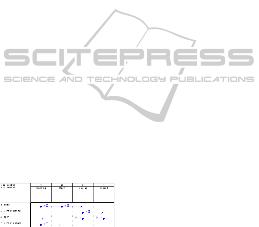
2.1 Sequential Function Tables
Sequential Function Tables (SFT) are a proprietary
table-based notation for state machines developed by
Eckelmann AG (Wiesbaden, Germany) (Eckelmann
AG, 2014). An example for a simple door control is
given in Figure 1. States are noted in the columns
and events in the rows. A transition is represented by
an arrow from the start to the end state in the row of
the triggering event. Transitions of the same event are
merged in one arrow. In the example of Figure 1 the
event close, representing the request to close the door,
can trigger a state change from Opening and Open to
the state Closing. Both arrows are merged pointing to
the target state.
Furthermore, transitions can have a priority, which
represents the order of evaluation of events during
run-time. States can be ordered hierarchically into
state groups. Transitions, and the entering or leav-
ing of states or state groups, can cause actions, ex-
ecuted at run-time. The advantage of this notation is
readability for its state machines with many states and
transitions. As an example, state machines with more
than 55 states and 45 events developed in practise are
still manageable.
Figure 1: Example for SFT notation.
SFT system models are defined with the in-house
tool StateCase, which generates code for various lan-
guages like C, C#, Java or even VHDL for FPGA tar-
gets. The code generation covers the structure and
transitions of the state machines and code stubs for
action and event processing which have to be imple-
mented manually. The communication and synchro-
nisation of distributed state machines is not part of the
modelling and code generation process. Additionally,
SFTs define state machine “classes” whose instances
are deployed manually as well.
2.2 Eclipse Modeling Framework
The Eclipse Modeling Framework (EMF) provides
the modelling and code generation facilities for the
model-based or -driven development of tools and
projects with Eclipse (EMF, 2014). Furthermore,
EMF is the core of other Eclipse-based tools and uses
the meta-meta-model Ecore as common model basis.
The EMF project provides an implementation of the
OMG “Query View Transformation” (QVT) standard
for specifying model to model (M2M) transforma-
tions for Ecore-based models (Eclipse QVT, 2014).
The Xtext framework supports the development
of domain specific languages (DSL) for model-driven
software-development processes (MDSD) within
Eclipse and uses EMF as core (Xtext, 2014). By im-
porting other Ecore-based meta models into the gram-
mar, other models can be integrated and referenced.
The Eclipse Test & Performance Tools Platform
Project (TPTP) (TPTP, 2014) was initiated by IBM
in 2002 as the “Hyades” project and provides Eclipse
plugins to develop and execute unit and performance
tests for applications with Eclipse. The main use case
is the test of Java applications, but the framework
provides extension points to adapt it to other envi-
ronments and domains. Currently, the project is not
actively being developed and is preserved in the last
stable version.
2.3 Test Modelling Standards
TestIF is the Test Information Interchange Format, a
currently finalised standard of the OMG for the “ex-
change of test information among tools, applications,
and systems that utilize it” (OMG, 2014). The stan-
dard defines a platform-independent meta model. To
exchange test information, the purpose and the struc-
ture of tests can be defined, as well as the test data and
expected responses of the system under test (SUT).
Furthermore, the results and artefacts of the execution
of tests can be specified as well.
The UML testing profile (UTP) is a UML profile
to extend UML with semantic elements for test mod-
elling (Baker et al., 2008). UTP provides the seman-
tics to model test architecture, behaviour, data and re-
sults using UML. Other UML profiles can be incor-
porated as well, so it is possible to associate require-
ments from SysML with UTP test objectives. Besides
the profile, the UTP standard defines a MOF-based
meta model as well.
MODELSWARD2015-3rdInternationalConferenceonModel-DrivenEngineeringandSoftwareDevelopment
256
3 CONCEPT
3.1 Use Case & Requirements
In this use case the automated and model driven test-
ing is introduced in a project at the end of its ac-
tive development cycle. The SUT consists of several
distributed state machines running on heterogeneous
platforms, like control systems, micro-controllers and
FPGAs. The overall application must satisfy real-
time and safety constraints. SFTs are used to specify
the structure of the state machines.
In the original state of the project, a commercial
tool is used for the acquisition and management of ap-
plication requirements and related test cases. A vari-
ety of mock-ups and simulators have been developed
for manually executed integration and system tests.
The manual tests consist of sequences of consecutive
test steps. Test steps can either drive the test by oper-
ating the simulators and mock-up components, or in-
struct the tester to validate the correct SUT behaviour.
The interaction of all test components is complex and
the manual test execution is very time consuming.
Therefore, regular and complete regression tests are
not feasible in practise.
Through discussions with our industrial partner
the following main requirements were identified:
• Need for a test DSL, adjusted to the existing man-
ual test specification and structure
• Reuse of the existing system models for test spec-
ification
• Model-driven process with the usage of estab-
lished software standards
• Integration in a test framework for test specifi-
cation, management, execution and result evalu-
ation/reporting
• Reusability of the approach and generic imple-
mentation for other projects and industrial users
• Usage of Open-Source tools
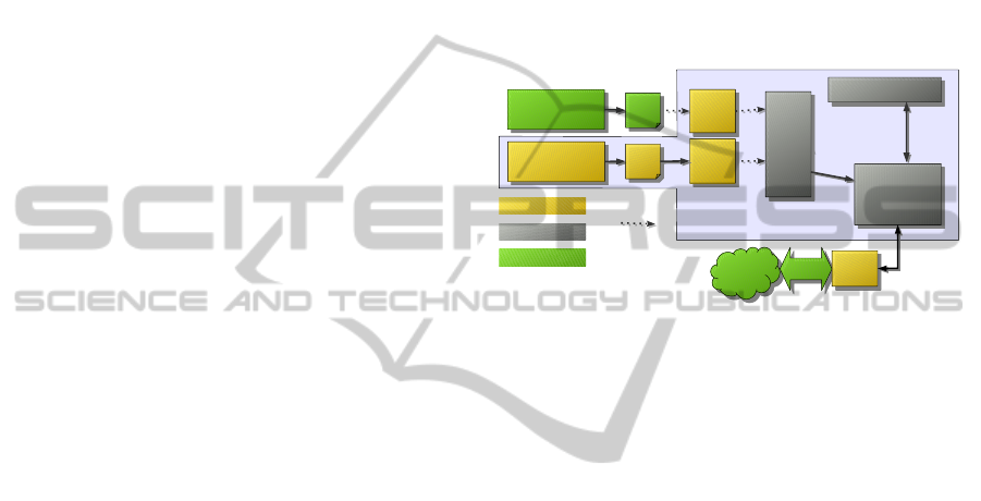
3.2 Approach
To meet the requirements identified with our indus-
trial partner, an approach based on a model-driven
test process within a test framework was developed,
whose overall architecture is depicted in Figure 2.
The existing SFT-based system models are imported
and reused in the test specification, for which a DSL
for distributed state machines was developed.
One requirement for this approach is that it should
be reusable for other (at least related) use cases and
projects. Therefore, the meta models of the DSL and
proprietary system model are not directly employed
in the test process, since they are too platform and use
case specific. Instead, an overall meta model, named
TEFAModels, was developed, which merges system
and test model aspects. Model transformations con-
vert the DSL models and proprietary system models
to a TEFAModels representation, thereby decouple
them from the test framework. This also allows to
replace the currently textual DSL with other possi-
ble notations, like a graphical version. Changes of
the system model are limited to the transformation as
well, if an adaptation of TEFAModels is not required.
Eclipse
View Testing (TPTP)
View Testing (TPTP)
StateCase tool
StateCase tool
Generic
model
Generic
model
DSL
specific
model
DSL
specific
model
TPTP
Test execution
TPTP
Test execution
Test specification
(DSL)
Eclipse-Editor
Test specification
(DSL)
Eclipse-Editor
domain-specific
generic/reusable
QVT transformation
Test
case
Test
case
XML
XML
SUT
SUT
WCF-GW
WCF-GW
TPTP
Agent
TPTP
Agent
existing parts
Tool
specific
model
Tool
specific
model
Figure 2: Overall architecture of the test framework.
In TEFAModels, tool and platform specific model
elements are separated from platform independent as-
pects, which simplifies extensions and adaptations.
The structure and the scope is oriented on other
established software and test standards. However,
TEFAModels is not intended to be a completely
generic test meta model for any possible use case or
software application. Reasonable reusability is lim-
ited to comparable scenarios with distributed state
machines and a sequential test step execution. Nev-
ertheless, these constrains still allow a wide applica-
bility in the industrial automation sector.
The Eclipse Test and Performance Tools Platform
(TPTP) serves as a foundation for test management
and execution and was adapted to the developed meta
model. The Eclipse Modeling Framework (EMF) pro-
vides the facilities for the model-driven process. The
test interface to the SUT is realised by a gateway de-
veloped by the industrial partner (WCF-GW in Figure
2). Active state machine instances can be queried and
events of state transitions subscribed. This interface is
operated by a TPTP agent, which relays information
and commands between the SUT and the test frame-
work.
3.3 Integration of the Proprietary
System Model
In the presented approach the proprietary system
model is decoupled from the meta model used in
IntegratingExistingProprietarySystemModelsintoaModel-drivenTestProcessforanIndustrialAutomationScenario
257
the test execution. Therefore, the proprietary system
model has to be imported or parsed into a processable
representation and then transformed to a more generic
model as part of the model-driven test process. In
such a system meta model, all information relevant
to the test of the proprietary system model has to be
representable.
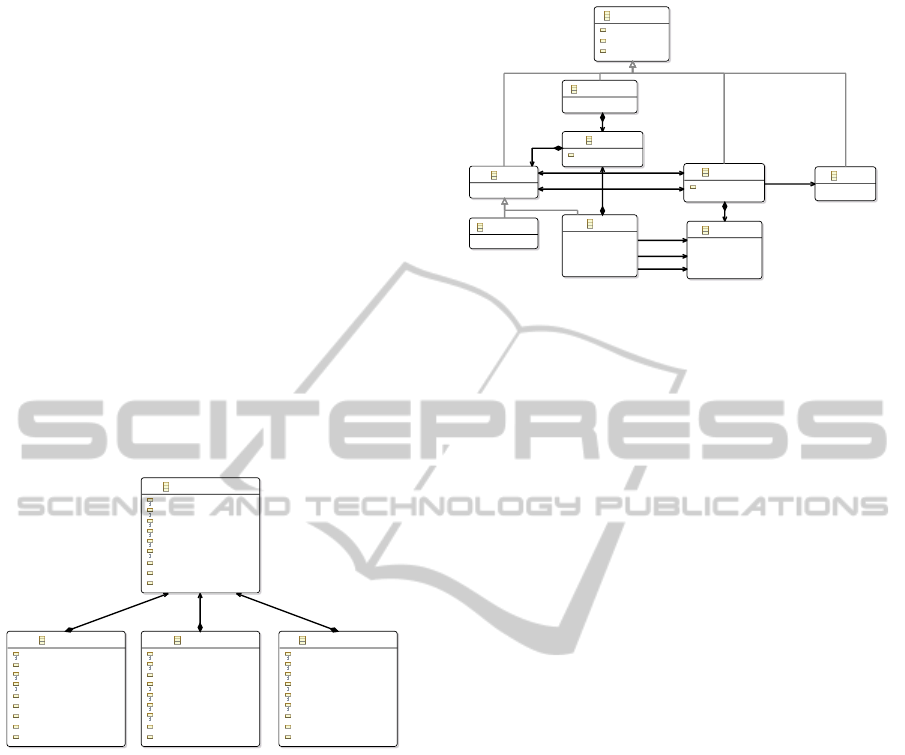
The reason to use an approach with an interme-
diate model transformation step can be illustrated by
the use case presented in this paper: in this use case,
the state machines of the system are modeled with
the tool StateCase and stored in a proprietary XML
format. An XML schema can be mapped to a corre-
sponding meta model. Figure 3 shows a fragment of
the resulting meta model structure for the StateCase
format, using the EMF facilities for this task. The
internal StateCase-specific structure, looped through
the XML format, becomes evident; IDs are used to
reference elements like states, events or transitions.
Inheritance is not used.
SFTOBJECTType
iD : String
nAME : String
iDENTIFIER : String
iDENTMOD : String
tITLE : String
cOMMENT : String
cLASS : String
subversion : String = 0
version : String = 1
TRANSITIONType
sTATEIDSOURCE : String
sTATEIDTARGET : String
eVENTID : String
pRIORITY : String
tYPE : String
uMLTYPE : String
sELSZENARIO : String
subversion : String = 0
version : String = 1
EVENTType
rOWINDEX : String
cONDITIONID : String
hEIGHT : String
wIDTH : String
nEGATIONOF : String
hASNEGATION : String
cAT : String
subversion : String = 0
version : String = 1
STATEType
cOLINDEX : String
iNITIAL : String
rETURNSTATE : String
tEMPORARY : String
gROUPID : String
hEIGHT : String
wIDTH : String
subversion : String = 0
version : String = 1
[1..1] sFTOBJECT
[1..1] sFTOBJECT
[1..1] sFTOBJECT
Figure 3: Generated meta model for SFT.
The usage of a model structure like this would
complicate the further model-driven test process.
Only the effort to resolve references during runtime
can justify a transformation into a more applicable
model. Here, the meta model TEFAModels was de-
veloped to provide a more generic model for dis-
tributed state machines. The structure, displayed in
Figure 4, is derived from a simplified version of the
UML model for state machines (OMG, 2011), since
it is well established and meets the requirements.
From this platform-independent meta model of
state machines, SFT-specific elements are derived, en-
riched with the information of the SFT-models not
generically representable and necessary for the test
specification and execution. Thereby, a PIM and PSM
layer are established.
NamedEntity
name : EString
id : EString
desc : EString
StateMachine
Region
priority : EInt = 0
Node
Pseudostate
State
Transition
priority : EInt = 0
Behaviour
Event
[0..*] region
[0..*] state
[0..*] region
[1..1] source
[0..*] outgoing
[1..1] target
[0..*] incoming
[0..1] entry
[0..1] do
[0..1] exit
[0..1] effect
[1..1] trigger
Figure 4: Generic meta model for state machines, derived
from UML.
3.4 Domain-specific Test Modelling
Language
A DSL should be specific for the given use case. In
the approach presented in this paper the existing sys-
tem model is reused for the test specification with the
DSL, for example to define a predicate over the order
of occurring transitions of state machines specified in
the system model.
In this use case a DSL with a textual C-like syntax
was developed, because the testers of the cooperation
partner are developers familiar with a representation
like this. In other use cases or with different domain
experts this might not be favored. Though, with the
decoupling of the DSL meta model from the more
generic TEFAModels representation, it is possible to
provide different DSLs, specific for the given needs,
unified in the transformation process.
In the following part of this section the character-
istics of the developed test DSL for our project part-
ner are presented. The test objective is the valida-
tion of the manual implementation of the generated
state machine stubs, in which the communication and
synchronisation between distributed state machines is
realised. The chosen structure reflects the require-
ments of the project partner, the capabilities of the test
system and especially the sequential execution of the
tests.
Tests are organised in test suites which contain a
set of consecutive test cases. A test case itself consists
of a sequence of test steps and should have pre- and
post-conditions. These specify the state the SUT has
to have before and after a test case is executed. In
addition, conditions can be defined for test steps as
well. If a pre-condition is not met, the test case is
aborted and the next coequal step in the sequence is
executed. It is possible to define alternative sequences
to remedy previous abortions.
MODELSWARD2015-3rdInternationalConferenceonModel-DrivenEngineeringandSoftwareDevelopment
258
A single test step can either interact with the SUT
to drive or control the test execution or validate the
SUT behaviour. A test is driven by forcing events to
trigger transitions of state machines. With this mech-
anism, a SUT can be pushed into any reachable state.
Occurring transitions are monitored and used for the
behaviour validation of the SUT.
The expected SUT behaviour is modeled using
predicates over permitted paths of state transitions.
These paths can span multiple state machine instances
including distributed configurations to reflect their
interaction with each other, which we call “global
paths”.
A s s e r t {
P a t h A s s e r t {
sm1 : s t a t e 1 −> sm2 : s t a t e a −> ∗
−> ( sm1 : s t a t e 2 or sm1 : s t a t e 3 )
} t i m e o u t 300
P a t h A s s e r t {
n o t sm1 : s t a t e 4
}
}
Listing 1: Example for behaviour specification.
A small example of a behaviour definition with
two state machine instances sm1 and sm2 is given in
Listing 1. A global path is defined from the state 1 of
the sm1 to the state a of sm2. As next step in the path,
a wildcard specifies that any transition of any state
machine instance is acceptable if as next step the path
ends in the state
2 or the state state 3 of sm1. This
behaviour has to be observed within 300 ms, other-
wise the test fails. In parallel, the second PathAssert
shall be evaluated during test execution, in which the
occurrence of a transition to the state state 4 of sm1
would lead to a failure of the test.
The modeling elements of the example can be
joined as needed; the timeout can be specified option-
ally. For the given use case and the current develop-
ment state, these expressions are sufficient. An exten-
sion regarding more detailed real-time constraints is
under construction.
As a constraint of the test execution environment
the given test harness interface to the SUT does not al-
low access to internal variables of the SUT. Therefore,
the expressiveness of the test specification is limited
to states and transitions of the state machines. Since
the system model does not contain information about
the state machine instances and their deployment, this
information has to be specified as a prefix of the test
specification.
3.5 Generic Test Meta Model
The purpose of the developed meta model TEFAMod-
els is to provide a stable model foundation for the test
framework. Besides the state machine based system
model from section 3.3 and the test information de-
fined by the DSL, it contains necessary aspects of test
management, test structure, execution artefacts and
test results. This meta model was not defined from
scratch, but uses concepts of existing and related stan-
dard models. Thereby it can profit from the experi-
ence of other projects and might ease a future trans-
formation into these established representations. The
main sources are TestIF, UTP and the internal meta
model of TPTP.
The basic structure of the tests in the meta model
in the form of sequences of test cases, test steps and
test sets is adopted from TestIF. Regarding test re-
sults, the UTP verdict definition is used, extended by
the more detailed logging and justification elements
of the TPTP meta model.
The reason not to use the meta model of TPTP
as primary foundation is the tight coupling of the
meta model to the testing of object-oriented applica-
tion software. Furthermore, the information needed
for the validation of a test case is not part of the meta
model, but encapsulated by domain- and platform-
specific implementations. An adaptation to the given
use case was not considered reasonable. As a draw-
back of this decision, parts of the TPTP test execution
implementation had to be reimplemented.
TestCase
Sequence
TestStepTestStepTestStep
Sequence
TestCond
TestDriver
Behaviour
Init-Seq. Start Test
TestDriver
Init-Seq.
Validation
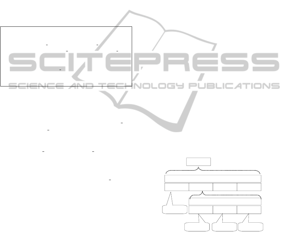
Figure 5: Example for a test case structure.
The test structure of the TEFAModel is similar to
TestIF, with the exception that a test suite represents
a single encapsulated test model instance. A Test-
Suite contains the test cases with expected behaviour,
the deployment and configuration on the SUT and the
results and traces of executed tests. There are two
kinds of test objects: sequence objects and atomic en-
tities. Sequence objects like TestCase, TestStep and
TestDriver can contain a list of other test objects,
whereas atomic entities as TestDriverStep, TestCon-
IntegratingExistingProprietarySystemModelsintoaModel-drivenTestProcessforanIndustrialAutomationScenario
259

dition and BehaviourDefinition can only be enclosed
by a sequence object. The test objects can be com-
bined in any order as needed, but a basic structure,
as exemplary displayed in Figure 5, is needed for
the test execution. A TestCase should contain a se-
quence of TestDriver and TestStep objects. These ob-
jects can contain other sequences or TestDriverStep
and BehaviourDefinition objects. The latter models
atomic interaction with the SUT or assertions for the
behaviour validation. As described in section 3.4, the
execution of the test traverses the sequence and eval-
uates the elements. For this example, the SUT is ini-
tialised with one driver sequence and another one trig-
gers the start of a validation step.
Given the restrictions of the use case towards the
test interface to the SUT, the SFT-specific derivations
of TestDriverStep are limited to force events of state
machines. To control the test execution, TestCondi-
tion derivations can be inserted in the sequence halt-
ing the process until certain conditions are met, e.g.,
a state machine has entered a defined state.
The expected SUT behaviour is not specified in
detail in TEFAModels, since the validation during the
test execution is performed by generated code. There-
fore, the SFT-specific derivation of the Behaviour-
Definition contains the path to the generated Java file
only, which has to be instantiated during run-time.
The execution of a test is represented by a TestRun
object. Each test run references the test object used,
results and time of execution. The monitored be-
haviour of a SUT is represented in a trace of state
transition events. These events reference the corre-
sponding state machine elements of the system model
and contain the required information about their oc-
currence, such as time-stamps, sequence numbers etc.
A trace event is assigned to the active test runs. A test
result contains the common verdict information if a
test has passed, failed or is inconclusive. Addition-
ally, a VerdictReason similar to the TPTP meta model
can specify the reason in more detail.
4 REALISATION
For the prototypical realisation of the test framework,
several plugins for Eclipse and TPTP have been de-
veloped to integrate StateCase, the new test modelling
environment and the test execution. The integration
of the StateCase XML files uses the EMF facilities,
and all meta models are based on Ecore. The DSL is
specified and the tool support realised using the Xtext
framework. All model transformations are described
and conducted by the QVT Operational implementa-
tion of Eclipse. To be able to use the Kepler (4.3) ver-
sion of Eclipse and meta modeling tooling support,
the necessary TPTP plugins were ported from the He-
lios version of Eclipse, which is presented in a paper
for a sibling project (Thoss et al., 2014).
Based on the DSL grammar, the Xtext framework
generates a corresponding meta model, a parser and a
comfortable editor for Eclipse. For integrating the ex-
isting system models, the grammar has to import the
system meta model discussed in section 3.3, and it has
to reference the state machine elements. An Xtext re-
source service provider has been implemented to pro-
vide access to the system models for the generated
Eclipse editor. As a result, the test models directly ref-
erence elements of the imported system models. Fur-
thermore, the editor provides appropriate suggestions
and autocompletion during test specification.
The test structure and deployment information of
the DSL are transformed to a TEFAModel instance
which can be processed by the test framework for test
execution. This transformation, realised with QVT,
uses the DSL meta model as source and has to be
adapted if the DSL changes in the future.
The expected SUT behaviour is not modeled in
TEFAModels yet and therefore not transformed. In-
stead, the Eclipse Xtend language is used to generate
the Java code for non-deterministic finite automata
(NFA), representing the specified assertions or pre-
dicts. The NFA is part of the test oracle and dynami-
cally instantiated during the test execution. The NFA
consist of all possible valid state graphs the predicts
or assertions allow for a validation step. During test
execution, the test framework monitors the SUT state
transitions and relays these events to the test oracle,
which drives the contained NFA. If an NFA enters a
valid final state, the test passes. On the other hand, a
test fails if reaching a final state becomes impossible
or a timeout occurs.
5 EVALUATION AND LESSONS
LEARNED
As part of an iterative development process, several
versions of the test framework have been evaluated
by domain experts of our industrial partner. The feed-
back led to changes of the requirements and necessary
feature sets. Focus in the first iterations was on usabil-
ity and expressiveness of the test specification and the
test process. The version considered in this chapter
comprises the whole model-driven test specification
process and the connection to the SUT’s test interface,
integrated in Eclipse and TPTP. The detailed report-
ing of the test results is planned until end of 2014.
The (re-) modelling of the existing manual test us-
MODELSWARD2015-3rdInternationalConferenceonModel-DrivenEngineeringandSoftwareDevelopment
260

ing the DSL and the facilities of the test framework
turned out to be difficult at the beginning. To con-
duct a manual test, the tester interacts with several
test components and external applications. The in-
tegration or control of these components was not con-
sidered at first, since the heterogeneous interfaces re-
quired significant effort to automate them. As a con-
sequence, options to call shell scripts and to inter-
act with the tester during test execution were added
as requirements. Furthermore, the expressiveness of
the test DSL and the automated test execution allows
a much finer-grained control over tests, which the
testers were unaccustomed to. As a result, the de-
veloped test cases were relatively simple initially, but
with increasing familiarity the testers approved of the
new potential.
The introduction of automated test execution
showed the typical improvements of reduced execu-
tion time and deterministic test repetition in compari-
son to the previous manual test execution.
The integration of the existing system model and
its reuse for test specification is positively appreciated
by the domain experts. It supports the development of
tests and reduces errors and mistakes. Especially the
tooling integration with autocompletion and sugges-
tions based on the imported system model is reckoned
as beneficial.
TPTP had to be adapted and customised more than
expected, mostly because of the TPTP meta model.
As motivated in section 3.5, an adaptation of the meta
model was not consisted reasonable. Therefore, the
integration of our TEFAModels required significant
implementation efforts. The parts of TPTP which ref-
erences the TPTP meta model in the source code had
to be adapted or reimplemented. Most effort went
into test execution, since our approach differs not only
by the meta model, but also in the basic test struc-
ture. On the other hand, this also permits a much
deeper control of the online test execution and vali-
dation, specifically for the test of distributed state ma-
chines, than the given TPTP implementation. In gen-
eral, the chosen framework architecture and the sep-
aration of meta models in the model-driven approach
proved to be beneficial. The test framework can be
adjusted to changes and additions easily. Four new
StateCase versions were introduced during the devel-
opment. Adaptations were limited to the regenera-
tion of the XML-to-Ecore mapping and to modifying
small parts of the QVT transformation. Even if new
attributes or information are introduced, the separa-
tion of platform-independent from platform-specific
models in TEFAModels limits the required changes.
6 RELATED WORK
Domain-specific languages, having been an estab-
lished methodology for a long time, became quite
popular recently. The main advantage of DSLs are
the “improving [of] productivity for developers and
improving [of] communication with domain experts”
(Fowler, 2010). As part of the model-driven software
development, DSLs simplify the specification of for-
mal models and the usage for domain experts (Stahl
et al., 2006). Therefore, there are several successful
applications of DSLs for test specification purposes
in literature and practise. Several model-based test-
ing tools are using some flavor of domain-specific
language or model for the test model specification
(Shafique and Labiche, 2010; Mussa et al., 2009).
The selection of a proper testing language and test
approach depends on the use case, the test organisa-
tion and the SUT. In (Hartman et al., 2007) this prob-
lem area is surveyed, and the authors provide guide-
lines to support the decision depending on the specific
environment. It is pointed out that DSLs have many
advantages, but the implementation causes significant
effort and needs specialised development knowledge,
especially for in-house solutions. It is stated that the
usage of open source projects lowers the effort and
reduces the dependency on third-party vendors.
In (Wahler et al., 2012) an approach similar to
ours is presented. The use case is the development
of an automated testing system for “a software li-
brary for an embedded real-time controller used in
automating processes”. Existing manual tests which
take over a person month to execute, were remod-
eled with a DSL and automatically executed. In con-
trast to our use case, the test system can access in-
ternal variables, events and alarms of the SUT by an
OPC-server, whereas our test interface is limited to
the monitoring of transitions of state machines.
Furthermore, the existing variables and possible
events of the SUT are queried from the OPC-server
and made available in the test specification editor. In
our approach the existing proprietary system model is
integrated and therefore, the test specification phase
is independent from the access to the SUT. Neverthe-
less, the utilisation of an OPC-server and the possi-
bility to access process variables allows more com-
prehensive predicates over the SUT behaviour. Since
the usage of OPC is common in the automation con-
text, the authors’ realisation can certainly be applied
to other use cases. Another similarity is the usage of
Eclipse and the Xtext framework for the realisation.
However, the authors implemented the test framework
from scratch and the test execution is realised with
Scala using the AST representation of the test model.
IntegratingExistingProprietarySystemModelsintoaModel-drivenTestProcessforanIndustrialAutomationScenario
261

In our approach, we reused and adapted the TPTP
framework and we use stable Ecore-based models for
the test specification and execution process. Changes
in the DSL have to be respected in a model transfor-
mation and do not necessitate adaptation in the test
execution implementation.
7 SUMMARY, FUTURE WORK
The paper presented an approach for integrating ex-
isting proprietary system models into a new model-
driven testing process. For an industrial automa-
tion scenario, a domain-specific language was devel-
oped to specify test cases for a SUT consisting of
distributed state machines. As part of the model-
driven test process, a meta model consisting of a more
generic representation of the system model and nec-
essary testing aspects was defined. The existing sys-
tem model and the DSL are integrated in the test-
ing process by model transformations which decouple
the domains, keeping changes and adaptations locally.
The realisation is based on Eclipse and the Eclipse
modelling framework. As a foundation for the test
framework, the TPTP project was adapted and cus-
tomised to the use case. The iterative development
with continuous evaluation of intermediate results by
domain experts ensured the practical usability and ac-
ceptance by the testers.
The version of the test framework presented in this
paper lacks the complete reporting and evaluation ca-
pabilities of test results, which is ongoing work. Fur-
thermore, the DSL and test evaluation is currently ex-
tended with real-time capabilities to enhance the us-
ability of the test framework further.
So far, the defined test meta model has generic
parts, but is limited to a use case based on state ma-
chines. Thus, it is a specialised solution. As a next
step, the TEFAModels will be used as an intermediate
model for a transformation into a UML/UTP based
representation. Besides the possibility to exchange
and reuse these models, adapting the test framework
to execute and manage tests represented using these
standards will result in broader applicability.
ACKNOWLEDGEMENTS
The master students Matthias Jurisch and Michael Po-
etz, my colleague Marcus Thoss and Horst Wiche and
Matthias Englert from the Eckelmann AG contributed
to the presented work. Furthermore, I want to thank
my Ph.D. supervisors Prof. Dr. Kroeger from Rhein-
Main University of Applied Sciences and Prof. Dr.
Brinkschulte from Goethe University Frankfurt am
Main.
This project (HA project no. 317/12-07) is
funded in the framework of Hessen ModellProjekte,
financed with funds of LOEWE – Landes-Offensive
zur Entwicklung Wissenschaftlich-Oekonomischer
Exzellenz, Foerderlinie 3: KMU-Verbundvorhaben
(State Campaign for the Development of Scientific
and Economic Excellence).
REFERENCES
Baker, P., Dai, Z. R., Grabowski, J., Haugen, O. y., Schiefer-
decker, I., and Williams, C. (2008). Model-Driven
Testing: Using the UML Testing Profile. Springer.
Eckelmann AG (2014). http://www.eckelmann.de/en.
Eclipse QVT (2014). Eclipse Model to Model Transforma-
tion Project. www.eclipse.org/mmt/qvto/.
EMF (2014). Eclipse Modeling Framework Project (EMF).
http://www.eclipse.org/modeling/emf/.
Fowler, M. (2010). Domain-Specific Languages, volume
5658. Pearson Education.
Hartman, A., Katara, M., and Olvovsky, S. (2007). Choos-
ing a Test Modeling Language: a Survey. In Hard-
ware and Software, Verification and Testing, volume
4383 of LNCS, pages 204–218. Springer.
Mussa, M., Ouchani, S., Sammane, W. A., and Hamou-
Lhadj, A. (2009). A Survey of Model-Driven Testing
Techniques. In 9th International Conference on Qual-
ity Software, QSIC ’09., pages 167–172, Jeju, Korea
(South). IEEE.
OMG (2011). OMG Unified Modeling Language (OMG
UML), Superstructure.
OMG (2014). Test Information Interchange Format 1.0 -
Beta 2. http://www.omg.org/spec/TestIF/1.0/Beta2/.
Shafique, M. and Labiche, Y. (2010). A Systematic Review
of Model Based Testing Tool Support. Technical re-
port SCE-10-04, Carleton University.
Stahl, T., Voelter, M., and Czarnecki, K. (2006). Model-
Driven Software Development: Technology, Engineer-
ing, Management. John Wiley & Sons.
Thoss, M., Beckmann, K., Kroeger, R., Muenchhof, M.,
and Mellert, C. (2014). A Framework-based Ap-
proach for Automated Testing of CNC Firmware.
In Proceedings of the 2014 Workshop on Joining
AcadeMiA and Industry Contributions to Test Au-
tomation and Model-Based Testing, JAMAICA 2014,
pages 7–12, New York, NY, USA. ACM.
TPTP (2014). Eclipse Test & Performance Tools Platform
Project. http://eclipse.org/tptp/index.php.
Wahler, M., Ferranti, E., and Steiger, R. (2012). CAST:
Automating Software Tests for Embedded Systems. In
Software Testing, Verification and Validation (ICST),
2012 IEEE Fifth International Conference on, pages
457 – 466.
Xtext (2014). Eclipse Xtext Project. http://
www.eclipse.org/Xtext/.
MODELSWARD2015-3rdInternationalConferenceonModel-DrivenEngineeringandSoftwareDevelopment
262
