Visual Feedback System for Intuitive Comprehension of Self-movement
and Sensor Data for Effective Motor Learning
Dan Mikami
1
, Ayumi Matsumoto
1
, Toshitaka Kimura
2
, Shiro Ozawa
1
and Akira Kojima
1
1
Media Intelligence Laboratories, NTT, 1-1 Hikarino-Oka, Yokosuka, Kanagawa, Japan
2
Communication Science Laboratories, NTT, 3-1 Morinosato-Wakamiya, Atsugi, Kanagawa, Japan
1 OBJECTIVES
Information feedback systems for motor learning
have been widely studied. Means of providing feed-
back can be divided into two approaches: auditory
and visual. Audio information can provide feedback
without preventing training motions a trainee makes
when moving (Effenberg et al., 2011). However, due
to the intrinsic feature of sound, i.e., that is one-
dimensional temporal data, the information it can ex-
press is quite limited.
Visual feedback has also been widely studied
(Guadagnoli et al., 2002; Wieringen et al., 1989).
Feedback of this type can provide a great deal of in-
formation through the use of visual information. For
example, Chua et al. have developed a training sys-
tem in a VR environment (Chua et al., 2003). The
system uses a motion capturing technique to capture
a trainee’s movements and shows the corresponding
trainer’s movements. Choi et al., have proposed a
system that estimates motion proficiency on the ba-
sis of motion capture data (Choi et al., 2008). How-
ever, though visual information may enhance motor
learning efficacy, there are two problems that make it
difficult for most existing visual feedback systems to
be used in practice.
One problem is in setting. The aforementioned
systems employ motion capture techniques to obtain
human movement. The overhead for setting mocap
systems and training site restrictions deteriorate the
systems’ efficacy. The other problem is in the tim-
ing of visual feedbacks. The simplest visual feedback
system is training in front of a mirror. In this case,
the trainee has to get visual feedback while he or she
is moving, which disrupts practice. Another simple
visual feedback system is capturing and watching a
video. In this case, the temporal gap between captur-
ing and watching gets longer, and this degrades feed-
back efficacy.
In recent years, small sensors have been developed
that enable information of various types such as sur-
face electromyography (EMG), cardiac rate, and res-
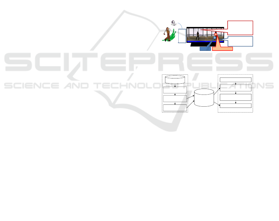
PC
Trainee's motion
with delay
Reference motion
in synchronization
with current motion
EMG Cardiac rate
Figure 1: Typical use case of the proposed system.
Reference
movement storage
1-1) Reference
movement loading
1-2) Synchronization
motion setting
2-2) Motion feature extraction
& template matching
2-3) Synchronization motion
detection
2-1) Move in front of camera
Step1) Preparation
Step2) Practice
1-3) Body parts
registration
2-4) Visual feedback
Reference
movement storage
Figure 2: Flowchart of proposed system.
piration rate to be captured with only a small amount
of interventions required on the part of trainees.
These can be used as additional information for mo-
tor learning feedback. Here, we should note that a
considerable amount of information does not always
result in effective motor learning; in fact, too much
information may well disturb motor learning efficacy.
We aim at providing visual feedback of a trainee’s
movements for effective motor learning. This paper
describes a new visual feedback method we propose
with this aim in mind. It has three main features:
(1) automatic temporal synchronization of trainer and
trainee motions, (2) intuitive presentation of sensor
data, e.g. surface electromyography (EMG) and car-
diac rate, based on the position of the equipped sen-
sor, and (3) an absence of restrictions on clothing and
on illumination conditions.
2 METHODS
Figures 1 and 2 show a typical use case of the pro-
posed system and the system flowchart, respectively.
The system consists of two parts: a preparation part
and a practice part. At the preparation part, a user
registers a reference movement. Then, at the prac-
Mikami D., Matsumoto A., Kimura T., Ozawa S. and Kojima A..
Visual Feedback System for Intuitive Comprehension of Self-movement and Sensor Data for Effective Motor Learning.
Copyright
c
2014 SCITEPRESS (Science and Technology Publications, Lda.)
Synchronization
movement
Corresponding
motion feature
Spatio-temporal
displacement
for thigh
Figure 3: Synchronization movement registration.
tice part, the system provides visual feedback of the
user’s movement in synchronization with the refer-
ence movement, and provides sensor output on the
corresponding body part. The following subsections
describe the two parts in more detail. After the de-
scriptions we introduce the motion feature employed
in the system, i.e., MHI or motion history image.
2.1 Preparation Part
The preparation part consists of three steps; (1) load-
ing of reference movement, (2) registration of syn-
chronization movement, and (3) registration of posi-
tions of body part on which a sensor is equipped.
Step1-1. This step loads the reference movement.
The reference movement can be one captured by
the system with a camera; alternatively, it can be
one already available on a video file.
Step1-2. The synchronization movement, as well as
its timing and area, is registered at this step.
Figure 3 shows an example of synchronization
movement registration. Movements inherently in-
clude spatial and temporal information. The syn-
chronization target of the trainee’s and reference
movements varies according to the purpose of
practice. Therefore, the system registers synchro-
nization movements interactively. Hereafter, the
synchronization timing of a reference movement
is depicted by T
sync
. The extracted feature of the
synchronization movement is stored in a reference
movement storage area. The motion feature used
in the system is described in Sect. 2.3.
Step1-3. This step registers the positions of the body
part on which a sensor is equipped. As men-
tioned previously, too much information may ac-
tually hinder effective motor learning. Therefore,
the system displays the sensor’s output on a body
part to which the sensor is attached to enhance
the ease of information comprehension. The po-
sitions of body parts are used not for analysis but
for displaying, so high accuracy is not required.
To the extent of described in this paper, spatio-
temporal displacement from the reference move-
ment is manually obtained as the position of a
body part. Table 1 and the yellow lines in Fig.3
show an the example of spatio-temporal displace-
ment. In the example shown, the thigh is lo-
Table 1: Example of spatio-temporal displacement.
temporal displacement spatial displacement
from sync timing thigh arm
n x
(t)
n
, y
(t)
n
x
(a)
n
, y
(a)
n
: : :
0 20,0 30.0
1 x
(t)
1
, y
(t)
1
x
(a)
2
, y
(a)
2
: : :
Time
Similarity
Reference motion
T
sync
T
detec
Trainee’s motion
Threshold
T
in
T
out
Figure 4: Practice part.
cated at x
(t)
n
, y
(t)
n
from the synchronization point n
frames prior to the synchronization timing .
2.2 Practice Part
The practice part, which consists of four steps, pro-
vides visual feedback of a trainee’s movements for
effective motor learning. The reminder of this sub-
section describes the practice part in more detail with
reference to Fig.4.
Step2-1. First, a trainee practices the target move-
ment in front of the camera.
Step2-2. Then, in this step, the motion feature is ex-
tracted at each frame. The similarity between the
extracted feature and the reference movement’s
feature is calculated by template matching.
Step2-3. After that, the peak similarity timing is ex-
tracted as the synchronization timing T
detec
.
Step2-4. Finally, the reference video at T
sync
and the
trainee’s video at T
detec
are synchronized on a
display, and additional sensor information is dis-
played at a place designated by Tab. 1.
2.3 MHI or Motion History Image
As a means of calculation and representation of mo-
tions, the MHI method has been widely used because
of its ease of implementation (Bobick and Davis,
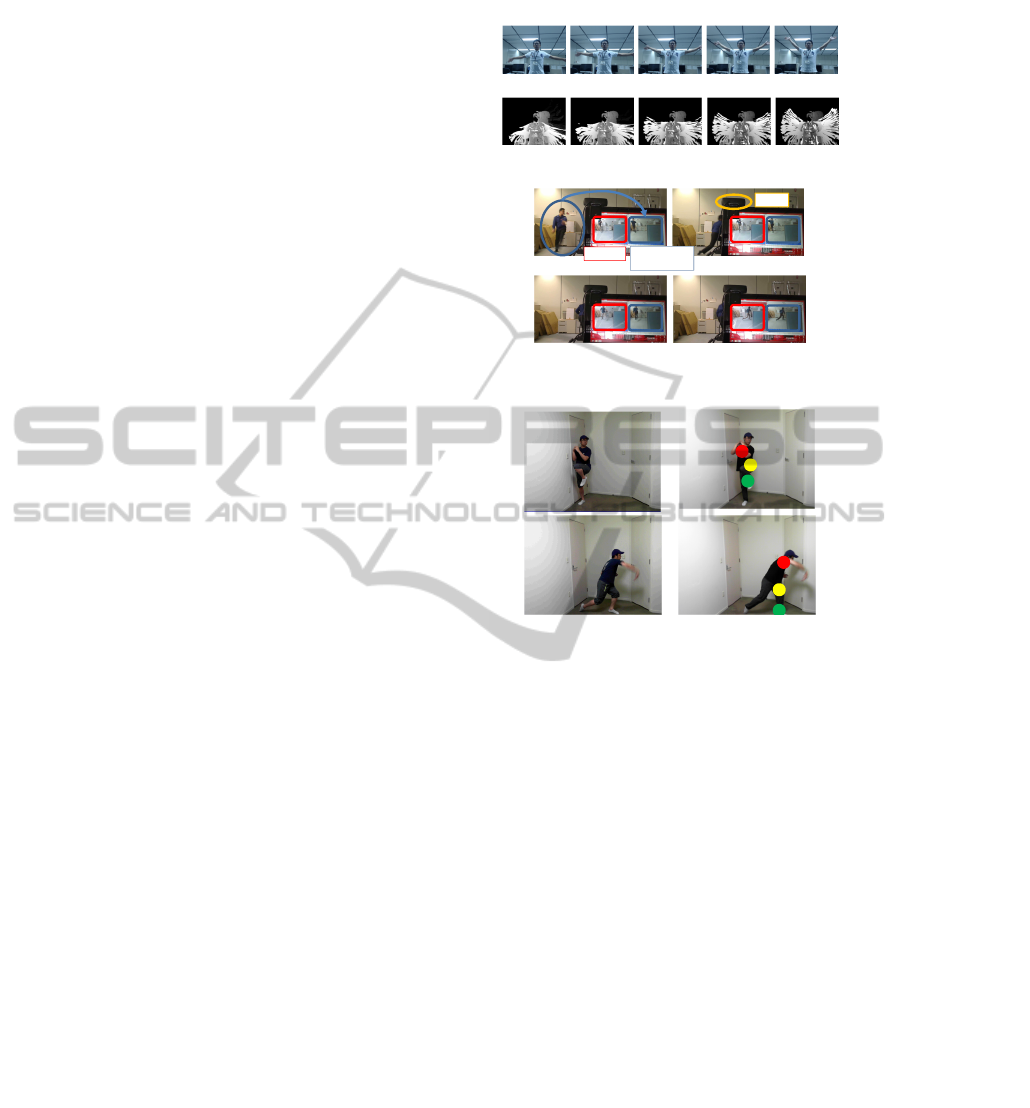
2001), and is employed in the proposed system. Fig-
ure 5 shows an MHI and snapshots of the correspond-
ing image sequence, where the snapshots are shown
from left to right in time order. In the MHI, the value
of each pixel shows how recently a motion was de-
tected on the pixel. Bright (white) pixels denote pixels
at which motions are detected. As the time proceeds
from the most recent motion, the pixels turn dark.
3 RESULTS
Currently, we have not yet verified the motor learn-
ing efficacy obtained with the proposed method. This
section only shows the appropriate motion synchro-
nization and body part estimation it provides.
First, we verified the system provides realtime and
automatic motion synchronization. Fig.6 shows an
example of the results obtained in the verification pro-
cedure. As shown in Fig.6, the trainee’s movement in
front of camera is correctly synchronized with the ref-
erence movement on the display within one second by
using a tablet PC.
We also verified the accuracy with which the sys-
tem estimates body parts for displaying sensor data.
The result sequences are shown in Fig.7. The red, yel-
low and green dots denote arm thigh, and toe, respec-
tively; the left row denotes reference and the right one
denotes synchronized practice sequences. As shown
in Fig.7, the proposed system works well for different
types of clothing worn by trainees. A few errors were
found to have occurred in the body parts estimation,
but the accuracy is good enough for showing sensor
data. So far, we sensors’ output didn’t be used, but
they can be assigned to size and/or color of dot for
intuitive feedback.
4 SUMMARY
In this paper we proposed a new visual feedback
method with the aim of providing visual feedback of
trainee’s movements for effective motor learning. The
method incorporates three main features: (1) auto-
matic temporal synchronization of trainer and trainee
motions, (2) intuitive presentation of sensor data, e.g.
surface electromyography (EMG) and cardiac rate,
based on spatial position of a sensor attached to the
user, and (3) an absence of restrictions on cloth-
ing worn by the user and on illumination conditions.
Future work will include verifying the actual motor
learning obtained with the proposed method.
Original image sequence
MHI sequence
Figure 5: Motion feature MHI.
Reference
Practice
in front of camera
Trainee’s motion
with 1 sec delay
Camera
Figure 6: Realtime processing on tablet PC is verified.
Reference Training
Figure 7: Body parts estimation; red dots denote arm, yel-
low dots denotes thigh, and green dots denotes toe.
REFERENCES
Bobick, A. and Davis, J. (2001). The representation and
recognition of action using temporal templates. IEEE
Trans. PAMI, 23(3).
Choi, W., Mukaida, S., Sekiguchi, H., and Hachimura, K.
(2008). Qunatitative analysis of iaido proficiency by
using motion data. In ICPR.
Chua, P., Crivella, R., Daly, B., Hu, N., Schaaf, R., Ven-
tura, D., Camil, T., Hodgins, J., and Paush, R. (2003).
Training for physical tasks in virtual environments:
Tai chi. In IEEE VR.
Effenberg, A., Fehse, U., and Weber, A. (2011). Movement
sonification: Audiovisual benefits on motor learning.
In The International Conference SKILLS.
Guadagnoli, M., Holcomb, W., and Davis, M. (2002). The
efficacy of video feedback for learning the golf swing.
Journal of Sports Science, 20:615–622.
Wieringen, P. V., Emmen, H., Bootsma, R., Hoogesteger,
M., and Whiting, H. (1989). The effect of videofeed-
back on the learning of the tennis service by interme-
diate players. Journal of Sports Science, 7:156–162.
