Towards Establishing and Maintaining Autonomous
Quadrotor Formations
Audrow J. Nash, Terrill E. Massey, Christopher J. Wesley, Saketh Simha Kosanam
and James M. Conrad
Department of Electrical and Computer Engineering, University of North Carolina at Charlotte,
9201 University City Blvd, Charlotte, U.S.A.
Keywords:
Autonomous, Quadrotor, Unmanned Aerial Vehicle, Vision System, Embedded Processing.
Abstract:
Autonomous aerial formations of multiple quadrotors can be used for payload manipulation and surveillance,
and often require an external system for computation or control, in order to be decentralized. By having cen-
trally controlled quadrotors, swarm applications can be realized without the limitations of an external system.
In this paper, an algorithm is proposed to establish a swarm formation of centrally controlled quadrotors.
First, a method of localization and motion planning is discussed for a single quadrotor. Next, the behavior of
quadrotor swarm formations with centralized control is described. Lastly, the future direction of this research
is explained.
1 INTRODUCTION
A quadrotor is an unmanned aerial vehicle (UAV)
that is composed of four rotating propellers. These
rotating propellers create lift and allow a quadrotor to
take off and land vertically. By varying the speed each
propeller rotates, quadrotors can fly agilely (Gupte
et al., 2012).
Quadrotor applications broadly fall under two
categories: manipulating a payload and surveillance.
For payload manipulation, quadrotors are proposed
for doing tasks such as delivering items; for
example, the company Matternet is building the
infrastructure to use quadrotors to deliver emergency
products to often inaccessible, rural communities
in Africa (George, 2013). Quadrotors have found
surveillance application, including: riotous political
movements, noninvasive inspection of buildings and
public structures (Eschmann, 2012), and unsafe
natural events such as mudslides and volcanoes
(Waite, 2014).
While a solo quadrotor may be practical
for certain tasks, multiple quadrotors cooperating
towards a goal, called swarms, can be especially
useful. Potential applications include: surveillance
of privately property and war zones (Jaimes et al.,
2008) (Culver, 2014), creating a deployable wireless
communication network (Reynaud and Rasheed,
2012) (Alvissalim et al., 2012), and in disaster relief
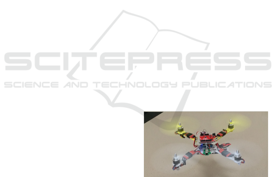
Figure 1: Our quadrotor platform in flight.
(Gupte et al., 2012).
Current swarm research operates by using an
external system which decentralizes control from the
quadrotor. As seen at the University of Pennsylvania
and at ETH Z
¨
urich, quadrotors carry reflective
beacons that are identified by multiple stationary
cameras that view the testing environment. The
video streamed from the cameras is interpreted by
a computer to determine each quadrotor’s location
and state. This information is analyzed and a
command is sent wirelessly to the quadrotors to
actuate (Kushleyev et al., 2013) (Lupashin et al.,
2010). This approach allows for sophisticated
control of the quadrotors: The GRASP laboratories
in the University of Pennsylvania has quadrotors
performing agile swarm maneuvers (Kushleyev et al.,
2013) and flying in formation at aggressive speeds
634
Nash A., Massey T., Wesley C., Kosanam S. and Conrad J..
Towards Establishing and Maintaining Autonomous Quadrotor Formations.
DOI: 10.5220/0005121606340639
In Proceedings of the 11th International Conference on Informatics in Control, Automation and Robotics (ICINCO-2014), pages 634-639
ISBN: 978-989-758-040-6
Copyright
c
2014 SCITEPRESS (Science and Technology Publications, Lda.)
(Jaimes et al., 2008). And at ETH Z
¨
urich,
quadrotors have preformed controlled flips (Lupashin
et al., 2010). However, decentralizing control limits
quadrotor swarms to operation where they are visible
to the external system.
The goal of this research is to create an
autonomous quadrotor swarm with central control.
Therefore, decision making and processing will be
done by the quadrotor swarm. This research is
towards using quadrotor swarms for surveillance,
wireless communication networks, and disaster relief.
The remainder of the paper is organized as
follows: Section 2 discusses the quadrotor platform
devised. Section 3 describes the algorithm for a
quadrotor with centralized control to localize itself
with respect to a reference beacon, and system testing.
Section 4 explains the algorithm designed to leverage
the vision system algorithm to create an autonomous
quadrotor swarm. In section 5, the initial progress
in autonomous flight. Section 6 concludes the paper.
Finally, section 7 discusses future work for this
research.
2 QUADROTOR PLATFORM
The quadrotor system in Figure 2 is composed
of a vision system and flight system. The former
uses optical data to find the quadrotor’s current
location and compares it against a desired position to
generate a movement command. The flight system is
responsible for actuating the movement command and
maintaining stable flight. The full system thus allows
for a quadrotor to move to and maintain a desired
position with respect to reference beacon.
Figure 2: Quadrotor platform system flow chart.
For imaging, a Nintendo Wii controller camera
was extracted, as seen in Figure 3. The Nintendo
Wii controller camera, hence referred to as the Wii
camera, tracks the four highest intensity light sources
and outputs their Cartesian coordinate (X-Y) location.
To reduce ambient light noise, the Wii camera is
paired with an infrared (IR) pass filter.
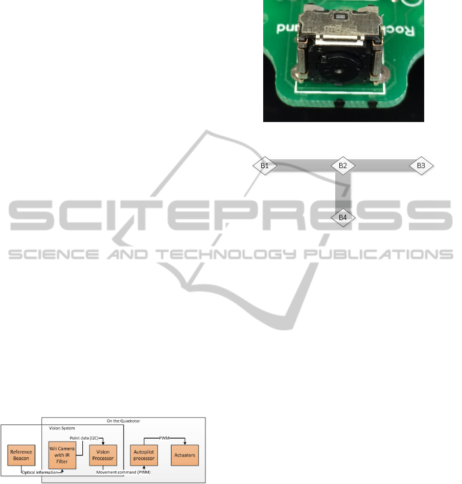
The reference beacon, seen in Figure 4, is
composed of four IR light emitting diodes (LEDs)
denoted by B
i
(i = 1, ..4). To reduce environmental
noise,the Wii camera’s capabilities are saturated by
Figure 3: Nintendo Wiimote camera mounted to quadrotor
frame.
Figure 4: Reference beacon for quadrotor localization.
th beacon’s four light sources. Localization is
accomplished with information obtained from the
three horizontal LEDs B
i
(i = 1, ..3). Because B4 is
not used for localization, B4 will be omitted from
subsequent Figures.
The Wii camera with an IR filter and beacon
are ideal for our application because they allow
conceptual proof of the localization algorithm without
increasing the projects complexity with sophisticated
image processing. It is also a benefit that the camera
system is small, which reduces its footprint and its
weight on the quadrotor.
3 VISION ALGORITHM
The vision processor communicates with the Wii
camera to receive point data for each of the tracked
IR light sources. When looking at the beacon,
the quadrotor localizes itself with respect to the
beacon, and moves towards the desired position. The
movement action is performed so that the quadrotor
can maintain sight of the beacon. When in the desired
position the quadrotor hovers. Should the quadrotor
be unable to find the beacon, it continues to scan in
place for the reference beacon until giving up and
landing.
Since movement and stability are handled by
the autopilot system, if the quadrotor receives no
command to move, it will maintain its altitude and
location. This has allowed us to design the quadrotor
to operate in a move-and-sense pattern. After each
TowardsEstablishingandMaintainingAutonomousQuadrotorFormations
635
executing a movement command, the quadrotor will
counter its lateral velocity. This behavior will happen
several times per second, making for the appearance
of smooth flight as the quadrotor seeks to maintain a
location with respect to the beacon system.
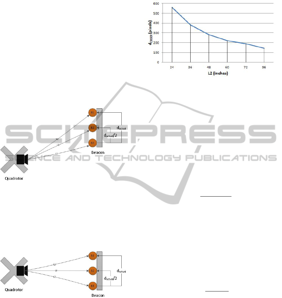
3.1 Optical Metrology
For the quadrotor to determine if it is non orthogonal
to the beacon, such as in Figure 5, the vision
system compares the apparent difference between the
beacon light source pairs: d
obser.B1,B2
and d
obser.B2,B3
.
If the quadrotor is non orthogonal to the beacon,
d
obser.B1,B2
6= d
obser.B2,B3
.
Figure 5: Topography of quadrotor non orthogonal to refer-
ence beacon.
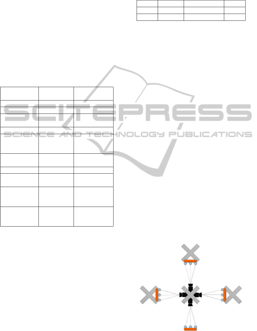
The quadrotor determines that it is orthogonal to
the beacon, such as in Figure 6, when d
obser.B1,B2
=
d
obser.B2,B3
. To generalize the beacon, d
obser.B1.B2
is
related to d
obser
by equation 1. At this point, the
length of the quadrotor from the beacon, defined as
L2, can be related to d
obser
.
Figure 6: Topography of quadrotor orthogonal to reference
beacon.
The quadrotor distance from the beacon was
characterized by comparing L2 to d
obser
, as shown in
Figure 7. In order to make this relationship useful,
the nonlinear relationship was broken up into straight
line approximations. This approach seeks to provide a
computationally inexpensive method to determine the
quadrotors distance, L2, from from the beacon once
orthogonal.
d
obser
= (2 ∗ d
obser.B1,B2
) (1)
Figure 7: L2 vs d
obser
when characterizing Wii camera.
The straight line approximation was accomplished
by relating L2 and d
obser
to slope intercept form, as in
equation 2. In this equation, here m is the slope, and
b is value of d
obser
when the line intersects the d
obser
axis at L2 = 0.
Y = m ∗ X + b ⇒ d
obser
(L2) = m ∗ L2 +b (2)
The slope, m, is determined through equation 3. In
which the change in d
obser
is compared to the change
in L2, which are denoted by denoted by M d
obser
and
M L2, respectively.
m =
M d
obser
(L2)
M L2
(3)
In order to solve for b, the intercept on the d
obser
,
2 is manipulated into equation 4. b was solved
through taking corresponding measured values of
d
obser
and L2 from Figure 7.
b = d
obser
− m ∗ L2 (4)
Finally, the equation 2 was rearranged to create
equation 5. Once m and b are solved for, this equation
solves for the distance the quadrotor is from the
beacon, L2.
L2 =
b − d
obser
m
(5)
For our experiment, we desired a range of twenty
to ninety-six inches, and the beacon was twelve
inches from B1 to B3. We used equations 1-5 to
develop three straight line approximations to fit the
data of Figure 7. With these approximations, the
calculated L2 was within five percent of the actual
distance for the desired range.
3.2 Beacon Testing
To better understand the limitations of the vision
system, it was tested against various IR LED
configurations. During this experiment, we were
ICINCO2014-11thInternationalConferenceonInformaticsinControl,AutomationandRobotics
636
interested to see if the camera sent data in each
configuration and if that data was accurate. For
consistency, the Wii camera system was mounted
at a known distance and facing the reference
beacon. Distance was determined when the beacon
configuration passed basic checks The results of
camera limits are shown in Table 1.
Table 1: System response to various beacon light
source configurations. Note the following: Under the
LED Con f iguration column, o denotes an LED emitting
towards the Wii camera. In the Data Sent column, In. sig-
nifies data has been received inconsistently. All rotations
and inversions of beacon configurations were tested but one
case is shown to save space.
LED Data Sent Data Accurate
Configuration (Yes/No/In.) (Yes/No)
o No
o o No
o No
o
o o o No
o
o No
o
o o o Yes Yes
o
o o o o Yes No
o Yes No
o o o
o
o o o In. No
o
o
o o o In. No
o
As expected, the vision system did not send data
until there were four light sources. When there are
four LEDs on the horizontal line or five light sources,
the system was unable to determine which light
sources to use, and the data was incorrect. From these
results, we learned that increased software filtering
can reduce environmental noise.
The vision system’s was tested under varying light
conditions. It was assumed that by using the IR
pass filter with the Wii camera that indoor lighting
would have no noticeable impact. To validate this, the
extremes of indoor lighting were tested: no light, full
lighting. For both lighting conditions, the full range
of the vision system was tested.
It can be observed from the results of Table
2 that for both lights on and off the Wii camera
performed in the range it was designed for. Therefore,
environmental lighting conditions have no effect on
Table 2: Effect of ambient light on vision system range.
Lights Min (in) Maximum (in) Range
On 20 96 100%
Off 20 96 100%
the vision system’s ability to gain optical information
from the reference beacon.
4 SWARM ALGORITHM
The purpose of the swarm algorithm is to accept
the movement commands from the vision algorithm
and communicate this information to respective
quadrotors in the network. The communication of the
movement commands will be established through a
wireless medium with a wireless transceiver.
4.1 Network Topology
In the swarm network topology,the coordinator is
responsible for assigning movement commands of all
quadrotors in the immediate area. The coordinator
will have only Wii camera systems on its platform.
The followers in the swarm network only contain IR
beacons on their platform, and perform commands
received from the coordinator.
The swarm topology in Figure 8 shows the
topology of a cluster with three followers, a
coordinator, and a fixed beacon. All following
quadrotors immediately adjacent to a coordinator are
considered to be part of that coordinator’s cluster.
Within its cluster, a coordinator obtains position
information from all the local followers using the
process explained in the Vision Algorithm. This
information is used to issue a movement command
through wireless transmission in order to maintain
swarm formations.
Figure 8: Network Topology of Swarm Cluster.
TowardsEstablishingandMaintainingAutonomousQuadrotorFormations
637
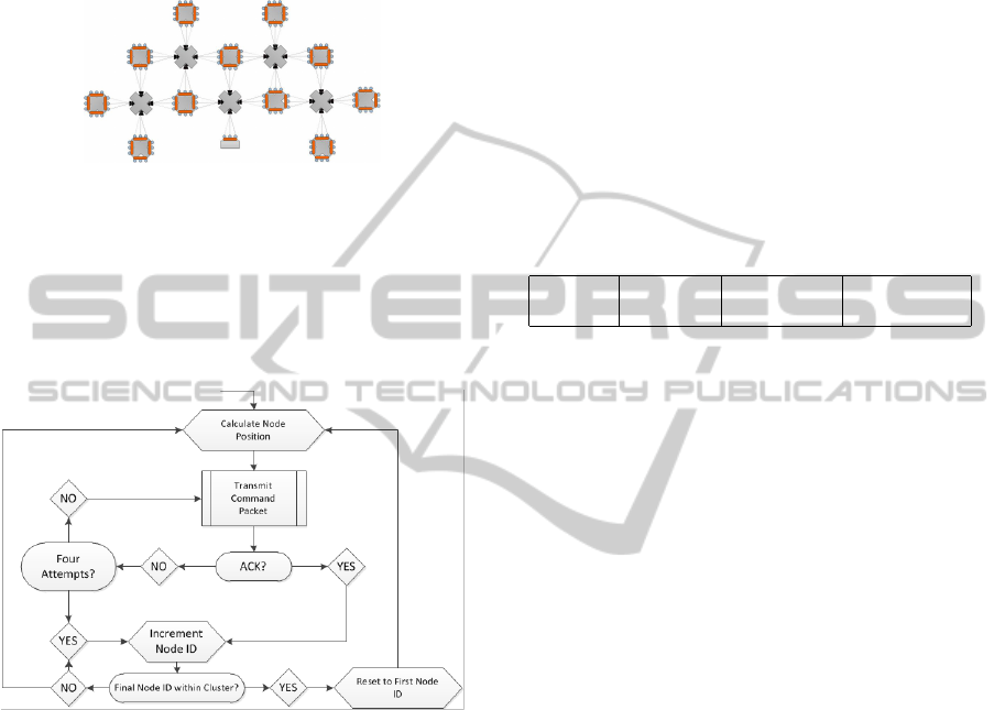
The algorithm scales to accommodate larger
swarm formations by adding additional clusters, such
as the one illustrated in Figure 9. A priority weighted
algorithm will be used to resolve conflicts in the case
of a follower receiving conflicting commands from
multiple coordinators.
Figure 9: Network Topology of Multiple Clusters.
4.2 Routing Algorithm
The decision process performed by the coordinator in
order to accurately send movement commands to all
following quadrotors in the cluster is referred to as the
Cluster Routing Algorithm (CRA).
Figure 10: Cluster Routing Algorithm.
The purpose of the CRA is to issue commands
to all followers within the cluster. The algorithm
ensures that all commands are issued to the
respective followers in a reliable manner, and that all
followers receive equal amount of attention from their
respective coordinator. The elements of the CRA, as
depicted by Figure 10, are described in detail below.
Initialization. The coordinator assigns a node ID to
the follower.
Calculate Follower Position. The position of
follower of interest is calculated.
Transmit Command Node Packet. The movement
commands are wirelessly transmitted to the
appropriate follower in the form of a packet.
The packet structure of the transmitted data is shown
in Table 3.
Acknowledgment. The coordinator waits for a
period of time for an acknowledgment from the
respective follower to confirm the command was
received. If the coordinator fails to receive an
acknowledgment from the follower, it will retransmit
the command packet. This process will continue for
four times until which the coordinator will direct its
attention to the next follower.
Increment Node ID. The coordinator increments the
node ID so that it may focus on the next follower
within the cluster.
4.3 Transmission Structure
The packet structure used in the transmission of data
from the coordinator to followers as described in the
routing algorithm section is shown in Table 3.
Table 3: Data frame structure of the transmitter.
Header Node ID Movement Error check
command
The data packet to be sent contains a header
field, a unique node ID exclusive to each quadrotor,
a movement command, and an error check is
incorporated. An explanation of each of the Fields
within the packet structure follows.
Header. Indicate the starting delimiter of the data
packet.
Node ID. Address of the desired destination.
Movement Command. Directs follower movement.
Error check. A checksum sequence is used for error
detection within the packet.
5 AUTONOMOUS PROGRESS
There have been various small-scale tests performed
with the control system, and information regarding
the methodology of testing such a system has been
gained. Our first step was to emulate the radio
controller via a micro controller. Next, a suitable test
environment and safe testing procedure was created
for the quadrotor autonomous flight.
After securing the quadrotor to the test
environment, the quadrotor was programmed to
lift off autonomously. Instead of the quadrotor rising
up in a strictly vertical motion, the quadrotor would
fly in an angled direction depending on the state of the
motors. After a short period of time, the quadrotor’s
flight control unit would stabilize and compensate for
the motion of the quadrotor. Through this testing, it
was validated that a larger testing environment will
be needed for more advanced autonomous flight.
ICINCO2014-11thInternationalConferenceonInformaticsinControl,AutomationandRobotics
638

Figure 11: Basic autonomous test environment. a) Quadro-
tor. b) Platform to raise quadrotor. c) Tethers to each
quadrotor arm d) Foam padding. e) Researcher workstation
for programming. Note that tethers parachute cord which
allows the researcher to work safely at the researcher work-
station while quadrotor is testing
6 CONCLUSION
This paper presents the value of conducting research
into autonomous quadrotor swarm formations.
It also examines others’ current research into
quadrotor swarm formations and the drawbacks
of decentralizing quadrotor control. The designs
explained in this paper are towards autonomous
quadrotor swarm control for uses that decentralized
quadrotor systems are not optimal.
Our efforts have been placed into developing
an autonomous control system integrated with an
on-board vision system, explicating swarm formation
algorithm, and determining the methods and
precautions for safely testing quadrotor autonomous
flight.
The limitations of our design are as follows:
First, changes in quadrotor position from commands
are small and safe. This results in a swarm that
does not move agilely. Second, the vision system
can determine it’s distance to the beacon when
the quadrotor is orthogonal to the coordinator, thus
restricting formation options for the swarm.
7 FUTURE WORK
A larger and safer testing environment is necessary
for further testing. The quadrotor test environment
will be large enough for swarm formations and have
foam padded floors and nylon fabric walls. Several
cameras will facilitate accurate observation for testing
and documentation.
Our team will implement full autonomous control
by incrementing autonomous behavior. Our system
will accommodate multiple quadrotors, and will have
the capability of forming a network and will employ
the vision system to establish and maintain swarm
formations. In addition, the algorithm discussed will
be implemented with a more powerful and practical
vision system, eliminating the swarm’s dependence
on IR beacons.
ACKNOWLEDGEMENTS
The authors would like to acknowledge North
Carolina Space Grant Consortium for their financial
assistance to conduct this research.
REFERENCES
Alvissalim, M. S., Zaman, B., Hafizh, Z., Ma’sum, M., Jati,
G., Jatmiko, W., and Mursanto, P. (2012). Swarm
quadrotor robots for telecommunication network cov-
erage area expansion in disaster area. In SICE An-
nual Conference (SICE), 2012 Proceedings of, pages
2256–2261. IEEE.
Culver, K. B. (2014). From battlefield to newsroom: Eth-
ical implications of drone technology in journalism.
Journal of Mass Media Ethics, 29(1):52–64.
Eschmann, C. Kuo, C. B. (2012). Unmanned aircraft sys-
tems for remote building inspection and monitoring.
pages 1–8.
George, A. (2013). Forget roads, drones are the future of
goods transport. New Scientist, 219(2933):27.
Gupte, S., Mohandas, P. I. T., and Conrad, J. M. (2012).
A survey of quadrotor unmanned aerial vehicles. In
Southeastcon, 2012 Proceedings of IEEE, pages 1–6.
IEEE.
Jaimes, A., Kota, S., and Gomez, J. (2008). An approach
to surveillance an area using swarm of fixed wing and
quad-rotor unmanned aerial vehicles uav (s). In Sys-
tem of Systems Engineering, 2008. SoSE’08. IEEE In-
ternational Conference on, pages 1–6. IEEE.
Kushleyev, A., Mellinger, D., Powers, C., and Kumar, V.
(2013). Towards a swarm of agile micro quadrotors.
Autonomous Robots, 35(4):287–300.
Lupashin, S., Schollig, A., Sherback, M., and D’Andrea,
R. (2010). A simple learning strategy for high-speed
quadrocopter multi-flips. In Robotics and Automa-
tion (ICRA), 2010 IEEE International Conference on,
pages 1642–1648. IEEE.
Reynaud, L. and Rasheed, T. (2012). Deployable aerial
communication networks: challenges for futuristic ap-
plications. ACM MSWIM (International Conference
on Modeling, Analysis and Simulation of Wireless and
Mobile Systems), pages 9–16.
Waite, M. (2014). Journalism with flying robots.
XRDS: Crossroads, The ACM Magazine for Students,
20(3):28–31.
TowardsEstablishingandMaintainingAutonomousQuadrotorFormations
639
