Methods to Reduce the Resonant Stresses Level of Gas Turbine
Engines Compressor Rotor Wheels
Grigorii M. Popov, Aleksandr O. Shklovets, Aleksandr I. Ermakov and Daria A. Kolmakova
Department of Theory of Engine for Flying Vehicles, 34 Samara State Aerospace University (SSAU),
Samara, Russian Federation
Keywords: Gas Turbine Engine, Compressor, Blade, Support, Ansys, CFX, Forced Oscillations, Optimization.
Abstract: The approaches to reducing the alternating stresses in the compressor blades, arising at a resonance, are
discussed in paper. Maximum alternating stresses in blades of the fifth stage of intermediate pressure
compressor (IPC, that operating under the gas flow circumferential variation conditions, are defined on the
basis of the forced blade oscillations calculation method. Parametric CFD-model which allows to introduce
different stagger angles and circumferentially alternating blade pitch at the guide vanes of IPC fifth stage
was created to reduce the stresses. The flow circumferential variation was reduced by changing these
parameters and as a consequence the resonant stresses were decreased by more than 2.5 times.
1 INTRODUCTION
Circumferential variation of the gas flow in the
channel of gas-turbine engine (GTE) is the major
factor, exciting blades oscillations, which lead to
blade fatigue destructions (Hynes, Greitzer, 1987).
The problem is compounded by the fact that
circumferential variation of the gas flow is unsteady
and caused by large numbers of both upstream and
downstream channel elements (Kuz'michev,
Morozov, 1991). Therefore the problem of reduction
of blades gas-dynamic excitation is extremely
complex and usually solved by using a large number
of experiments (Kaya, 2003).
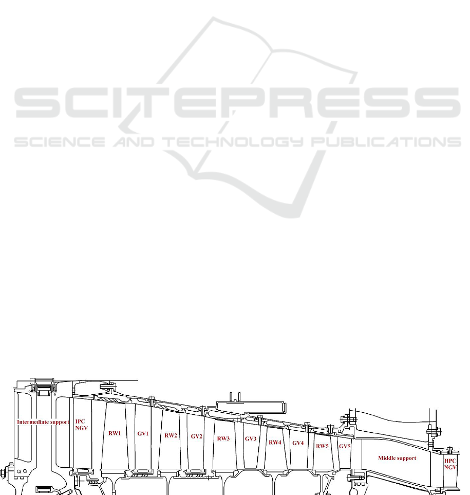
The blades of the fifth rotor wheel (RW5) of
five-stage intermediate pressure compressor (IPC) of
gas turbine engine was object of research in this
paper (Figure 1).
The casing of the engine middle support is
located downstream the fifth compressor stage. High
pressure compressor is located after the support
casing. There are seven unevenly distributed racks
of different cross-sections in the channel of support
casing. (Figure 2). These racks are the cause of
circumferential variation of the gas flow in GTE
passage, which leads to increased dynamic stresses
in the fifth RW blades, as a consequence, to its
breakage.
The goal of this work was to reduce the dynamic
stresses in the rotor blades of the IPC fifth stage by
means of the blades reprofiling and circumferential
variation flow reduction.
Figure 1: The scheme of investigated compressor blading.
619
M. Popov G., O. Shklovets A., I. Ermakov A. and A. Kolmakova D..
Methods to Reduce the Resonant Stresses Level of Gas Turbine Engines Compressor Rotor Wheels.
DOI: 10.5220/0005108706190624
In Proceedings of the 4th International Conference on Simulation and Modeling Methodologies, Technologies and Applications (SIMULTECH-2014),
pages 619-624
ISBN: 978-989-758-038-3
Copyright
c
2014 SCITEPRESS (Science and Technology Publications, Lda.)
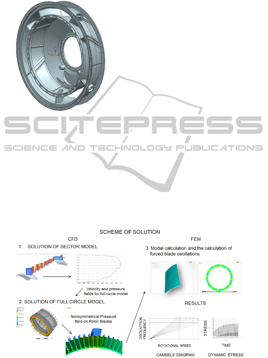
Figure 2: Casing of middle support.
2 METHOD FOR DYNAMIC
STRESSES CALCULATION
Method for dynamic stresses calculation in RW
blades of the IPC fifth stage was created at the first
stage (Shklovets, Popov, Kolmakova, 2012). This
method consisted of four stages.
1. Calculation at the required engine mode (take-
off mode and idle mode) is performed for the IPC
sector model in the software package NUMECA
Fine Turbo. The sector model also comprises inlet
guide vane (IGV) of high pressure compressor
(HPC), middle and intermediate engine supports.
Radial profiles of total pressure, total temperature
and flow direction in the section behind the rotor
wheel of IPC fourth stage were determined as the
result of this calculation.
2. The “full circle” compressor model calculation
with boundary conditions obtained in the IPC sector
model calculation is performed in the software
package Ansys CFX (Bochkarev, Dmitriev, Kulagin,
Makeenko, Mosoulin, Mossoulin, 1993). Full circle
model consists of the following blade rows: IPC
fourth guide vane (GV4), fifth rotor wheel, fifth
guide vane (GV5), middle support and HPC inlet
guide vane (IGV). Gas-dynamic load having an
effect at the IPC fifth RW blades and considering
gas flow circumferential variation caused by the
middle support racks was determined in this
calculation.
3. The calculation of the fifth RW blades natural
frequencies is performed in the software package
Ansys Mechanical. Based on this calculation, RW
frequency diagram construction and IPC rotor
speeds, at which the resonance may occur, are
carried out.
4. Gas load is represented as a combination of
backward traveling waves of load (harmonic waves)
using the object-oriented programming language
APDL, built in Ansys. Further dynamic calculation
at the resonance mode in resonance with the most
dangerous harmonic is performed. This method is
presented schematically in Figure 3.
Figure 3: The scheme of method for calculation compressor rotor blades forced oscillations.
SIMULTECH2014-4thInternationalConferenceonSimulationandModelingMethodologies,Technologiesand
Applications
620

3 THE MEASURES FOR BLADES
ALTERNATING STRESSES
MITIGATION
The following areas were selected as measures to
reduce the resonant stresses level:
the usage of the blades with special Shvarov’s
profile at last rotor wheel;
the usage of the guide vane in front of the
middle support, with the blades set having
different stagger angles and with
circumferentially alternating blade pitch.
Also, special attention was paid to the fact that
the number of blades with stagger angles different
from the standard should be as low as possible.
Parameterization of the full circle compressor
model was carried out for the introduction GV5
different stagger angles and circumferentially
alternating blade pitch.
At the first stage of creating a parametric model
the support racks and blades of GV5 were divided
into groups. For this purpose the development
drawing of the blade row in the circumferential
direction was carried out. The assumption that for
several blade groups will be given the same stagger
angle and blade pitch parameters was made for IPC
GV5 blades. When introducing the different stagger
angles the key factor was the minimum number of
changeable blades as the manufacturing a large
number of blades with different geometry greatly
increase the production costs. The quantity of the
variable blades in group was specified by the
number in brackets (Table 1).
Then, the maximum blade stagger angle within
the joint groups was determined. The stagger angle
was not changed for the GV5 blades located in the
racks plane of symmetry, the first and last blades in
the group. Changing of the stagger angles within the
groups were performed linearly. Blades arranged on
opposite sides of the racks plane of symmetry were
rotated in opposite directions relative to the initial
position (Figure 4). Moreover the blades located
closer to the front were rotated by a larger angle. If
the blade was rotated on closing (increase of the
stagger angle) before the angle value there is a sign
"+" if on opening (decrease of the stagger angle) -
sign "-".
The number of removable blades was not
restricted when blade pitch were changed. Parameter
of alternating blade pitch was set within 0.35...0.35
of the base pitch. The sign "-" means that in the
region between the blades the pitch is decreased,
while "+" - the pitch is increased. The number
indicates the maximum blade pitch increase
(decrease) in the group in relative values from the
nominal pitch with evenly spaced blades. Position of
extreme blades in groups was not changed when
introducing the circumferentially alternating blade
pitch. The law of pitch changing was also linear.
Thus, the universal parametric model which allows
to the introduction different stagger angles and
circumferentially alternating blade pitch at the IPC
fifth stage was created.
4 OPTIMIZATION
CALCULATIONS OF THE
DYNAMIC STRESSES IN THE
IPC FIFTH ROTOR BLADE
Calculations of dynamic stress for 11 variants of the
IPC fifth stage were performed using a parametric
model (Shklovets, Popov, Kolmakova, 2013). Blade
with a special Shvarov’s profile was used as the fifth
stage rotor blade in all the variants. The variants
differed from each in values of different stagger
angles and alternating blade pitch parameters of IPC
GV5. At the same time the first variant corresponded
to the base GV5.
The calculation results of the dynamic stresses
which arise at a resonance with the strongest 12th
harmonic, parameters of each variant as well as the
total number of GV variable blades of IPC fifth
stage are shown in Table 1.
Figure 4: Rotation scheme of guide vane blades.
MethodstoReducetheResonantStressesLevelofGasTurbineEnginesCompressorRotorWheels
621
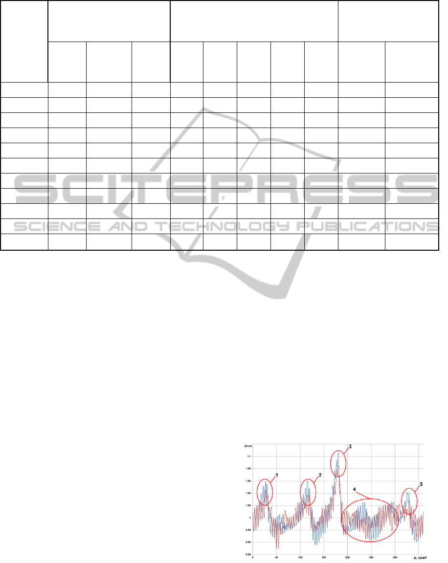
Table 1: The results of the parametric IPC model calculation.
Variant
number
Parameter of different stagger
angles, maximum stagger
angles (number of blades) for
the groups:
Parameter of alternating blade pitch for the
groups:
2, 5, 6 1, 3, 7 4 (3) 1, 7 2, 6 3 4 5
Number
of
variable
blades
Dynamic
stresses
MPa
1 0 0 0 0 0 0 0 0 0 86.7
2 0 0 0 0.3 0.3 0.3 0.3 0.3 0 115.98
3 3 (6) 3 (6) 3 (8) 0 0 0 0 0 42 43.791
4 3 (6) 3 (6) 3 (8) 0.3 0.3 0.3 0.3 0.3 42 31.877
5 3 (6) 6 (6) 9 (8) 0 0 0 0 0 42 37.536
6 0 0 0 0.35 0.35 0.35 0.35 0.35 0 86.95
7 0 0 0 -0.3 -0.3 -0.3 -0.3 -0.3 0 105.94
8 0 0 0 -0.15 -0.15 -0.15 -0.15 -0.15 0 137.741
9 6 (2) 6 (2) 6 (2) 0 0 0 0 0 14 46.737
10 0 6 (2) 6 (2) 0 0 0 0 0 8 57.214
11 6 (2) 6 (2) 6 (4) 0 0 0 0 0 16 44.426
From the data presented in Table 1, it is clear
that a significant reduction of the dynamic stresses
in the RW of IPC fifth stage at resonance with the
12th harmonic was achieved when applying the
Shvarov’s profile at rotor blades and introducing the
different stagger angles at GV of the IPC fifth stage.
Thus the level of dynamic stresses at resonance with
the 12th harmonic was 86.7 MPa when using RW5
blades with the Shvarov’s profile and the base GV5.
And when the Shvarov’s profile at RW5 and also
different stagger angles and alternating blade pitch
parameters of IPC GV5 were used (variant No 4 in
Table 1, changeable GV5 blades value is 42) the
level of dynamic stresses at resonance with the 12th
harmonic was 31.9 MPa (reduced by 2.7 times).
However, the usage of RW5 blades with the
Shvarov’s profile and GV5 blades with different
stagger angles (variant No 9 in Table 1, changeable
GV5 blades value is only 14) the level of dynamic
stress is not much large than in variant No 4 – 46.7
MPa (reduced by 1.85 times).
4.1 Analysis of Circumferential
Variation Calculation for the IPC
Fifth Guide Vane Variants Giving
the Largest Dynamic Stresses
Reduction
The relative static pressure profiles in the cross
section following the IPC RW5 at mid-span for the
basic compressor case and compressor variant No 4
are shown in Figure 5 for the idle mode. The Figure
5 shows the basic version in blue and modernized
(variant No 4) – in red. Marked pressure peaks
correspond to the support racks and areas near them.
Figure 5: Relative static pressure variation in the section
following the IPC RW5 at mid-span.
SIMULTECH2014-4thInternationalConferenceonSimulationandModelingMethodologies,Technologiesand
Applications
622
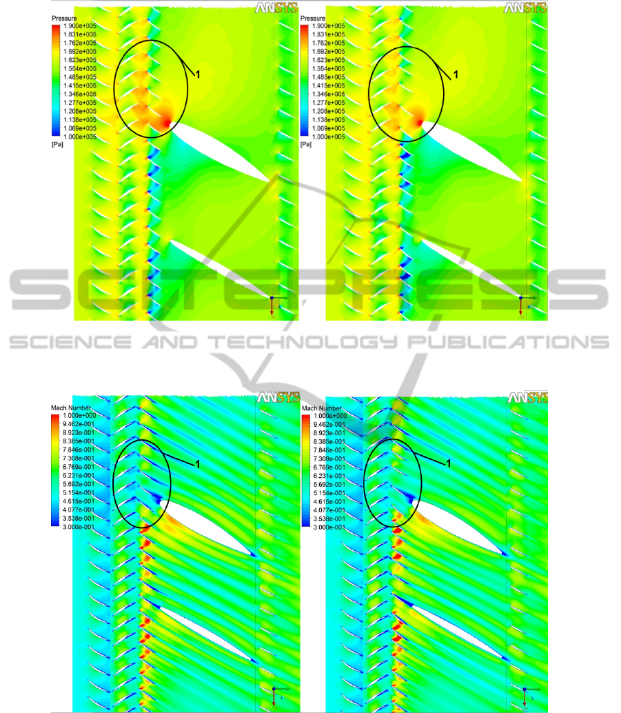
Base variant Variant No4
Figure 6: Static pressure field close to support rack in area 1.
Base variant Variant No4
Figure 7: Mach number field close to lower support rack.
Comparison of static pressure distribution fields
at mid-span the base compressor case and variant No
4 (Table 1) at area 1 are shown in Figure 6. A
similar comparison for the flow Mach number is
shown in Figure 7.
Apparently from the presented graphs and static
pressure distribution fields static pressure peaks
MethodstoReducetheResonantStressesLevelofGasTurbineEnginesCompressorRotorWheels
623

decrease is observed for modernized variant (No 4)
compared to the base compressor case at the areas 1,
3 and 5. In addition, the more periodicity and more
uniform flow field is achieved for all specific areas.
5 CONCLUSIONS
Thus, the following results were achieved in the
course of this work:
1. Significant reduction of the dynamic stresses
in the IPC fifth rotor wheel at resonance with the
twelfth harmonic was achieved. More specifically,
the dynamic stresses were reduced by one half
compared with the RW5 with Shvarov’s profile and
base variant of GV5.
2. It was found that the different blades stagger
angles and alternating blade pitch introduction
allows to "flatten" the circumferential variation in
the cross section following the IPC RW5.
ACKNOWLEDGEMENTS
This work was financially supported by the Ministry
of education and science based on the Government
of the Russian Federation Decree of 09.04.2010 №
218 (code theme 2013-218-04-4777) and in the
framework of the implementation of the Program of
increasing the competitiveness of SSAU among the
world’s leading scientific and educational centers for
2013-2020 years.
REFERENCES
Hynes, T.P., Greitzer, E. M. 1987. A method for assessing
effects of circumferential flow distortion on
compressor stability. In Journal of Turbomachinery
vol. 109 (3), pp. 371-379.
Kuz'michev, V.S., Morozov, M.A. 1991. Conception of
method of pattern recognition of working process of
gas turbine engines in conditions of information
deficit. In Izvestiya VUZ: Aviatsionnaya Tekhnika
vol.(3), pp. 44 – 49.
Kaya, D. 2003. Experimental study on regaining the
tangential velocity energy of axial flow pump. In
Energy Conversion and Management vol. 44 (11), pp.
1817-1829.
Shklovets A.O., Popov G.M., Kolmakova D.A. 2012.
Issues of numerical investigations of forced axial
compressor blades oscillations. In Vestnik
dvigatelestroeniya vol. 2, pp. 223-227
Bochkarev, S.K., Dmitriev, A.Ya., Kulagin, V.V.,
Makeenko, S.V., Mosoulin, V.V., Mossoulin, A.A.
1993. Experience and problems of computer aided
thermogasdynamic analysis of testing results for gas-
turbine engines with complex schemes. In Izvestiya
Vysshikh Uchebnykh Zavedenij. Aviatsionnaya
Tekhnika, vol. 2, pp. 68-70.
Shklovets A.O., Popov G.M., Kolmakova D.A. 2013.
Optimization of the compressor stage blading of gas
turbine engine to ensure the dynamic strength in rotor
blade row. In Vestnik dvigatelestroeniya vol. 2, pp.
192-197.
SIMULTECH2014-4thInternationalConferenceonSimulationandModelingMethodologies,Technologiesand
Applications
624
