
Heat Transfer Enhancement of the Film Flow Falling
along Vertical Fluted Plates
Shouta Satou and Takahiro Adachi
Department of Mechanical Engineering, Akita University, Tegata-gakuen1-1, Akita, 010-8502, Japan
Keywords: Liquid Film Flow, Heat Transfer, Graetz-Nusselt's Problem, CLSVOF, GFM.
Abstract: Heat transfer enhancement of the film flow falling along vertical rectangular fluted plates is investigated in
this study. We have calculated the temporal evolution of the film flow by using the CLSVOF and GF
methods, and obtained the steady state film and velocity distributions. It is found that the film flow goes
inside the fluted part due to the effect of the surface tension for the fluted plate and the thickness near the
fluted edge is thinner. This may lead to the heat transfer enhancement. Therefore, the temperature
distribution is calculated in the thermally inlet region, which corresponds to the problem of two-phase
version of the well-known Graetz-Nusselt's problem. Finally, we show the relation among the heat transfer,
fluted geometries and the surface tension effect.
1 INTRODUCTION
Absorption refrigeration systems have taken an
increasing interest due to the global warming
problem. The systems are regarded not only as
environmentally friendly alternatives to the
fluorocarbon-based systems, but also as energy
efficient heating and cooling technology (Berlitz et
al., 1999). An absorber is a major component in the
absorption refrigeration systems because it greatly
affects the overall system performance. There are
two types of absorbers. One is a plate-type absorber,
while the other is a tube-type one. Generally, the
plate-type absorber is superior to the tube-type one
from the point of view of lightness, compactness,
maintenance, etc. under the same operating
conditions. Therefore we focus our attention on the
plate-type absorber in this study.
In the plate-type absorber, a thin liquid film flow
is observed and plays an important role in heat and
mass transfer. Therefore, the characteristics of the
thin falling liquid film along a vertical flat plate and
the corresponding temperature characteristics have
been extensively investigated both experimentally
and numerically (Kapitza and Kapitza, 1965, Kranz
and Goren, 1971, Pierson and Whitaker, 1977).
Recently, increasing the demand for smaller
space and lower noise level tends to make
representative size and velocity smaller. Therefore,
it is important to enhance the heat transfer in the
laminar flow regime. In order to enhance the heat
transfer, rectangular, triangular or sinusoidal fluted
parts along the stream-wise direction have been
established on the plate. This is because the liquid
film spreads as thinly as possible over the plate
surface since strong surface tension aids in the
removal of film from the top to bottom of the fluted
parts, thereby producing a very thin liquid film. This
is called a drainage effect (Gregorig, 1954,
Kedzierski and Webb, 1990).
However, it is difficult to clarify the detailed
mechanism of the heat transfer enhancement,
because the film flow has thin, three-dimensional
and unsteady behaviour. Actually, it has been shown
that the film flow on the flat plate behaved like a
wave and thickness of the film flow became thinner
locally in the wavy flow regime, which leads to the
enhance of the heat transfer enhancement (Miyara,
2000, 2001, Al-Sibai, 2002). In case of the fluted
plate, the situation must be more complicated. So, it
is greatly depends on numerical calculations to
clarify the flow and temperature characteristics.
In this study, we numerically investigate the thin
liquid film flow on the vertical rectangular fluted
plates in laminar flow resume. Our objective is to
clarify effects of grooved geometries and surface
tension on both the flow patterns and the heat
transfer by setting the fluted parts on the vertical flat
plate. Then, we treat our study under the well-known
607
Satou S. and Adachi T..
Heat Transfer Enhancement of the Film Flow Falling along Vertical Fluted Plates.
DOI: 10.5220/0005104306070612
In Proceedings of the 4th International Conference on Simulation and Modeling Methodologies, Technologies and Applications (SIMULTECH-2014),
pages 607-612
ISBN: 978-989-758-038-3
Copyright
c
2014 SCITEPRESS (Science and Technology Publications, Lda.)

Graetz-Nusselt's problem. This means that the film
flow is three-dimensional and fully developed in the
stream-wise direction, while the temperature is
developing in the thermally inlet region. We will try
to show the relation among the heat transfer, fluted
geometries and the surface tension effect.
2 MATHEMATICAL
FORMULATION
2.1 Mathematical Model
We consider a two-phase flow along a fluted plate as
shown in Fig.1 (a). We take a half of groove which
is enclosed by broken lines in Fig.1 (a). Figure 1 (b)
depicts the plate cross section taken from Fig.1 (a)
and indicates the geometric quantities that define its
shape. The plate consists of smooth part of width
∗
,
fluted part of width
∗
and height
∗
measured from
the bottom of the groove, which is symmetric with
respect to the broken lines in Fig.1 (b). We pay
attention only to the typical cross-section shown in
Fig.1 (b) by considering symmetric condition.
2.2 Governing Equations
The flow is assumed to be three-dimensional,
incompressible and fully developed steady state. In
addition, a velocity is assumed to be unchanged in z
direction. It is impossible to find the liquid film flow
distribution along the fluted plate surface at steady
state in advance, so we calculate the unsteady
momentum equations in x and y directions. Next, we
calculate the momentum equations in z direction
under the steady condition due to fully developed
flow. After that, the film flow distribution is
calculated by using the velocity profiles. Finally, the
energy equation in the thermally inlet region is
solved. This is recognized as a problem of two-phase
version of the well-known Graetz-Nusselt's problem.
The governing equations for the velocity and
pressure are written in non-dimensional forms as
0,
(1)
1
2
,
(2)
(a) (b)
Figure 1: Physical model and coordinates.
1
2
,
(3)
1
(4)
where velocity gradient in z direction is ignored such
as
⁄
⁄
⁄
0 in the equations
(1), (2), (3) and (4) because of assumption as
velocity u is unchanged in z direction.
The governing equations for the temperature is
written in non-dimensional forms as
1
(5)
where heat conduction term in z direction is omitted
in the equation (5) because heat conduction in z
direction is smaller than one in x and y directions.
All the variables have been non-dimensionalized
using a characteristic length
∗
, a film surface
velocity
∗
, the density of the liquid phase
∗
, the
temperature on the plate
∗
and the temperature in
gas phase
∗
as
∗
∗
,
∗
∗
,
∗
∗
,
∗
∗
,
∗
∗
,
∗
∗
,
∗
∗
∗
,
∗
∗
∗
,
∗
∗
∗
∗
(6)
where we represent physical quantities with their
dimensions by attaching a superscript * to them.
We consider that the density, viscosity, thermal
conductivity and specific heat change
discontinuously across the interface between the
liquid and gas phases and are written as
1
,
(7)
where H is the discontinuous step function
(Heaviside function) defined as
SIMULTECH2014-4thInternationalConferenceonSimulationandModelingMethodologies,Technologiesand
Applications
608

0, 0
1, 0
(8)
where is the level-set function which is defined as
a distance function between the center point of
calculation cell and gas-liquid interface. In addition,
the density, viscosity, thermal conductivity and
specific heat are non-dimensionalized based on the
values of liquid phase, and they are unity in the
liquid phase, defined as follows in the gas phase
∗
∗
,
∗
∗
,
∗
∗
,
∗
∗
(9)
where subscript l is physical properties in liquid
phase and v is physical properties in gas phase.
Non-dimensional geometric parameters are
defined as
∗
∗
,
∗
∗
,
∗
∗
.
(10)
Non-dimensional parameters in equations are
Reynolds number Re and Prandtl number Pr,
defined as
∗
∗
∗
,
∗
∗
(11)
where
l
*
is kinematic viscosity of the liquid phase
and
l
* the temperature conductivity.
Because there is a special relation between
Froude number and Reynolds number(Adachi, 2013),
the Froude number is defined as
1
2
1
1
21
1
(12)
where
∗
∗
⁄
is the computational domain in y
direction as shown in Fig. 1(b) and h=4 in this study.
2.3 Boundary Conditions
The conservation equations (1)-(4) for each phase
are coupled through the discontinuous jump
conditions at the interface written in non-
dimensional forms as
0,
(13a)
∙
1
∙
(13b)
where
is a curvature of the film surface, n is an
unit normal vector at the interface from the gas
phase to the liquid phase and Bo is bond number
defined as
∗
∗
∗
∗
(13c)
where
l
* is the surface tension coefficient and g* is
the gravitational acceleration. It should be noted that
the temperature is assumed to be constant in the gas
phase because it plays a model of mass transfer in
the gas phase simultaneously. So, the temperature is
a saturation constant and unity in the gas phase.
The boundary conditions on the plate surface are
given by
0, 0, 0, 0.
(14)
In addition, the flow is assumed to be symmetric
along the broken lines indicated in Fig.1 (b). Then
the symmetry conditions are expressed as
0.
(15)
Finally, the Sommerfeld radiation condition is
imposed at the boundary of the computational
domain at y=h as
0
(16)
where U is a advection velocity adopted as U=1 in
this study.
3 NUMERICAL METHOD
In order to calculate the fully developed film flow,
we calculate the velocity u by solving equations (1)-
(3) under the boundary condition given by equations
(13)-(16). Then we use Highly Simplified Marker
and Cell (HSMAC) method and Ghost Fluid (GF)
method (Kang et al., 2000 and Gibou et al., 2002).
HSMAC method is used to be able to calculate
velocity and pressure avoiding the calculation of
Poisson equation and GF method is used to obtain
sharp changes of some physical quantities across the
interface between the liquid and gas phases, where a
semi-implicit method is used for the calculation of
the viscous term (Li et al., 1998).
In addition, we use a Coupled Level Set and
Volume of Fluid (CLSVOF) method (Son and Dhir
2007 and Wang et al., 2009) to determine the gas-
liquid interface. This method can preserve mass
convection and accurately calculate unit normal
vector at the interface by using a fluid fraction F and
level set function . The fluid fraction F is defined
as a ratio of volume of liquid phase in a cell such as
F=1 for the cell filled with liquid phase, F=0 for the
cell filled with gas phase and 0<F<1 for gas-liquid
interface, while the level set function is defined
as a distance function between gas-liquid interface
and center of the cell.
HeatTransferEnhancementoftheFilmFlowFallingalongVerticalFlutedPlates
609

The pressure gradient in Eq. (4) must be constant
because the flow field is fully developed in z
direction. The velocity component w is calculated
iteratively by using the obtained u, v and p and by
changing the value of the constant pressure gradient
until satisfying the condition that the flow rate in z
direction converges to the corresponding quantity
for the flat plate without groove. It should be noted
that the flow rate is defined as an integration of the
velocity w over the liquid film distribution.
Finally, the energy equation (5) is solved in the
thermally inlet region by using the steady velocity
field. The temperature is steady but develops in z
direction. Therefore, the derivative of temperature
with respect to z is discretized with the first order
forward differencing. The semi-implicit method is
also used for the calculation of the diffusion term.
4 RESULTS
Numerical calculations are carried out for the
geometric parameters as follows.
2,
3,0,1,3,5
(17)
where four different values of height d are used in
order to examine an influence of groove on the
liquid film flow distribution. Also the other non-
dimensional parameters are as follows.
50, 2, 1,10,100,
0.001, 0.05,λ
0.0456,
0.1
(18)
where three different values of Bond number are
used in order to examine an influence of surface
tension on the liquid film flow distribution. The
calculation have been performed by using
∆ ∆ 510
and∆ 10
.
4.1 Shape of the Liquid Film Flow at
Steady State
In order to examine an effect of wettability at the
plate surface, we calculate for two different contact
angles such as
°and° We show the film and
velocity distributions of the fully developed flow at
Bo=1, 10 and 100 in Fig.2 for
° and
°respectively In all cases, the distribution of the
liquid film becomes thinner at the groove edge as
seen in Fig.2. It should be emphasized that a break
of the liquid film occurs at the groove edge when the
Bond number decreases which corresponds to an
increase of surface tension. Namely, removal of the
film from the top to bottom decreases due to the
break when the surface tension increases. Therefore
the drainage effect becomes weaker for the stronger
surface tension. Furthermore, we can see the
difference for the two different contact angles
especially for the break part shown in Fig.2 (a) and
(b). The liquid film for 60° is much more pulled into
the bottom and the break region becomes larger
compared with the case of 90°. This is because the
film flow for 60° is more hydrophilic compared with
the one for 90°. Therefore, the film distribution after
the break depends on the contact angle.
(a) Bo = 1,
= 60 (b) Bo = 1,
= 90
(c) Bo = 10,
= 60 (d) Bo = 10,
= 90
(e) Bo = 100,
= 60 (f) Bo = 100,
= 90
Figure 2: Steady film flow for various Bond numbers and
contact angles for d=3.
4.2 Heat Transfer
We consider an effect of groove on the heat transfer
from the plate to the gas phase through the film flow.
A local Nusselt number Nu is defined as
α
∗
∗
∗
(20)
where * is the heat transfer coefficient. A local
heat flux q* is defined as
∗
∗
∗
∗
α
∗
∗
∗
(21)
where
∗
∗
⁄
is the normal temperature gradient
to the wall along the plate surface including the
groove surface. By introducing equation (21) into
equation (20), we can obtain
∗
∗
∗
∗
∗
∗
∗
(22)
SIMULTECH2014-4thInternationalConferenceonSimulationandModelingMethodologies,Technologiesand
Applications
610
where n is a normal direction to the wall and has a
positive value from the liquid phase to the plate wall.
It should be noted that the local Nusselt number of
the flat plate is Nu=1. In addition, we define length s
along the wall including groove surface, where the
start point of s is origin O.
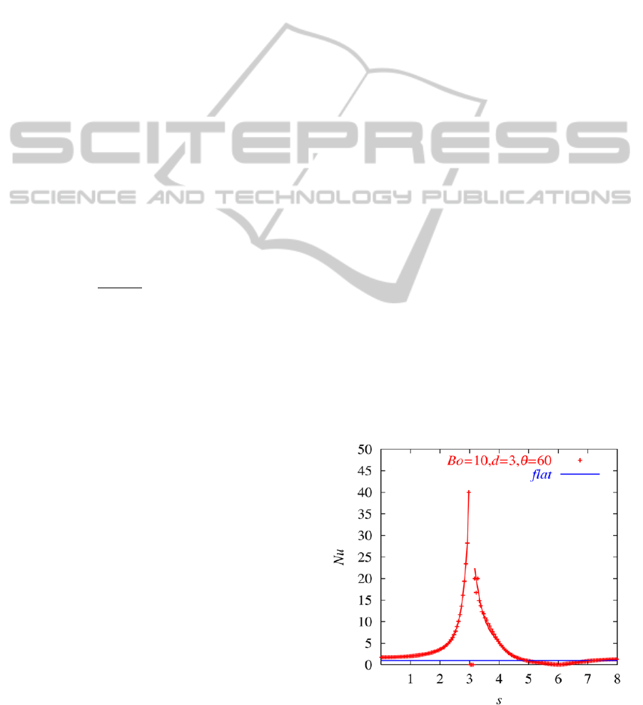
We take the fully developed case of
Bo = 10, d=3
and
=60° shown in Fig.2 (c)
as a typical example of
heat transfer and depict the corresponding local
Nusselt number distribution in Fig.3. As seen in
Fig.2 (c), since the thickness of the liquid film is
decreasing toward the groove edge, the local Nusselt
number in Fig.3 slowly increases along the flat
surface region (s < 3). It has a local maximum at the
groove edge (s~3). On the other hand, the local
Nusselt number suddenly decreases to nearly zero
due to the effect of the break of the film flow(s~3).
After that, it suddenly increases to a local maximum
value and decreases to zero again (3< s < 6). It is
almost zero at the bottom edge of groove (s=6)
because thickness of liquid film flow is too thick to
transport the heat to the wall normal direction. It
slowly increases again along the surface of groove
(6 < s ≤ 8) due to decrease of thickness of liquid film.
Finally we define a mean Nusselt number Nu
m
to
investigate an overall heat transfer performance as
1
.
(23)
If the film distribution is corresponding to the
Nusselt’s solutions along the flat plate, the mean
Nusselt number is as Nu
m
=1. On the other hand, the
mean Nusselt number for the case of Fig.2 (c) is
Nu
m
= 4.071. It is found that the value of Nu
m
is
larger than 1. It should be noted that the increase of
the heat transfer area for d=3, defined as
(w
l
+d+w
b
)/(w
l
+w
b
), is 1.6 compared with the flat
plate. Therefore, the heat transfer performance for
the fluted plate is larger than the increase of the heat
transfer area and that of the flat plate in this case.
In addition, we show the results for the other
values of d and Bond number in Fig.4. This figure
shows the relation between heat transfer, fluted
geometries and surface tension. The mean Nusselt
number is nearly unity for d=1 because the height d
is small and the liquid film covers completely the
fluted part so as to cancel the groove effect. When
the Bond number decreases, the mean Nusselt
number for d=3 slowly increases due to the effect of
decrease of film thickness at the side of groove,
while it decreases for the smaller Bond number. This
is because the break of the film flow proceeds at
groove edge as previously mentioned. On the other
hand, the mean Nusselt number for d=5 gradually
increases even for the smaller Bond numbers, where
any break does not occur yet.
5 CONCLUSIONS
A numerical investigation has been performed for
the two-phase film flow falling down along fluted
plates. Numerical simulations of three-dimensional
flow field have been carried out by using the
HSMAC method, GF method and the CLSVOF
methods based on the finite difference methods for
the plate configuration
3,
2,1,3,5 a
nd
for the non-dimentional parameters 50,
2, and 1, 10, 100.
It is found that the thickness of the film flow
becomes thinner than that of the flat plate because
the film flow falls down into fluted part removing
the film from the top to bottom. However, the break
of the liquid film occurs at the groove edge which
restricts the removal of the film. Heat transfer is
enhanced for the film flow falling down along the
fluted plate, because the liquid film becomes thinner.
Once the break of the film occurs, however, the heat
transfer across the liquid film disappears. So, the
mean Nusselt number decreases for the film flow
with the break even if the averaged film thickness is
thin.
It should be noted that the film flow falling under
the influence of gravity ceases to be laminar and
constant in the stream-wise direction when the flow
rate is increased. Waves tend to appear on the free
surface, and the flow becomes turbulent as the flow
rate is further increased. It is our future work to
investigate such unsteady flow and temperature
fields in the fluted plates.
Figure 3: Local Nusselt number along fluted plate.
HeatTransferEnhancementoftheFilmFlowFallingalongVerticalFlutedPlates
611
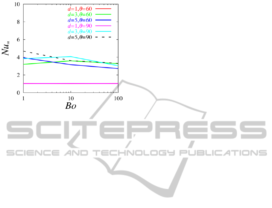
Figure 4: Mean Nusselt number for difference parameters.
ACKNOWLEDGMENTS
The computation in this study has been done using
the facilities of the Supercomputer Centre, the
Institute of Statistical Mathematics (H24-T-25).
REFERENCE
Berlitza, T., Satzgera, P., Summererb, F., Zieglera, F. and
Alefeldb, G. 1999. A contribution to the evaluation of
the economic perspectives of absorption chillers,
International Journal of Refrigeration, Vol. 220,
pp.67-76.
Kapitza, P., L. and Kapitza, S., P., 1965. Wave flow of
thin layers of viscous fluid, Colleted papers of P.L.
Kapitza (Edited by D. T. Haar), Vol. 2, Pergamon
Press, Oxford, pp.662-709.
Krantz, W., B. and Goren, S., L., 1971. Stability of thin
liquid films flowing down a plate, Ind. Eng. Chem.
Fundam., Vol. 10, pp.91-101.
Pierson, F., W. and Whitaker, S., 1977. Some theoretical
and experimental observations of the wave structure
of falling liquid films, Ind. Eng. Chem. Fundam., Vol.
16, pp.401-408.
Gregorig, R., 1954. Hautkondensation an feingewellten
oberflaechen bei beruchsichtigung der
oberflaechenspannungen, Z. Angew. Math. Phys., Vol.
5, pp.36-49.
Kedzierski, M., A. and Webb, R., L., 1990. Practical fin
shapes for surface-tension-drained condensation,
ASME J. Heat Trans., Vol. 112, pp.479-485.
Miyara, A., 2000. Numerical simulation of wavy liquid
film flowing down on a vertical wall and an inclined
wall. Int. J. Therm. Sci., Vol. 39, pp.1015-1027.
Miyara, A., 2001. Flow dynamics and heat transfer of
wavy condensate film. Transactions of the ASME J.
Heat Transf., Vol. 123, pp.492-500.
Al-Sibai F, Leefken, A. and Renz, U., 2002. Local and
instantaneous distribution of heat transfer rates
through wavy films, Int. J. Therm. Sci., Vol. 41,
pp.658-663.
Li, J., Renardy, Y., Y. and Renardy, M., 1998. A
numerical study of periodic disturbance on two-
layer coquette flow, Physics of Fluids, Vol.10,
number 12, pp.3056-3071.
Kang, M., Fedkiw, R., P. and Liu, X-D., 2000. A
boundary condition capturing method for multiphase
incompressible flow, J. Sci. Comput., Vol.15,
pp.323-360.
Gibou, F., Fredkiw, R., P., Cheng, L-T. and Kang, M.,
2002. A second-order-accurate symmetric
discretization of the poisson equation on irregular
domains, Journal of Computational Physics, Vol.176,
pp.205-227.
Son, G. and Dhir, V., K., 2007. A level set method for
analysis of film boiling on an immersed solid surface,
Numerical Heat Transfer, Part B, Vol.52, pp.153-
177.
Wang, Z., Yang, J., Koo., B. and Stern, F., 2009. A
coupled level-set and volume-of-fluid method for
sharp interface simulation of plunging breaking
waves, Int. J. Multiphase flow, Vol.35, pp.227-246.
Adachi, T., 2013. Velocity and temperature profiles
extending over the liquid and gas phases of two-
phase flow falling down vertical plates, Applied
Thermal Engineering, Vol.51, pp.827-832.
SIMULTECH2014-4thInternationalConferenceonSimulationandModelingMethodologies,Technologiesand
Applications
612
