
The Design, Performance and CFD Analyses of Regenerative Blower
used for Fuel Cell System
Chan Lee and Hyun Gwon Kil
Department of Mechanical Engineering, University of Suwon, Hwaseong, Korea
Keywords: Regenerative Blower, Design, Performance, CFD.
Abstract: For efficient design of regenerative blower used for fuel cell system, the design and the performance
analysis methods of regenerative blower are developed, and CFD modelling and simulation are carried out
on the designed blower. The design process of regenerative blower is conducted to determine the geometries
of rotating impellers and stationary side channel with several design variables. The performance analysis on
the designed blower is made by incorporating momentum exchange theory between impellers and side
channel with mean line analysis method, and its pressure loss and leakage flow models are constructed from
related fluid mechanics data and correlations which can be expressed in terms of blower design variables.
The internal flow field of blower is analysed by using the CFX code, a CFD code specialized for fluid
machinery. The present performance analysis method is applied to four existing models for verifying its
prediction accuracy, and the comparison between the prediction and the test results are well-agreed with a
few percentage of relative error. Furthermore, the present design and performance analysis methods are also
applied in developing a new blower used for fuel cell application, and the newly designed blower is
manufactured and tested through chamber-type test facility. The performance prediction by the present
method is well-agreed with the test and the CFD simulation results. Therefore, from the comparison results,
the prediction design and performance analysis methods are shown to be suitable for the actual design
practice of regenerative blower.
1 INTRODUCTION
Regenerative blowers are usually operated with high
pressure rise at low flow capacity, so widely used
for air/ hydrogen supply in fuel cell applications.
However, because regenerative blowers are
operating with low efficiency or a lot of pressure
loss (Badami and Mura, 2012), there are growing
industrial needs for high-efficiency regenerative
blower development. Since the pressure loss is
strongly dependent on the internal flow phenomena
of regenerative blower, for developing high-
efficiency blower, reliable design method with
accurate performance analysis model considering the
flow effects should be developed and applied to
actual design practice of blower industries.
The early theoretical researches on regenerative
blower and pump have been conducted to investigate
the flow pattern and the energy transfer mechanism
of fluid inside the machines, and showed that the
energy transfer to fluid is achieved by the
momentum exchange of the helical-torodal fluid
motion between rotating impeller and fixed side
channel of regenerative machine (Wilson et al.,
1955: Hollenberg and Porter, 1979). Recent
researches by Badami and Mura have been devoted
to improving the performance analysis method of
regenerative blower by using momentum exchange
theory, and the prediction results have been
compared and well-agreed with test and 3-D CFD
results. However, since their analysis model requires
model constants which user should specify, it needs
the generalization of the constants in terms of
blower design and operation parameters (Badami
and Mura, 2011: Badami and Mura, 2012). Lee et al.
proposed an analysis method for regenerative blower
performance by using momentum exchange theory,
and tried to generalize their model constants from
relevant regenerative blower and fluid mechanics
experimental results (Lee et al., 2013).
In the present study, a simple but reliable design-
analysis method of regenerative blower is developed
as in-house program called as the FANDAS-Regen
code. Regenerative blower performance is predicted
751
Lee C. and Gwon Kil H..
The Design, Performance and CFD Analyses of Regenerative Blower used for Fuel Cell System.
DOI: 10.5220/0005104007510755
In Proceedings of the 4th International Conference on Simulation and Modeling Methodologies, Technologies and Applications (SIMULTECH-2014),
pages 751-755
ISBN: 978-989-758-038-3
Copyright
c
2014 SCITEPRESS (Science and Technology Publications, Lda.)

by incorporating mean line analysis method with the
momentum exchange theory between rotating
impeller blades and fixed side channel of blower.
The performance prediction accuracy of the present
method is verified by comparing the prediction with
the measurement results of several actual
regenerative blowers, and the comparison results
show the present method is capable of predicting
blower pressure, efficiency and power very
accurately.
Furthermore, with the use of the present design-
analysis method, a new regenerative blower is
designed, manufactured and tested by using
chamber-type test facility, and its internal flow field
is analyzed by the CFX code, a CFD code
specialized for fluid machinery. The comparison
between the present performance prediction, the
CFD simulation and the test results are well-agreed
within a few percentage of relative error, and they
also show that the present design-analysis method is
very suitable for the actual design practice of
regenerative blower.
2 DESIGN AND ANALYSIS
2.1 Blower Design Method
In general, regenerative blower is composed of
rotating impellers and fixed side channel and its
geometry is shown ( Badami and Mura, 2011) in
Fig.1.
Figure 1: Geometry and design variables of regenerative
blower.
The main design variables of rotating impellers and
fixed side channel are defined as follows:
- Rotation speed (N)
- Tip diameter (D
2
=2r)
- Channel height (h)
- Channel width (W)
- Impeller blade inlet angle (β
1
)
- Impeller blade outlet angle (β
2
)
- No. of impeller blades (Z)
- Impeller blade thickness (d)
- Axial clearance(c)
- Extension angle (θ
c
)
Once the blower design variables are defined, 3-
D blower geometry design can be achieved and then
used for the input data of performance analysis and
CFD simulation.
2.2 Blower Performance Analysis
Models
In the present study, the performance of blower is
analysed by combining the mean line analysis
method for fluid flow and the momentum exchange
theory between impellers and side channel. As
shown in Fig. 2, the gas flow inside regenerative
blower shows typically three dimensional and
helical-toroidal motion where fluid rotates in and
passes along the space between rotating impeller
blades and fixed side channel. The present study
assumes mean streamline as the representative one
of the three dimensional fluid flow phenomena.
(a) Flow behavior inside regenerative blower
(b) Cross section view on helical-toroidal flow
Figure 2: Flow pattern of regenerative blower.
Through the momentum exchange between fluid and
SIMULTECH2014-4thInternationalConferenceonSimulationandModelingMethodologies,Technologiesand
Applications
752
impeller due to this flow motion, gas pressure is
gradually raised along tangential flow path and its
overall pressure rise( ∆p
s
) is calculated by
2
2112
2
1
2(/4)
1
2
sm uu
pf
cc
pQ CC
rr
KK
Aur r u u
u
(1)
where
Here ρ, u, Q
m ,
φ are fluid density, impeller rotation
speed, flow capacity and flow coefficient. More
detailed description and variable definition about
momentum-exchange theory are referred to Badami
and Mura (Badami and Mura, 2012).
Since the fluid flow inside blower results in both
the pressure losses due to fluid friction, turbulence
and mixing and the leakage flow through the axial
clearances between impeller disc and side channel,
the present method needs the pressure loss and the
leakage flow models.
So, in the present study, the pressure loss and the
leakage flow models are constructed by using well-
known fluid mechanics correlations corresponding
to pressure loss and leakage flow sources as shown
in Table 1. It is noted that all the present pressure
losses and the leakage models are expressed as the
functions of blower design variables (Lee et al.,
2013).
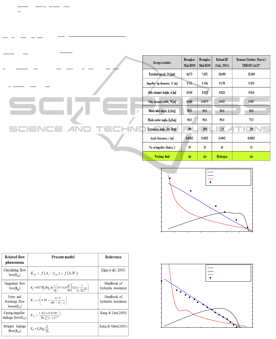
Table 1: Model constants for pressure losses and leakage
flows.
Table 2 summarizes the main design variables of
four actual regenerative blowers used to verify the
present performance prediction accuracy, and all the
blowers are applied in fuel cell applications (Hwang
Hae Elelc., 2012: Badami and Mura, 2011: Gardner
Denver, 2006).
Figs. 3-6 show the performance prediction
results of Mini H-200, Mini H-100, Badami and
Gardner Denver models by the present method,
which are well-agreed with the measurement over
entire flow capacity range.
Table 2: Design variables of four regenerative blowers.
Flow capacity[LPM]
0 50 100 150 200 250 300 350
Efficiency[%], Power[kW]
0
10
20
30
40
50
60
70
80
90
100
110
120
130
140
150
160
Static pressure[mmAq]
0
100
200
300
400
500
600
700
800
900
1000
1100
1200
1300
: Static pressure[ mmAq]-Pred.
: Efficiency [%]-Pred.
: Power[kW]-Pred.
: Static pressure[mmAq]-Exp.
Figure 3: Performance predictions of Mini-H200 model.
Flow capacity[LPM]
0 50 100 150 200 250 300 350
Efficiency[%], Power[kW]
0
10
20
30
40
50
60
70
80
90
100
110
120
130
140
150
160
Static pressure[mmAq]
0
100
200
300
400
500
600
700
800
900
1000
1100
1200
1300
: Static pressure[ mmAq]-Pred.
: Efficiency [%]-Pred.
: Power[kW]-Pred.
: Static pressure[mmAq]-Exp.
Figure 4: Performance predictions of Mini-H100 model.
2
22
222
cot1
uA
Q
A
A
u
u
r
r
u
C
c
mcu
)/22(1.15.1])/(1[
)/22(1.15.1
2
2
21
2
2
2
rrZ
u
u
r
r
u
C
u
11
c
uA
Q
2
1
1
11
22
2
1
2
2
1
2
2
2
cotcot
sin
1
2
1
uA
Q
A
A
u
u
r
r
uA
Q
A
A
A
A
K
c
mcc
c
mc
m
0
2
1
2
1
2
1
2
2
2
2
2
1
u
u
u
u
r
rr
c
c
TheDesign,PerformanceandCFDAnalysesofRegenerativeBlowerusedforFuelCellSystem
753
Flow capacity[LPM]
0 100 200 300 400 500 600 700 800
Efficiency[%], Power[kW]
0
10
20
30
40
50
60
70
80
90
100
110
120
130
140
150
160
Static pressure[mmAq]
0
100
200
300
400
500
600
700
800
900
1000
1100
1200
1300
: Static pressure[mmAq]-Pred.
: Efficiency[%]-Pred.
: Power[kW]-Pred.
: Static pressure[mmAq]-Exp.
: Efficiency[%]-Exp.
Figure 5: Performance predictions of Badami model.
Flow capacity[LPM]
0 50 100 150 200 250 300 350 400 450 500 550 600 650 700
Efficiency[%], Power[kW]
0
10
20
30
40
50
60
70
80
90
100
110
120
Static pressure[kPa]
0
5
10
15
20
25
30
35
40
45
50
55
60
: Static pressure[mmAq]-Pred.
: Ef f iciency[%]-Pred.
: Pow er[kW]-Pred.
: Static pressure[mmA q]-Exp.
Figure 6: Performance predictions of Gardner Denver
model.
2.3 Blower CFD Analysis Method
Based on the blower design of section 2.1, CFD
modelling and simulation are conducted to
investigate the internal flow field of blower. The
present study employs the CFX code, a CFD
program specialized for fluid machinery analysis,
where 3-D RANS (Reynolds-stress Averaged Navier
Stokes equations) solver is used with SST (Shear
Stress Transport) turbulence model. The mesh
generation on rotating impellers and stationary side
channel is made, and the interface between rotating
and stationary flow surfaces is treated by using
frozen rotor scheme (CFX, 2013).
3 APPLICATION RESULTS
The present design and analysis methods are applied
to develop a new regenerative blower used for fuel
cell application. The design requirements and
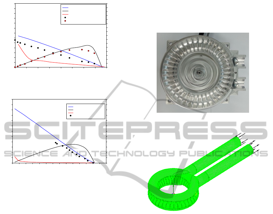
variables of new blower are summarized as follows:
- Rotation speed = 8000 rpm
- Tip diameter( 2r ) = 122 mm
- Side channel height( h ) = 23 mm
- Side channel width( W ) = 9 mm
- No. of impellers( Z ) = 39
Based on the design variables, the new regenerative
blower is manufactured as shown in Fig. 7.
Figure 7: Manufactured model of newly designed blower.
Figure 8: Mesh system of newly designed blower.
Fig. 8 shows the mesh system for the CFD analysis
on the internal flow between rotating impellers and
fixed side channel of newly designed blower. The
CFD computation results on the fluid flow and the
pressure rise through rotating impellers and side
channel are depicted in Fig. 9. As shown in Fig. 9,
the predicted streamline shows the fluid flow
between impellers and side channel is helical-
toroidal motion, and the pressure rise of fluid
passing through tangential flow path is linearly
increased.
Fig. 10 shows the turbulent kinetic energy inside
blower, which is produced due the helical-toroidal
fluid motion between impellers and side channel and
is also linearly increased along tangential flow path.
The performance of newly designed blower
predicted by the present method is compared with
the test results obtained from chamber-type test
facility. As shown in Fig. 11, the predicted pressure
curve is well-agreed with the test except at very low
flow capacity.
SIMULTECH2014-4thInternationalConferenceonSimulationandModelingMethodologies,Technologiesand
Applications
754
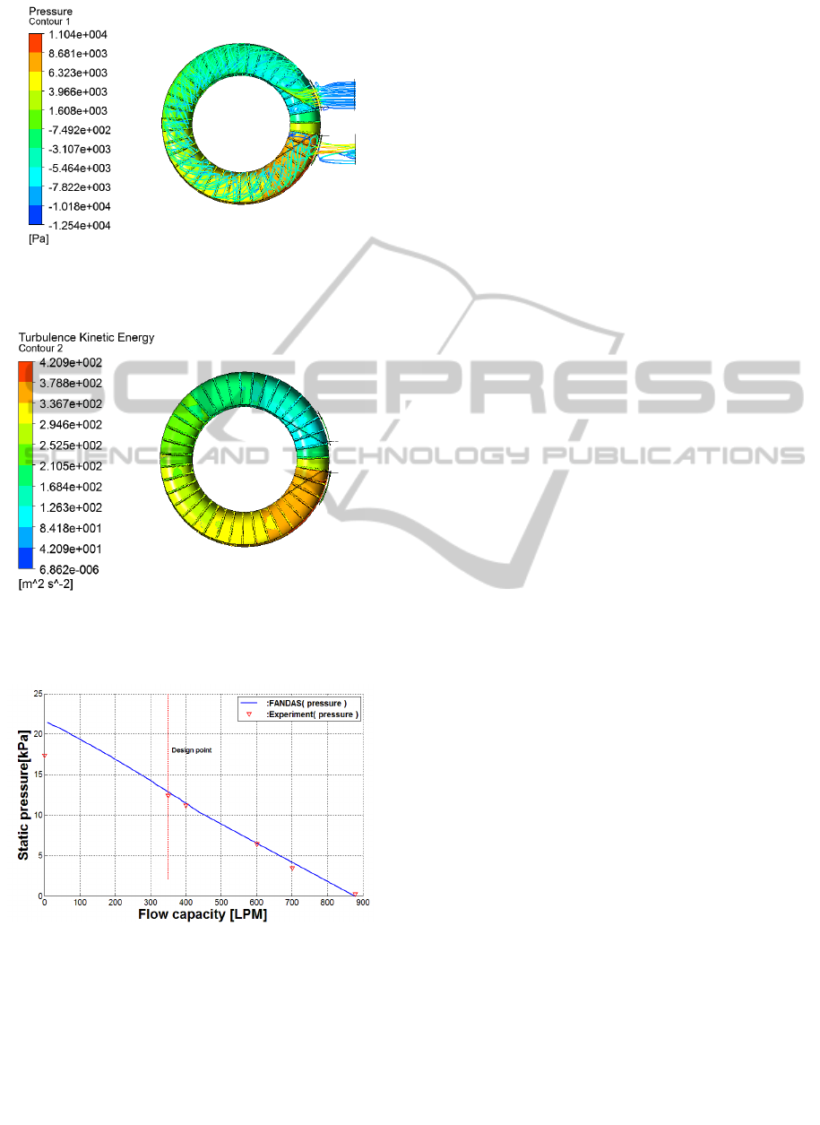
Figure 9: Streamline and static pressure of newly designed
blower.
Figure 10: Turbulent kinetic energy of newly designed
blower.
Figure 11: Pressure curve of newly designed blower.
4 CONCLUSIONS
The present study develops the design-analysis
method which can be applied to the development
process of regenerative blower. The present method
is applied to the performance prediction of four
existing blowers, and is also coupled with CFD
simulation in developing a new regenerative blower
used in fuel cell system. The prediction results by
the present method are well-agreed with the test
results within a few percentage of relative error.
Therefore the present method is expected to be the
reliable design tool suitable in developing
regenerative blower.
ACKNOWLEDGEMENTS
This work was supported by the Development of the
Regenerative Blower for fuel cell application of the
Korea Institute of Energy Technology Evaluation
and Planning (KETEP) grant funded by the Korea
government Ministry of Trade, Industry & Energy,
Republic of Korea.
REFERENCES
W.A. Wilson, M.A. Santalo and J.A. Oelrich, 1955, A
Theory of the Fluid Dynamic Mechanism of
Regenerative Pumps, Trans. ASME, 77, 1303-1316.
J.W. Hollenberg and J.H. Potter, 1979, An Investigation of
Regenerative Blowers and Pumps, Trans. ASME J. of
Eng. For Industry, 110, 147-152.
M. Badami, and M. Mura, 2012, Comparison between 3D
and 1D Simulations of Regenerative Blower for Fuel
Cell Applications, Energy Conversion and
Management, 55, 93-100.
C. Lee, H.G. Kil, G.C. Kim, J.G. Kim, J.H. Ma, and K.H.
Chung, 2013, Aero-acoustic Performance Analysis
Method of Regenerative Blower, J. of Fluid
Machinery( in Korean ), 16(2).
M. Badami and M. Mura, 2011, Setup and Validation of a
Regenerative Compressor Model Applied to Different
Devices, Energy Conversion and Management, 52,
2157-2164.
S.E. Wright, 1976, The Acoustic Spectrum of Axial Flow
Machines, J. of Sound & Vibration 45(2), 165-223.
B.D. Mugridge, 1976, Noise Characteristics of Axial and
Centrifugal Fans as Used in Industry, Shock and
Vibration Digest, 45(3).
M.E. Goldstein, 1976, Aeroacoustics, McGraw-Hill.
Regenerative blower performance and noise test report,
2012, Hwang Hae Electric Co.
Catalogue module1, A Gardner Denver Product, 2006.
ANSYS-CFX user manual, ANSYS Inc., 2013.
TheDesign,PerformanceandCFDAnalysesofRegenerativeBlowerusedforFuelCellSystem
755
