
Laser-based Tracking of People and Vehicles by Multiple Mobile
Robots
Masafumi Hashimoto
1
, Ryunosuke Izumi
2
, Yuto Tamura
2
and Kazuhiko Takahashi
1
1
Faculty of Science and Engineering, Doshisha University, Kyotanabe, Kyoto, Japan
2
Graduate School of Doshisha University, Kyotanabe, Kyoto, Japan
Keywords: Moving-object Tracking, Laser Scanner, Mobile Robot.
Abstract: This paper presents laser-based tracking of moving objects conducted by a group of mobile robots located
near one another. Each robot finds moving objects such as people, cars, and bicycles in its own laser-
scanned images using a binarized occupancy-grid-based method. It then sends laser measurements related to
the detected moving objects to a central server. The central server estimates the pose and size of the moving
objects via the Kalman filter based on received measurements; it then feeds that information back to the
robots. Rule-based and global-nearest-neighbor-based data associations are applied for matching of tracked
objects and laser measurements in multitarget environments. In this cooperative tracking method, the central
server collects the laser measurements from all robots; hence, the robots can always track invisible or
partially invisible objects. The experimental results for two robots in an outdoor environment validate our
tracking method.
1 INTRODUCTION
Tracking (i.e., estimating the motion of) multiple
moving objects is an important issue for the safe
navigation of mobile robots and vehicles. The use of
stereo cameras or laser scanners (LS) in mobile
robotics and vehicle automation has attracted
considerable interest (Arra and Mozos, 2010, Mertz
et al., 2013, Ogawa et al., 2011, Sun et al., 2006).
We have presented a people-tracking method that
uses LS mounted on mobile robots and automobiles
(Hashimoto et al., 2006, Sato et al., 2010). To
introduce robots (such as service and rehabilitation
robots) into human environments, higher accuracy
and reliability of moving-object tracking systems are
required.
Most conventional moving-object tracking
focuses on people under the assumption that a
moving object is a mass point. However, in the real
world, many kinds of moving objects, such as
people, cars, bicycles, and motorcycles, exist.
Therefore, we should treat a moving object as a rigid
body and estimate both pose (position and velocity)
and the object size. Tracking of a rigid body is
known as extended object tracking, and many
studies related to extended object tracking have been
conducted (Fayad and Cherfaoui, 2007, Miyata et
al., 2009, Zhao et al., 2012).
Recently, many studies related to multirobot
coordination and cooperation have also been
conducted. When multiple robots are located near
one another, they can share their sensing data
through intercommunication. Thus, the multirobot
team can be considered a multisensor system.
Therefore, even if moving objects are located
outside the sensing area of a robot, the robot can
recognize them based on tracking data from the
other robots in the team. Hence, multiple robots can
improve the accuracy and reliability of tracking
moving objects (Chou, 2011, Tsokas and
Kyriakopoulos, 2012).
As shown in Fig. 1, in an intelligent transport
system (ITS), if tracking data are shared with
neighboring vehicles, each vehicle can efficiently
recognize moving objects. Therefore, an advanced
driver assist system can be built that detects people
suddenly running on roads and vehicles making
unsafe lane changes in crowded urban environments.
For this purpose, our previous work (Kakinuma
et al., 2012, Ozaki et al., 2012) presented a people-
tracking method using multiple mobile robots. In
this paper, we extend our previous method (people
tracking) to tracking both people and vehicles; their
pose and size are estimated using multiple mobile
522
Hashimoto M., Izumi R., Tamura Y. and Takahashi K..
Laser-based Tracking of People and Vehicles by Multiple Mobile Robots.
DOI: 10.5220/0005084205220527
In Proceedings of the 11th International Conference on Informatics in Control, Automation and Robotics (ICINCO-2014), pages 522-527
ISBN: 978-989-758-040-6
Copyright
c
2014 SCITEPRESS (Science and Technology Publications, Lda.)
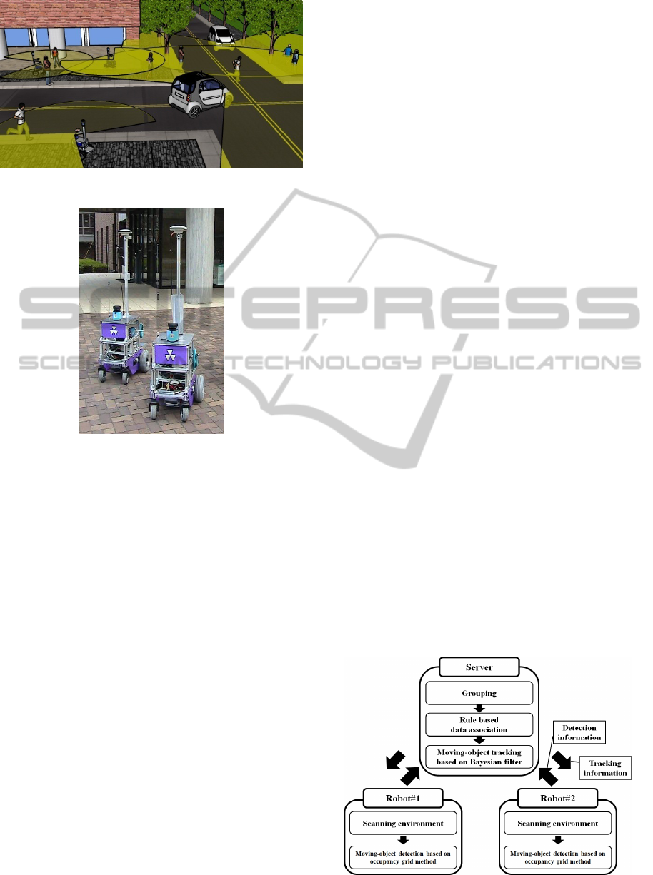
Figure 1: Example of cooperative tracking in ITS.
Figure 2: Overview of the mobile robot system.
robots.
For simplicity, in this paper, moving-object
tracking by multiple mobile robots is referred to as
cooperative tracking, whereas that by an individual
robot in a team is referred to as individual tracking.
The rest of the paper is organized as follows. Section
2 gives an overview of our experimental system. In
Section 3, cooperative tracking is presented. In
Section 4, to validate our method, we describe an
experiment of moving-object tracking by using two
mobile robots in an outdoor environment; we then
present our conclusions.
2 EXPERIMENTAL SYSTEM
Figure 2 shows the mobile robot system used in our
experiments. Each of the two robots has two
independently driven wheels. A wheel encoder is
attached to each drive wheel to measure the wheel’s
velocity. A yaw rate gyro is attached to each robot’s
chassis to sense the turn velocity. These internal
sensors calculate the robot’s pose based on dead
reckoning.
Each robot is equipped with a forward-looking
LS (SICK LMS100). It captures laser-scanned
images that are represented by a sequence of
distance samples in a horizontal plane of 270 deg.
Each robot is also equipped with RTK–GPS
(NovAtel GPS-702-CG). The sampling period of the
sensors is 10 Hz. The angular resolution of the LS is
0.5 deg, and each scan image consists of 541
distance samples. We use broadcast communication
by wireless LAN to exchange information between
the central server and the robots.
3 MOVING-OBJECT TRACKING
3.1 Overview
As shown in Fig. 3, each robot independently finds
moving objects in its own laser image based on a
binarized occupancy-grid method (Hashimoto et al.,
2006). The robot uploads laser measurements related
to moving objects to a central server.
Laser measurements (positions) from the same
moving object have similar values, whereas those
from different objects are significantly different.
Thus, the central server clusters laser measurements
by checking the gap between two adjacent
measurements. Subsequently, the server tracks
moving objects (estimates their size, position, and
velocity) and transmits the tracking data to the
robots.
The grid map is represented on a world
coordinate frame. To map the laser-scanned images
onto the coordinate frame, each robot needs to
identify its own pose with a high degree of accuracy
on the world coordinate frame. To define the world
coordinate frame, we consider the GPS base station
as the origin. Each robot determines its own pose
based on dead reckoning and GPS information via
the extended Kalman filter.
Figure 3: System overview of cooperative tracking.
Laser-basedTrackingofPeopleandVehiclesbyMultipleMobileRobots
523
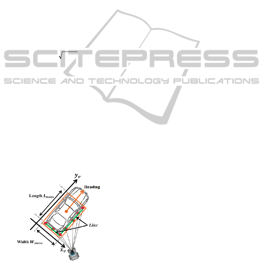
3.2 Size and Pose Estimation
We assume that the shape of the moving object is
represented by a rectangle with width W and length
L. As shown in Fig. 4, we define an x
v
y
v
-coordinate
frame on which the y
v
-axis aligns with the heading
direction of a tracked object. From clustered laser
measurements related to a moving object (hereafter,
moving-object measurements), we extract the width
W
meas
and length L
meas
. The size of the tracked object
is then estimated by the following equation (Fayad
and Cherfaoui, 2007):
)(
)(
11
11
kmeaskk
kmeaskk
LLGLL
WWGWW
(1)
where W and L are estimates of width and length,
respectively, k and k
1 are time steps. G is the filter
gain, given by
k
pG )1(1
, and p is a
parameter; the larger the value of p, the more
reliable the current measurements, W
meas
and L
meas
.
To extract W
meas
and L
meas
from the moving-object
measurements, we need to obtain the heading
direction of the tracked object; as shown in Fig. 4,
we extract two lines based on the split and merge
method (Nguyen et al., 2009) from the moving-
object measurements and determine the heading
direction of the tracked object from the orientation
of the lines. When we cannot extract the two lines,
we determine the heading direction of the tracked
object from the velocity estimate of the object,
which is estimated by the following method.
We define the centroid position of the rectangle
estimated by Eq. (1). From the centroid position, the
pose of the tracked object (position and velocity,
Figure 4: Size estimate. Red circles indicate moving-
object measurements. Green lines indicate extracted lines
based on these measurements. Orange rectangle indicates
the estimate rectangle, and orange circle indicates the
centroid of the rectangle.
estimated by the Kalman filter under the assumption
that the object moves at a nearly constant velocity.
Objects appear in and disappear from the sensing
area of the LS. They also interact with and are
occluded by each other and other objects in the
environment. To maintain the reliable tracking under
such conditions, we implement a rule-based
tracking-management system (Hashimoto et al.,
2006).
3.3 Data Association
To track objects in multi-object and multi-
measurement environments, we need data
association (one-to-one matching of tracked objects
and laser measurements); a validation region is set
around the predicted position of each tracked object.
The shape of the validation region is rectangular,
and its length and width are 0.8 m longer than those
for the object estimated at the previous time step.
We refer to the representative of grouped
moving-object measurements as the representative
measurement. Representative measurements inside
the validation region are considered to originate
from the tracked object and are used to update the
position of the tracked object using the Kalman filter,
whereas those outside the validation region are
identified as false alarms and discarded.
As shown in Figs. 5 and 6, in the real world,
multiple representative measurements often exist
inside a validation region; multiple tracked objects
also compete for representative measurements. To
achieve a reliable data association (matching of
tracked objects and representative measurements),
we introduce the following rules:
a) Person: Because person sizes are small, a
person usually results in one representative
measurement. Thus, if a tracked object is considered
a person, matching of a tracked person and a
representative measurement (one-to-one matching)
is performed.
b) Vehicle: Because vehicle sizes are large, as
shown in Fig. 5, a vehicle often results in multiple
representative measurements. Thus, if a tracked
object is considered a vehicle, matching of a tracked
vehicle and representative measurements (one-to-
many matching) is performed.
Based on the estimated size of the tracked object,
we decide whether the object is a person or a
vehicle; if the estimated size in length or width is
larger than 0.8 m, the object is determined to be a
vehicle; otherwise, a person.
On urban streets, people often move near
vehicles, whereas vehicles move far away from each
ICINCO2014-11thInternationalConferenceonInformaticsinControl,AutomationandRobotics
524
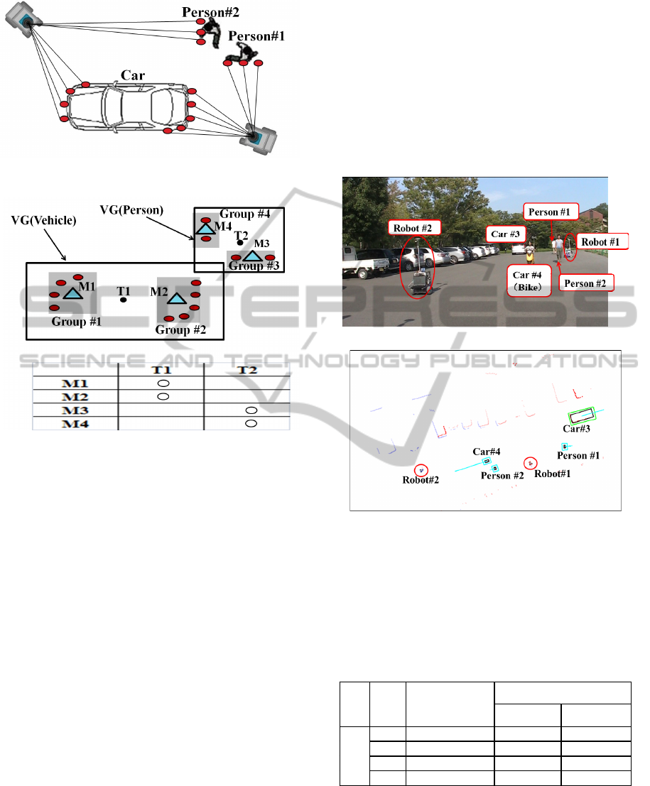
Figure 5: Laser measurements obtained using two robots.
Figure 6: Data association. Black and red circles indicate
tracked objects and moving-object measurements,
respectively. Light blue triangles indicate representative
measurements for moving-object measurements. VG stands
for validation region.
other. Thus, when representative measurements of
people exist in the validation region of a tracked
vehicle, they might be matched to the tracked
vehicle. To avoid that situation, we begin data
association with people.
As shown in Fig. 6, if a tracked object T2 is
determined to be a person, the representative
measurement M3 is matched with T2 based on the
global nearest neighbor (GNN) method
(Konstantinova et al, 2003). Next, if a tracked object
T1 is determined to be a vehicle, the two
representative measurements M1 and M2 are
matched with T1. The representative measurement
M4 that is not matched with any tracked objects is
considered either to originate from a new object or
to be a false alarm. Therefore, we tentatively initiate
tracking of the measurement with the Kalman filter.
If the measurement is always visible, it is considered
to originate from a new object and tracking is
continued. If the measurement soon disappears, it is
considered to be a false alarm and tentative tracking
is terminated.
4 EXPERIMENTAL RESULTS
We evaluated our tracking method by conducting an
experiment in an outdoor environment, shown in
Fig. 7(a). Two robots that are moving around track
two people, a car, and a motorcycle; Fig. 8 shows
their movement paths. The moving speed of the
robots, people, car, and motorcycle were about 3
km/h, 5 km/h, 15 km/h, and 20 km/h, respectively.
Experimental time was 27 s (270 scans).
(a) Photo of the experimental environment.
(b) Tracking result.
Figure 7: Moving-object tracking experiment. In (b), black
rectangles indicate the estimated size of moving objects.
Green and blue rectangles indicate the validation regions
of cars and people, respectively. Blue bars indicate the
estimated the moving direction. Red and blue points
indicate laser images taken by robots #1 and #2,
respectively.
Table 1: Tracking duration.
Cooperative
tracking
Individual tracking by
Robot #1 Robot #2
Moving
object
#1 64–177[scan] 64–177 None
#2 65–270 65–270 188–243
#3 89
–
183 89
–
183 96
–
136
#4 127–182 127–181 169–182
Laser-basedTrackingofPeopleandVehiclesbyMultipleMobileRobots
525
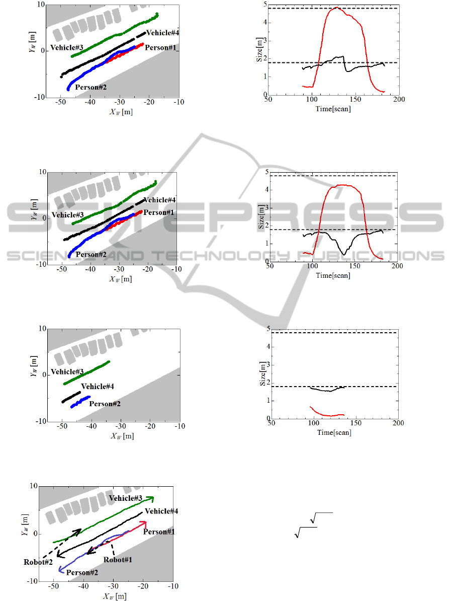
(a) Estimated track (pose) of moving objects. (b) Estimated size of vehicle #3.
Figure 9: Pose and size estimated by the cooperative tracking of two robots. In (b), red and black lines indicate the
estimated length and width, respectively, of vehicle #3; two dashed lines indicate the true length and width of vehicle #3.
(a) Estimated track (pose) of moving objects. (b) Estimated size of vehicle #3.
Figure 10: Pose and size estimated by the individual tracking of robot #1.
(a) Estimated track (pose) of moving objects. (b) Estimated size of vehicle #3.
Figure 11: Pose and size estimated by the individual tracking of robot #2.
Figure 8: Movement path of moving objects.
In this experiment, the filter gain G from Eq. (1) is
determined as follows:
scan 10for369.001.01
scan 10for01.01
10
k
k
G
k
Figure 7(b) shows the tracking results at 16 s
(160 scans). Figure 9 shows the tracking of people
and vehicles as well as the size of vehicle #3, as
estimated by two robots (cooperative tracking). For
comparison, individual tracking by each robot was
also conducted. The tracking results for robots #1
ICINCO2014-11thInternationalConferenceonInformaticsinControl,AutomationandRobotics
526

and #2 are shown in Figs. 10 and 11, respectively.
Table 1 shows the tracking duration.
These results show that cooperative tracking
using two robots can provide better tracking
accuracy than individual tracking using either robot
#1 or #2.
5 CONCLUSIONS
This paper presented a laser-based method for
tracking of moving objects (people and vehicles)
that uses multiple mobile robots located near one
another. The size and pose (position and velocity) of
the objects were estimated, and the method was
validated by an experiment of people and vehicle
tracking using two robots.
In our method, robots find moving objects in
their sensing area and transmit object information to
a central server, which then estimates the size and
pose for each moving object. Such a server-client
system is weak from the view-point of system
dependability and computational burden. Future
research will be directed to the design of a
decentralized architecture in moving-object tracking.
ACKNOWLEDGEMENTS
This study was partially supported by Scientific
Grants #23560305 and #26420213, Japan Society
for the Promotion of Science (JSPS).
REFERENCES
Arra, K. O., and Mozos, O. M., 2010. Special issue on:
People Detection and Tracking, In International
Journal of Social Robotics, Vol.2, No.1.
Chou, C. T., Li, J. Y., Chang, M. F., and Fu, L. C., 2011.
Multi-Robot Cooperation Based Human Tracking
System Using Laser Range Finder, In Proceeding of
IEEE International Conference on Robotics and
Automation (ICRA2011), pp. 532–537.
Fayad, F., and Cherfaoui, V., 2007. Tracking Objects
Using a Laser Scanner in Driving Situation based on
Modeling Target Shape, In Proceeding of the 2007
IEEE Intelligent Vehicles Symposium (IV2007),
pp.44–49.
Hashimoto, M., Ogata, S., Oba, F., and Murayama, T.,
2006. A Laser Based Multi-Target Tracking for
Mobile Robot, In Intelligent Autonomous Systems 9,
pp.135–144.
Kakinuma, K., Hashimoto, M., and Takahashi, K., 2012.
Outdoor Pedestrian Tracking by Multiple Mobile
Robots Based on SLAM and GPS Fusion, In
Proceeding of IEEE/SICE International Symposium on
System Integration (SII2012), pp. 422–427.
Konstantinova, P., Udvarev, A., and Semerdjiev, T., 2003.
A Study of a Target Tracking Algorithm Using Global
Nearest Neighbor Approach, In Proceeding of
International Conference on Systems and
Technologies.
Mertz, C., Navarro-Serment, L. E., et al., 2013. Moving
Object Detection with Laser Scanners, In Journal of
Field Robotics, Vol.30, No.1, pp.17–43.
Miyata, T., Ohama, Y., and Ninomiya, Y., 2009. Ego-
Motion Estimation and Moving Object Tracking using
Multi-layer LIDAR, In Proc. of IEEE Intelligent
Vehicles Symposium (IV2009), pp.151–156.
Nguyen, V., Martinelli, A., Tomatis, N., and
Siegwart, R., 2009. A comparison of Line Extraction
Algorithms using 2D Laser Rangefinder for Indoor
Mobile Robotics, In Proceeding of 2005 IEEE/RSJ
International Conference on Intelligent Robots and
Systems (IROS2009), pp.1929–1934.
Ogawa, T., Sakai, H., Suzuki, Y., Takagi, K., and
Morikawa, K., 2011. Pedestrian Detection and
Tracking using in-vehicle Lidar for Automotive
Application, In Proceeding of IEEE Intelligent
Vehicles Symposium (IV2011), pp. 734–739.
Ozaki, M., Kakinuma, K., Hashimoto, M., and Takahashi,
K., 2012. Laser-Based Pedestrian Tracking in Outdoor
Environments by Multiple Mobile Robots, In Sensors,
Vol. 12, pp. 14489–14507.
Sato, S., Hashimoto, M., Takita, M., Takagi, K., and
Ogawa, T., 2010. Multilayer Lidar-Based Pedestrian
Tracking in Urban Environments, In Proceeding of
IEEE Intelligent Vehicles Symposium (IV2010), pp.
849–854.
Sun, Z., Bebis, G., and Miller, R., 2006. On-Road Vehicle
Detection: A Review, In IEEE Transaction on Pattern
Analysis and Machine Intelligence, Vol. 28, No. 5, pp.
694–711.
Tsokas, N. A., and Kyriakopoulos, K. J., 2012. Multi-
Robot Multiple Hypothesis Tracking for Pedestrian
Tracking, In Autonomous Robot, Vol. 32, pp. 63–79.
Zhao, H., Sha, J., Zhao, Y., Xi, J., Cui, J., Zha, H., and
Shibasaki, R., 2012. Detection and Tracking of
Moving Objects at Intersections Using a Network of
Laser Scanners, In IEEE Transaction on Intelligent
Transportation Systems
, Vol.13, No.2, pp.655–670.
Laser-basedTrackingofPeopleandVehiclesbyMultipleMobileRobots
527
