
An Ontology based Approach for Assisting Conceptualisation in CAD
Processes
Ewa Grabska
Faculty of Physics, Astronomy and Applied Computer Science, Jagiellonian University, 4 Reymont Str., Krakow, Poland
Keywords: Visual Design, Design Requirement, Diagram, Design Knowledge, Many-Sorted First-Order Logic.
Abstract: This paper continues development of ontological approach to conceptual visual design aided by computer.
Design ideas during the conceptualization phase are externalized by the designer in the form of diagrams on
the monitor screen and automatically transformed by the system into data structures being hyper-graphs.
Hyper-graph structures are combined with logic-based knowledge representation techniques. Different types
(sorts) are used to represent knowledge from diagrams and many-sorted first order languages for their for-
mal specification. The paper is the next attempt to formalize ontology-based knowledge framework for
CAD process. The proposed method is illustrated with an exemplary of design of floor-layouts aided by the
prototype of the System, so called HSSDR (Hyper-graph System Supporting Design and Reasoning).
1 INTRODUCTION
Computer Aided Design (CAD) belongs to well-
established research areas. There are many computa-
tional tools for describing, editing, analyzing, and
evaluating design projects, but the initial conceptual
design phase, mainly based on ontological
knowledge, is very rarely supported by computer
(Yurchyshyna and Zarli, 2009). The application of
ontology in CAD is relatively new and problem ori-
ented.
This paper deals with an ontology based ap-
proach to the conceptual stage of the design process
supported by CAD-system. Different types of design
knowledge essential in visual aspects of a human-
computer dialogue are considered. Initial stages of
designer’s conceptualization are often associated
with sketching. In the proposed approach sketches
are replaced by design drawings in the form of dia-
grams created by the designer on the monitor screen
with the use of a visual editor. The initial drawings
constitute the first type of representation storing in-
formation about design solutions. The conceptual
stage of design is based on this representation, which
is important for visual assessment of drawings by
the designer, however not comprehensible for the
computer. Supporting the conceptual design phase
by the computer system requires the data structure
representing the drawings. In the presented approach
they are automatically transformed into attributed
hyper-graph structures. Machine information pro-
cessing in the considered system is based on the
proposed graph representation of design drawings,
which is used by the system to store design
knowledge about drawings and reason about them.
The design knowledge stored in the proposed type of
a graph is translated into logic formulas describing
diagrams. The presented reasoning mechanism
based on these formulas enables the system to check
whether designs satisfy specified requirements and
constraints. The proposed system makes it possible
not only to extract design knowledge from externali-
zations of designer’s conceptualization but also to
support intelligent decision-making throughout the
conceptual design process.
The presented approach continues development
of knowledge-based decision support design system
(Grabska and Ślusarczyk, 2011). The prototype im-
plementation of this system called the HSSDR (Hy-
per-graph System Supporting Design and Reason-
ing) has been considered in (Grabska et al, 2009).
This paper extends ontological aspects related to
conceptual visual design aided by computer present-
ed in (Grabska, 2011) and simplifies the proposed
earlier top-level ontology for the study of visual
conceptual design process. Our research will be fo-
cused on ontological commitments between design-
er’s conceptualization and different types of
knowledge representation which will be used during
conceptual design process supported by CAD-
272
Grabska E..
An Ontology based Approach for Assisting Conceptualisation in CAD Processes.
DOI: 10.5220/0005080902720279
In Proceedings of the International Conference on Knowledge Engineering and Ontology Development (KEOD-2014), pages 272-279
ISBN: 978-989-758-049-9
Copyright
c
2014 SCITEPRESS (Science and Technology Publications, Lda.)

system. Both computer-aided problem solving and
knowledge representation of visual design use struc-
tures of different types (sorts) and many-sorted first
order languages for their formal specification. The
considered in (Grabska, 2011) standard first-order
languages is replaced by more flexible logic lan-
guages in which the concept of sort will be used.
The proposed ontology based approach for as-
sisting conceptualization in CAD process will be
illustrated with an exemplary of design of floor-
layouts supported by system HSSDR.
2 RELATED WORK
Although detailed design and documentation phases
are usually well aided in CAD tools, the initial con-
ceptual design phase is the least supported by the
computer (Minas, 2002). The appropriate computer
representation of knowledge and methods for
knowledge manipulation are needed to construct
knowledge-based design systems (Coyne et al.
1990). These systems are expected to extend their
functionality far over merely creating and editing of
design drawings by the user on the monitor screen.
Following the BIM paradigm (Eastman et al. 2008)
they store all project 3D elements in a central data-
base and are able to generate 2D drawings and 3D
renderings. However, most of these tools do not use
data structures to reflect the design knowledge ex-
tracted from initial drawings created by the designer
on the monitor screen during the conceptual design
phase. This knowledge provides a starting point for
design refinement. Therefore, knowledge-based de-
sign systems must be integrated with CAD tools, in
particular with their graphic editors, to facilitate de-
sign process. In other words, we really need to know
much more about how to get computers to have in-
telligent design conversation with us (Lawson,
2001).
The conceptual design phase needs a new ap-
proach based on ontology for assisting designer’s
conceptualization during CAD processes. The pro-
posed in this paper approach provides the automatic
way of generating graph data structure representing
drawings created by the designer on the screen.
These structures have the form of attributed hyper-
graphs which are used quite frequently in
knowledge-based design tools (Schurr et al. 1995) to
facilitate reasoning with logic formulas. The lan-
guage of logic that is the widely used in the theory
of knowledge representation is the language of first-
order formulas (Fagin et al. 1995).
In this paper many-sorted first order languages cor-
respond to attributed hypergraphs. In the languages
arguments and values of functions, and arguments of
predicates may have different sorts (Lifshitz and
Morgenstern, 2008). The many sorted first order
logics are used to semantics and program verifica-
tions, definition of programming languages, data-
bases, computer aided problem solving, and logic
programming and automated deduction.
During the design process aided by computers
drawings being externalization of designer’s concep-
tualisation are seen as thinking aids (Suwa and
Tversky, 1997). The importance of visualization in
design was discussed in (Visser, 2006), while dia-
grammatic conventions allowing for common com-
munication were described in (Booch, et al. 2005).
Another model of inventive designing based on vis-
ual thinking was presented in (Arciszewski, et al.
2009). Visualizing of conceptualizations in the form
of diagrams which facilitate linking mental trans-
formations with physical ones is presented in
(Tversky, 2001). Finding meaning in the reinterpre-
tation of visual representations is discussed in
(Tversky and Suwa, 2009). This paper analyzes the
role of visualization in the process of conceptual
design in the framework of computational ontology.
3 FORMAL MODEL
During the conceptual visual design process aided
by computer the designer has a kind of conversation
with visual objects. This dialogue can be character-
ized as the following cycle: drawing visual objects,
inspecting them, finding new things (e.g., emergent
shapes and/or relations, feedback from the computer
system), and redrawing (Goldschmidt, 1994).
To describe this dialogue the following key
concepts are distinguished (Guarino et al, 2009):
the domain of discourse being a subset of our
cognitive domain,
conceptualization, i.e., the objects, concepts,
and other entities that are assumed to exist in
the considered domain of discourse and the re-
lationships that hold among them,
knowledge based computer system represent-
ing the conceptualization and a logic language
for its explicit specification, and
with respect to the system observable states of
world which constitute designer’s world.
In the presented approach visual design aided by
computer is our cognitive domain, while designing
floor-layout makes the domain of discourse. In con-
ceptual design process understanding of require-
AnOntologybasedApproachforAssistingConceptualisationinCADProcesses
273

ments based on conceptualizations created in de-
signer’s mind goes together with the visualization of
early design solution (Grabska, 2010). The design-
er’s conversation with visual objects focus on dy-
namic character of the context in which designing
takes place.
It is worth noting that in visual design aided by
computer we need to explicitly specify conceptual-
ization, while conceptualizations are typically im-
plicit in the mind of designer.
Formally, we start with the definition of concep-
tualization stated by Genesereth and Nilsson (Gene-
sereth and Nilsson, 1987).
Definition 1
A conceptualization is a tuple
C = (U, R) where
U is a set called the domain of discourse, and
R is a set of relations on U.
In practical application we need to use a language to
refer to the elements of a conceptualization. The
designer usually begins with doing sketches. In other
words he/she uses a visual language. The designer
on the base of the conceptualization can generate an
observable world state. Recently conceptual process
in his/her mind is supported by cognitive tools, such
as computer screen (Tversky and Suwa, 2010). In
this paper to represent the world state, the concept of
visual site will be used (Shimojima, 1996).
A visual site is a drawing along with a surface
on which it is drawn. In general
different surfaces
can be used for drawing, e.g., a sheet of paper or a
monitor screen. Two different drawings on the same
surface determine two different visual sites. In visual
design aided by computer, monitor screen is a basic
visual site on which besides drawing some infor-
mation from computer system can be generated
(Grabska, 2012).
A world is defined as an ordered set of world
states. During the conceptual design phase the world
in the form of a sequence of visual sites is generated
by the designer. In each step of design process for
the same domain of discourse the designer changing
number of elements of the domain of discourse U
and/or relations on it can devise a new conceptual-
ization.
Example 1
Designer’s diagrams presented in the running exam-
ple are made with the use of the prototype system
HSSDR (Grabska et al, 2009). Let us consider the
specialized CAD editor of the HSSDR interface for
designing floor layout composed of polygons which
are placed in an orthogonal grid. These polygons
represent functional areas or rooms. On the base of
ontology the designer visualizes an initial diagram
with three component shown in Figure 1. According
to designer’s convention each line shared by poly-
gons in the diagram is associated with one of two
relations. Lines with door symbol on them represent
the accessibility relation among components, while
continuous lines shared by polygons denote the ad-
jacency relation between them. In our approach the
monitor screen with the diagram shown in Fig. 1
represents the first observable world state w
1
.
Figure 1: The diagram corresponding to the conceptualiza-
tion for w
1
.
Let C be a conceptualization and W be the set of
world states for C. The tuple (U, W) is called a do-
main space for C. The space fixes variability of the
domain of discourse U with respect to the possible
world states of W.
Definition 2
A conceptual relation
n
of arity n defined on a
domain space (U, W) is a function
n
: W → (U
n
) from the set W into the set of all
n-ary relations on U.
The conceptual relation allows one to extend the
notion of conceptualization for all observable world
states (Guarino et al, 2009).
Definition 3
A conceptualization for W is a triple
C = (U, W,
),
where
U is a domain of discourse,
W is a set of world states, and
is a set of conceptual relations
n
on the
domain space (U, W).
Example 2
In the next step of design the designer on the base of
the conceptualization for world state w
1
divides the
area labelled by S into two rooms labelled by Ba and
KEOD2014-InternationalConferenceonKnowledgeEngineeringandOntologyDevelopment
274
Be. The monitor screen with the diagram shown in
Figure 2 represents the
conceptualization for world
state w
2
.
In the presented approach to visual design, draw-
ings of the visual sites from W are the main source
of knowledge about created designs. Mutual location
of polygons is determined by the designer. The sides
of each polygon are ordered clock-wise starting from
the top left-most one. In a diagram only qualitative
coordinates are used, i.e., only relations among
graphical elements (walls) are essential.
Figure 2: The drawing corresponding to the conceptualiza-
tion for w
2
.
Drawings are automatically transformed by
HSSDR system into appropriate data graph struc-
tures. Hyper-graphs are used for modelling and
modification of knowledge about drawings
(Grabska, 2011). They can be treated as an extension
of conceptual graphs (Sowa, 1984) with appropriate
structures for local graph transformations. The pro-
posed hyper-graphs have two types of hyper-edges,
called object hyper-edges and relational hyper-
edges. Hyper-edges of the first type correspond to
drawing components and they are labelled by com-
ponent names. Hyper-edges of the second type rep-
resent relations among fragments of components and
can be either directed or non-directed in the case of
symmetric relations. Relational hyper-edges of the
hyper-graph are labelled by names of relations. Ob-
ject hyper-edges are connected with relational hy-
per-edges by means of nodes corresponding to
common fragments of connected drawing compo-
nents.
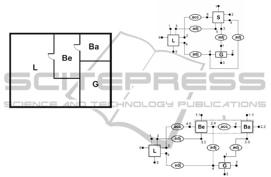
Example 3
The hyper-graph corresponding to the drawing pre-
sented in Figure 1 is shown in Figure 3. When de-
signing the drawing the designer specifies labels of
components related to room types. For each labelled
design component in the form of a polygon one
component hyper-edge is created. The hyper-graph
shown in Fig. 3 consists of 8 hyper-edges. It has 3
object hyper-edges corresponding to the three poly-
gons being components of the layout and 5 relational
hyper-edges. The relational hyper-edges labelled by
acc (representing accessibility relation) is only one
among relational hyper-edges. The remaining four
relational hyper-edges with label adj represent adja-
cency relation.
Figure 3: The hyper-graph for the diagram in Fig. 1.
The hyper-graph for the drawing corresponding to
the conceptualization for w
2
is presented in Fig. 4.
Figure 4: The hyper-graph for the diagram in Fig. 2.
As we can see the conceptualization for w
2
differs
from the conceptualizations for w
1
both in the num-
bers of components and elements of accessible rela-
tion.
Elements of the domain of discourse have attrib-
utes, like length, area, orientation, colour, etc. In
HSSDR system attributes corresponding to compo-
nents of the drawing are assigned by means of the
attribute function to nodes and object hyper-edges.
Sets of values for particular attributes can be differ-
ent. For instance, values of the area and length are
real numbers, while
values of the orientation belong
to the set {South, West, North, East} of directions.
Let Σ be a fixed alphabet of labels of hyper-edges
and nodes and let A be a set of attributes of hyper
edges and nodes.
Definition 4
An attributed hypergraph over Σ and A is a system
H = (E, V, t, s, lb, att), where
AnOntologybasedApproachforAssistingConceptualisationinCADProcesses
275

E = E
O
∪
E
R
is a nonempty finite set of hy-
peredges, where elements of E
O
, called object
hyperedges, represent drawing components,
while elements of E
R
, called relational hy-
peredges, represent relations,
V is a nonempty finite set of nodes,
t: E → V* is a mapping assigning sequences
of different target nodes to all hyper-edges,
s: E
R
→ V* is a mapping assigning sequences
of different source nodes to relational hyper-
edges,
lb: E
∪
V → Σ is a labelling function, such that
lb(E)∩lb(V ) =
Ø
and
lb(E
O
)∩lb(E
R
) =
Ø
,
att: E
O
∪
V → 2
A
is an attributing function,
where 2
A
is a set of all subsets of A.
Denote by H(Σ, A) the set of all atoms of attributed
hypergraphs over Σ and A, i.e., the set of all hyper-
edges and nodes.
During the conceptualization in CAD-process
semantic and syntactic information about a drawing
created by the designer is encoded in the hyper-
graph and then translated to first-order logic
formulas forming knowledge about design solutions.
Logic formulas are built over a vocabulary T = {S,
F, P} composed of set S of sort symbols, set F of
function symbols and set P of predicate symbols.
With respect to the considered CAD-system two
types of sorts are distinguished. The former
corresponds to objects of domain of discourse and
the latter – the values of attribute functions defined
on the objects.
Let C = (U,W,
) be a conceptualization for W,
and D = D
a
a
A
be indexed family of ranges of
values of attribute functions defined on U.
Definition 5
A many sorted vocabulary of the first order logic is
a triple
T = (S, F, P), where
S = {U, D } is a set of sort symbols,
F is a set of elements f such that f is n-ary
function symbol for n > 0 such that
f: s
1
×s
2
×…×s
n
→ s, where s
i
, s
∊
S, i = 1,…,n,
and f is a constant symbol for n = 0,
P is a set of m-ary predicate symbols p with
arguments s
1
×s
2
×…×s
m
, s
i
∊
S, i = 1,…,m.
Let us define the ontological commitment
between the vocabulary of T and a conceptualization
C for W.
Definition 6
Let C = (U,W,
) be a conceptualization for W and
T = (S,F,P) be a many sorted alphabet of the first
order logic.
An ontological commitment between T and C is
a partial function α: T → C satisfying the following
conditions:
objects of U with respect to the possible world
states of W are assigned to sort symbols,
objects of D are assigned to constant symbols,
and
predicate with arguments of U are assigned to
predicate symbols.
Example 4
Let us come back to design floor-layouts shown in
Fig. 1 and Fig. 2 and consider the ontological
commitment between vocabulary and designer’s
conceptualization with respect to the possible world
states of W, i.e., represented by visual sites along
with designs drawings. Shapes which represent
rooms, walls and doors correspond to elements of
the objects of U, whereas the set of real numbers
and the set of directions, i.e.,{South, West, North,
East} – to values of D. Function symbols such as
area and length, and directions with arguments of U
as well as the ranges of values being the set of
and the set {South, West, North, East} correspond to
attributes of objects. Predicate symbols such as acc
and adj determine relations between rooms.
Since HSSDR system deals with computer
representation of drawings, the explicit specification
must be formal, i.e., the expressions must be
computer readable. We assume that our language is
a many sorted first-order logical language. The
semantics of many-sorted first-order formulas uses
relational structures based on knowledge encoded in
the considered hyper-graphs. A relational structure
consists of domains of different types (sorts) and a
way of associating with each of elements of the
vocabulary T corresponding entities over the domain
(Ślusarczyk, 2011)
Definition 7
A relational T-structure L consists of:
a domain dom(L) = dom(L
U
)
dom(L
D
), where
dom(L
U
) and dom(L
D
) contain domains for
objects of domain of discourse U and for
attribute values of D, respectively,
an assignment c
L
dom(L
U
) to each constant
symbol c of U,
an assignment c
L
dom(L
D
) to each constant
symbol c of D,
KEOD2014-InternationalConferenceonKnowledgeEngineeringandOntologyDevelopment
276
an assignment n-ary function
f
L
: dom(L)
n
domL
to each n-ary function
symbols f
F, and
anassignment
n‐ary
predicate
p
L
dom(L)
n
toeach
n–ary
predicate symbol p
P.
In the proposed visual design approach the
T-relational structure L contains two domains:
dom(L
U
)
H
(Σ, A) is a set of component hy-
per-edges E
O
and a set of hyper-graph nodes
V, and
dom(L
D
) is an indexed family of sets
D =
D
a
a
∊
A
, where
A is a set of attribute functions defined on
E
O
and V and for each a
∊
A, D
a
is the range
of attribute values of function a in D.
Relations between design components presented in
the drawing are specified between fragments of
these components, which correspond to hyper-graph
nodes. The interpretation of each relation is the hy-
per-edge relation of the hyper-graph such that there
is a relational hyper-edge coming from a sequence
of nodes of at least one component hyper-edge and
coming into a sequence of nodes of other component
hyper-edges. Functions determine attribute values
for components hyper-edges and nodes.
The next step to define the formal semantics of
formulas is a specification of an interpretation of
variables. A valuation on a structure L is a function
from variables to elements of dom(L). Given a rela-
tional structure L with a valuation ω on L, (L,ω) |= φ
denotes that a formula φ is true in L under the valua-
tion ω.
Example 5
In the considered example two names of relations
are used: acc and adj. For a given relational struc-
ture L with a valuation ω on L the relation assigned
to the name acc is defined as follows:
(L,ω) |= acc(x
1
,x
2
) iff ∃v
1
,v
2
V such that ω(x
1
) =
v
1
, ω(x
2
)=v
2
, v
1
t(e
1
),v
2
t(e
2
), where e
1
,e
2
E
O
and
∃ e
3
E
R
such that v
1
,v
2
t(e
3
), lb(e
3
) = acc, i.e.,
there exist two nodes being valuation of variables x
1
and x
2
, respectively, and assigned to two different
object hyper-edges and to the same relational hy-
peredge labelled acc.
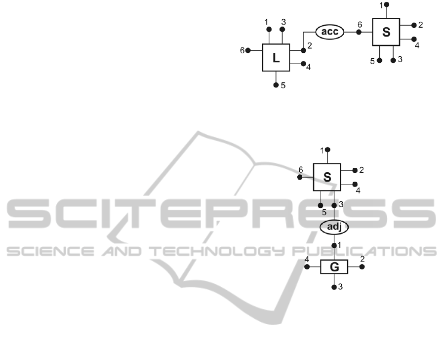
Fig. 5 presents a subgraph of the hypergraph in
Fig. 3 representing accessibility of rooms. The defi-
nition of the adjacency relation (adj) differs from the
definition of accessibility relation (acc) only in the
label of a relational hyper-edge (see: Fig. 6).
Figure 5. A subgraph of the hypergraph in Fig. 3 repre-
senting accessibility of rooms.
Figure 6. A subgraph of the hypergraph in Fig. 3 repre-
senting adjacency of rooms.
Atomic sentences obtained on the basis of the rela-
tions which hold between components of floor lay-
outs constitute syntactic knowledge about the solu-
tions being the result of a design process. In the
running example the knowledge related to the lay-
outs contains sentences concerning direct accessibil-
ity, and adjacency between rooms. The obtained
logical language composed of formulas inferred
from hyper-graphs enables HSSDR system to reason
about compatibility of designs with constraints
specified as a part of general design knowledge.
Rules of the general design knowledge describe de-
sign standards like architectural norms, fire regula-
tions, etc.
Additionally, there exists the possibility to speci-
fy designer’s own requirements in the form of logic
formulas using the rule editor being a part of the
design interface. Designer’s requirement can be as
follows:
x
room area(x)
15. For the layouts
drawn by the designer on an orthogonal grid the sys-
tem automatically calculates the values of the attrib-
ute specifying the area of rooms. Then the reasoning
module can check the agreement between the pro-
posed layout and designer’s requirement.
AnOntologybasedApproachforAssistingConceptualisationinCADProcesses
277

4 CONCLUSION
The separation of designing from making and the
increased importance of the drawing characterise the
modern design process. The major work of initial
conceptual design in CAD is done through a human-
computer dialogue. This paper proposes an ontology
based approach for assisting designer’s conceptuali-
sation in CAD processes. The difficulty lies in the
distinction between the logical notion of model and
the ontological notion of possible worlds (Guarino et
al, 2009). The former is described by abstract struc-
tures, while the letter is represented by observed
states of affairs. The number of world states, i.e., the
number of visual sites, depends mainly on creativity
of the designer.
The role of the logical model is to assign rela-
tional structures to vocabulary elements. Graph can
be combined with the most logic-based knowledge
representation techniques, where knowledge is rep-
resented explicitly by symbolic terms and reasoning
is the manipulation of these terms. In the proposed
approach the semantics of logical formulas uses rela-
tional structures based on hyper-graphs.
It is known that the degree to which an ontology
specifies a conceptualization depends on the rich-
ness both of the domain of discourse and the vo-
cabulary, and logic language expressiveness. In the
considered paper many sorted logic language is used
to express properties of attributed hyper-graphs of
different sorts.
The proposed ontological approach provides in-
sight in how humans aided by computer solve visu-
al design problems. In our future research we shall
consider a new example ontology focusing attention
on influence of computer technology on visual de-
sign creativity.
REFERENCES
Yurchyshyna, A., Zarli, A., 2009. An Ontology-based
Approach for Formalisation and Semantic Organiza-
tion of Conformance Requirements in Construction. In
International Research Journal Automation in Con-
struction. Volume 18. Issue 8, pp. 1084-1098.
Grabska, E., Slusarczyk, G., 2011. Knowledge and reason-
ing in design systems. In Automation in Construction
22, pp. 927–934.
Grabska, E., et al., 2009. Hypergraph system supporting
design and reasoning. In Intelligent Computing in En-
gineering, 20th EG-ICE International Workshop, pp.
134–141.
Grabska, E., 2011. Computer Aided Conceptual Visual
Design based on Ontology, In KEOD, 3
rd
Internation-
al Conference on Knowledge Engineering and Ontol-
ogy Development, pp. 396–399.
Minas, M., 2002. Concepts and Realization of a Diagram
Editor Generator Based on Hypergraph Transfor-
mation. In Science of Computer Programming 44,
2002, pp.157–180.
Coyne, R. D., et al. 1990, Knowledge based design sys-
tems, Addison-Wesley Publishing Company, 1990.
Guarino, N., et al. 2009. What Is an Ontology. Handbook
on Ontologies. Springer, Heildelberg.
Eastman, Ch., et al. 2008. BIM Handbook: A Guide to
Building Information Modeling for Owners, Manag-
ers, Designers, Engineers and Contractors, Wiley.
Lawson, B., 2001, How designers think, Architectural
Press.
Grabska, E., 2010. Visual design with the use of graph-
based data structure. eWork and e-business in Archi-
tecture, Engineering and Construction, Taylor and
Francis Group. London, pp. 209–214.
Tversky, B., Suwa, M., 2009. Thinking with sketches. In
Tools for innovation. Oxford University Press.
Markman, A. B. & Wood, K. L., (Eds.), Tools for innova-
tion, Oxford.
Schurr, A., et al. 1995. Graph grammar engineering with
PROGRES, In LNCS, 989, 5th European Software
Engineering Conference (ESEC95), Springer-Verlag,
Berlin, pp. 219–234.
Visser, W., 2006. The cognitive artifacts of designing,
Erlbaum L. Associates, Mahwah, NJ.
Booch, G., et al. 2005. The unified modeling language
user guide. Addison-Wesley, NJ.
Arciszewski, T., et al. 2009. Visual Thinking in Inventive
Design: Three Perspectives. In Soft Computing in Civil
and Structural Engineering. Saxe-Coburg
Publications, pp. 179 -202.
Tversky, B., 2001. Spatial schemas in depictions. In
Spatial schemas and abstract thought, MIT Press.
Ware, C., 2008. Visual thinking for design, Elsevier.
Goldschmidt, G., 1994. On visual design thinking. In
Design Studies 15, pp.158–174.
Fagin, R., et al. 1995. Reasoning About Knowledge, MIT
Press, Cambridge.
Lifschitz V., Morgenstern L., 2008, Knowledge
Representation and Classical Logic, Handbook of
Knowledge Representation, van Harmelen F.,
Lifschitz V., Porter B. (Eds), Elsevier.
Suwa, M., Tversky, B., 1997. What architects and students
perceive in their sketches: A protocol analysis. In
Design Studies 18, pp. 385–403.
Genesereth M. R., Nilsson N.J., 1987. Logical Foundation
of Artificial Intelligence.
Morgan Kaufmann. Los
Altos. CA.
Grabska E., 2012. Towards a Formal Model of Visual
Design, In Advances in Intelligent and Soft
Computing, Systems Interaction: Backgrounds and
Applications 2, pp. 135–147.
Barwise J., Seligman J., 1997. The Logic of Distributed
Systems, Cambridge University Press.
KEOD2014-InternationalConferenceonKnowledgeEngineeringandOntologyDevelopment
278

Shimojima A., 1996. Operational Constraints in Dia-
grammatic Reasoning. In Logical Reasoning with Di-
agrams. Oxford University Press, pp. 27–48.
Lawson, B., 2001. How designers think: the design
process demystified. Butterworth Architecture.
Oxford.
Grabska, E., et al. 2008. Visual Design and Reasoning
with the Use of Hypergraph Transformations. In
ECEASST 10, pp. 1–15.
Sowa, J. F., 1984. Conceptual Structures: Information
Processing in Mind and Machine. Addison-Wesley.
Ślusarczyk, G., 2011. Visual design with the use of
hierarchical hypergraphs. (in Polish). Studia
Informatica. Silesia University of Technology Press.
AnOntologybasedApproachforAssistingConceptualisationinCADProcesses
279
