
Compensation of Parasitic Effect in Homing Loop with Strapdown
Seeker via PID Control
Ju-Hyeon Hong and Chang-Kyung Ryoo
Department of Aerospace Engineering, Inha University, Inharo100, Incheon, Korea
Keywords: Homing Loop, Strapdown Seeker, Parasitic Effect, PID Controller.
Abstract: Due to seeker delay and coupling with body motion, a strapdown seeker has not been widely used for
missiles though it makes the missile cost cheaper. In this paper, a homing loop design based on PID
controller for missiles with a strapdown seeker is suggested. The PID controller produces body rate
command, instead of estimating line-of-sight(LOS) rate for the proportional navigation guidance. Stability
analysis for linear homing loop has been done to select controller gains. The performance of the designed
terminal homing loop for a small tactical missile against a moving target, where the missile’s strapdown
seeker includes uncertain image processing delay, is verified through full nonlinear 6-DOF simulations.
1 INTRODUCTION
Strapdown seekers have many advantages compared
to gimballed seekers. They are small and light,
requiring less power, and most of all low cost for
production. However, the field of view(FOV) of a
strapdown seeker is narrow and its look angle
measurements are severely correlated with body
motion. Because the strapdown seeker is fixed on
body of missile, it only measures a look angle, the
angle between body axis and the LOS. Hence, to
implement widely used proportional navigation(PN)
guidance, some signal processing techniques to
obtain the LOS rate are required (Ozkan, 2005)
.
Theoretically, the LOS rate can be calculated via
subtracting the body attitude rate simply from the
look angle rate in which the LOS rate is implicitly
included. Typically, the body attitude rate is
measured from a rate gyro, while the look angle rate
is obtained by a numerical filter differentiating the
look angle measured from the seeker. The look angle
measurements from the seeker are delayed due to
target image processing and tracking when it
compared to the body rate from the rate gyro. Due to
the seeker delay, the body attitude rate implicitly
imbedded in the look angle rate cannot be nullified
by the body attitude rate measured by rate gyro. We
call the phenomenon caused by this signal
discrepancy the parasitic effect. Different signal
characteristics between the look angle rate and the
body rate makes the entire missile homing loop
unstable.
Several guidance methods have been studied for
missiles with the strapdown seeker. The most widely
used method is to correct the scale factors which are
located at outputs of seeker and rate gyro of the
homing loop. The extended Kalman filter(EKF) has
been used to estimate scale factor (Mehra, and
Ehrich, 1984). It is reported that the scale factor
uncertainty breaks down the optimality of guidance
(Willman, 1988). The linear quadratic Gaussian
(LQG) method is adopted to replace PN guidance
for missiles with the strapdown seeker where EKF is
also used for estimating the state information
including scale factor error (Vergez and McClendon,
1982)
. The stability of the parasitical loop effected
by scale factor errors has been analysed (Du, Xia,
and Guo, 2010).
While the previous studies mentioned above are
related to estimate the scale factors, there have been
some tries to estimate LOS rate directly by using the
guidance filter for missiles with the strapdown
seeker. The unscented Kalman filter (UKF) is used
to estimate relative motion of the missile to a target
(Yun, Ryoo, and Song, 2009). Instead of estimating
the LOS rate, a look angle control method to deliver
the missile to a destination has been proposed (Kim,
Park, and Ryoo, 2013).
This method is very simple
for implementation and free from parasitic effect
because it does not require any estimation filter. But
the missile behaviour under the look angle control is
711
Hong J. and Ryoo C..
Compensation of Parasitic Effect in Homing Loop with Strapdown Seeker via PID Control.
DOI: 10.5220/0005055907110717
In Proceedings of the 11th International Conference on Informatics in Control, Automation and Robotics (ICINCO-2014), pages 711-717
ISBN: 978-989-758-039-0
Copyright
c
2014 SCITEPRESS (Science and Technology Publications, Lda.)
very similar to that under the pursuit guidance: weak
to disturbances and target manoeuvre. To calculate
LOS rate, the image plane value method is
introduced (Kim, Park, and Lee, 2009). To
compensate the signal difference between the body
attitude rate and the look angle rate, the known
seeker delay is compulsively placed at the rate gyro
output (Jang, Ryoo, Choi, and Tahk, 2008). Here,
the alpha-beta filter to calculate the LOS rate is used.
Routh-Hurwitz stability criterion to select the loop
gain has been also introduced to reduce the parasitic
effect (Kim, Park, Kwon, Kim, and Tahk, 2011).
In this paper, the PID control method is proposed
to stabilize the missile homing loop including the
delay of the strapdown seeker. First, we place the
pure seeker delay on the output of the rate gyro. In
this way, the time difference between the seeker
signal and rate gyro signal is removed. Then, LOS
angle is calculated by subtracting the body attitude
angle which is obtained by integrating the body
attitude rate from the look angle. The PID controller
is then designed to produce the guidance command.
Stability analysis for the linear homing loop is then
done to select PID gains.
In the subsequent section, problems imbedded in
the conventional homing loop of missile with the
strapdown seeker are addressed. In Section 3, the
homing loop design approach based on PID is
introduced. Full nonlinear 6-DOF simulations to
verify the performance of the proposed approach is
performed in Section 4. Section 5 is concluding
remarks.
2 PROBLEM DEFINITION
2.1 Missile Model and Angular
Guidance Command
We consider in this paper that the missile only have
a strapdown seeker and a 3-axis gyroscope. This
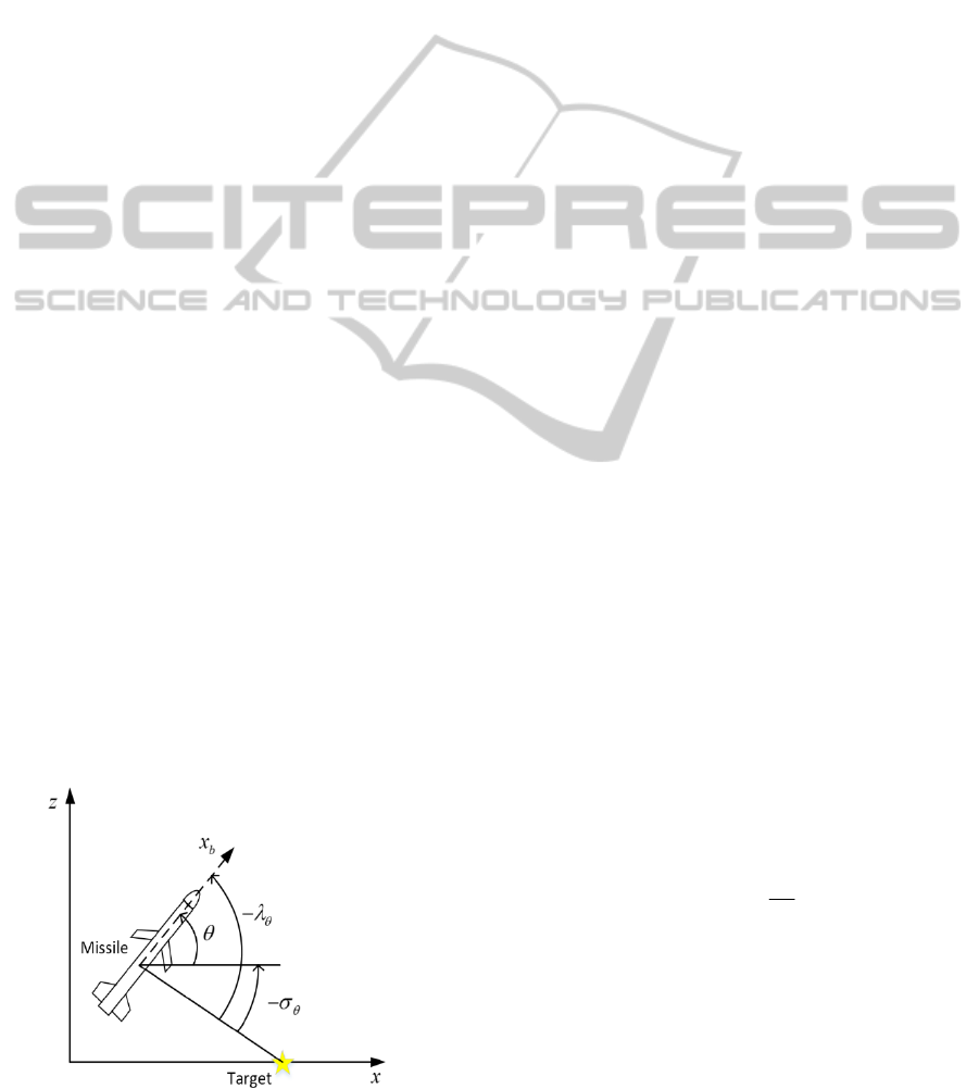
Figure 1: Guidance geometry in the pitch channel.
kind of sensor suites is adequate for a low cost small
tactical missile whose target is likely light armoured
vehicles and bunkers within the range of 1.5km.
In this paper, we assume that roll is tightly
stabilized, and pitch and yaw channel are
independent each other. The guidance geometry at
pitch channel is illustrated on Figure 1.
The LOS angle
is the sum of the body attitude
angle and the look angle. The guidance geometry in
the yaw channel has the same as that of pitch
channel. The equations of the LOS angles in the
pitch channel and the yaw channel are respectively
given by
(1)
where
and
are look angles, respectively and
they are measured by the strapdown seeker. The
body pitch and yaw angles are denoted by
and
,
respectively.
The acceleration commands along with the pitch
and yaw axes are respectively given by
c
x
a
and
c
z
a
.
In case of the proportional navigation guidance, the
guidance commands are given by.
xm
ym
aNV g
aNV
(2)
where
N
the guidance coefficient,
m
V the missile
velocity, and
g
the gravitational acceleration. The
LOS angular rate
in the pitch and yaw channels
is derived by the sum of the body angular rate and
the look angle rate (
).
q
r
(3)
where
q
and
r
are the pitch and yaw angular rate,
respectively. Since the missile has axis gyroscopes
so that the guidance acceleration command must be
converted into the body angular rate command as
follows.
c
m
c
g
qN
V
rN
(4)
where
c
q and
c
r denote the pitch and yaw angular
rate commands, respectively. Since the speed of
missile cannot be measured, the average speed
estimated from simulations is applied to compensate
gravity in (4).
ICINCO2014-11thInternationalConferenceonInformaticsinControl,AutomationandRobotics
712
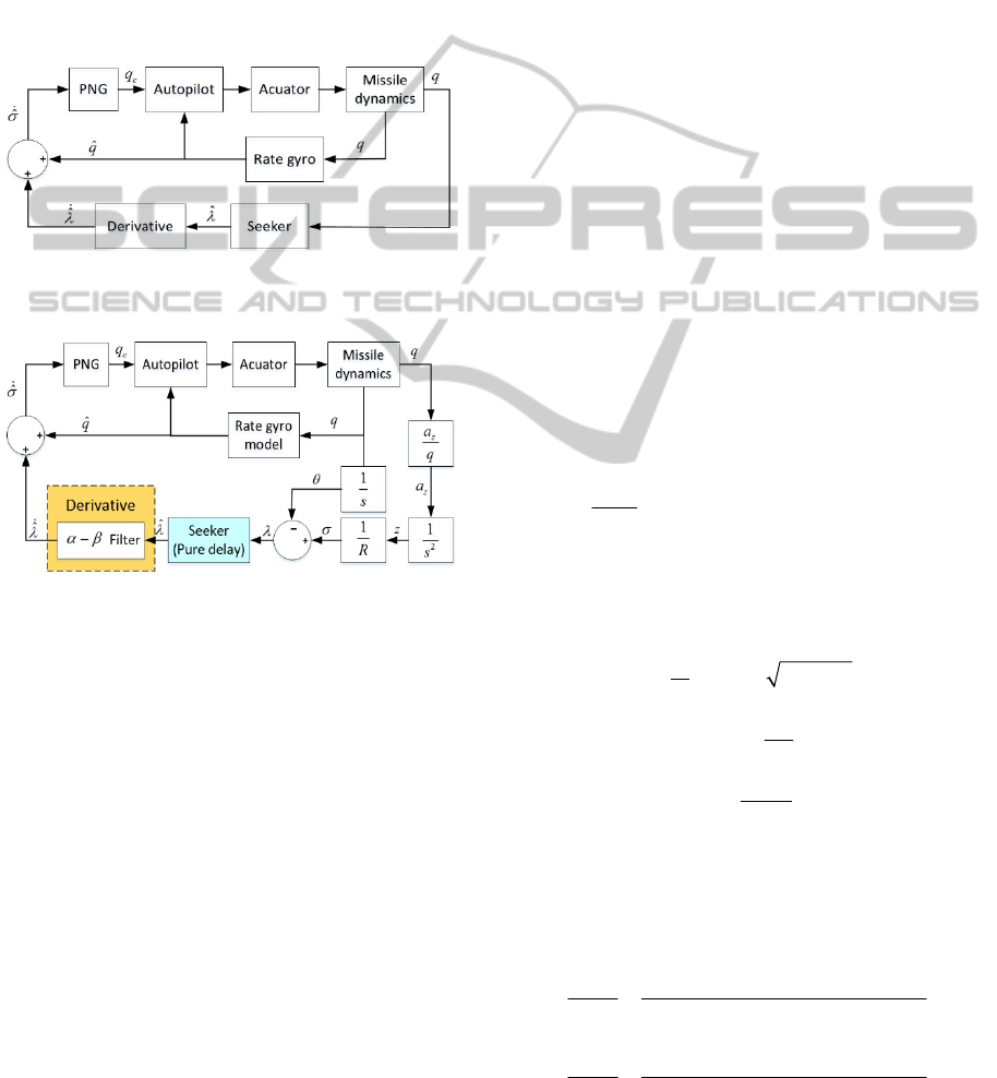
2.2 Ideal Homing Loop
Figure 2 shows the ideal PN homing loop in the
pitch channel for a missile with a strapdown seeker.
Here, the LOS rate
ˆ
for PN is produced by the sum
of the pitch body rate
q
and the look angle rate
ˆ
.
While
q
is measured by the rate gyro,
ˆ
is given by
the derivative of the seeker look angle
. Realizable
homing loop is given in Figure 3, where the
derivative term in Figure 2 is replaced by
filter.
Figure 2: Pitch channel ideal homing loop for missile with
strapdown seeker.
Figure 3: Original homing loop.
2.2.1 Linear Modelling of Time Delay
In order for analysis of homing loop, the time delay
of the seeker and the sampling time are modelled as
()
s
T
Gs e
(5)
/
()
TT
Hz z
(6)
where
T
and
T
denote the time delay time and the
sampling time, respectively. Pade approximation is
used to transform the exponential function in (5) into
rational transfer function (Dorf, and Bishop, 2008).
2.2.2 Design of
Filter (Kalata, 1984)
The
filter can be used for obtaining the look
angle rate (Jang, Ryoo, Choi, and Tahk, 2008). The
state vector is defined by
() () ()
T
x
kkk
. (7)
The system equation and measurement equation are
given by
(1) () ()
x
kxkwk
(8)
2
1
0.5
,,()~(0,)
01
T
T
wk N Q
T
(9)
() () ()
y
khxknk
(10)
10,()~ (0,)
T
hnkNR
(11)
The equations for propagation and updating the state
vector are given by
ˆˆ
(1|) (|)
x
kk xkk
(12)
ˆ
ˆ
(1| 1) (1|)
ˆ
(1)(1) (1|)
xk k xk k
K
kyk hxkk
(13)
/
T
KT
(14)
Based on (12)-(14), the
filter to estimate look
angle rate is given by
ˆ
ˆˆ
() ( 1) ( 1)
ˆˆ
() () ( 1) ( 1)
kk Tk
kk k Tk
(15)
ˆ
ˆ
() ( 1)
()
ˆ
ˆ
() ( 1) ( 1)
kk
k
kk Tk
T
(16)
The filter gains
,
are determined by the
functions of the process and measurement noise
covariances, respectively denoted by
w
and
n
.
2
48
4
(17)
2
2
1
(18)
2
w
n
T
(19)
2.2.3 Transfer Functions of Missile
The transfer functions of the missile for short period
pitch motion are given by e
2
()
() ( ) ( )
q
pqq
Zs M MZ
s
ss ZMsZMM
(20)
2
()
()
()
()( )
p
qq
Ms MZ ZM
qs
s
sZMsZMM
(21)
CompensationofParasiticEffectinHomingLoopwithStrapdownSeekerviaPIDControl
713
where
, , , ,
q
Z
MMZM
are the dimensional
aerodynamic and control derivatives. The transfer
function of the actuator is assumed by 1. And the
transfer function of the pitch rate response to the
pitch rate command, which is based the PI controller,
is given by the following equation
22
()
()
() 2
qt q
c
qq q
KK Ms MZ ZM
qs
qs s s
(22)
2
2
qq q q
qq q
KM Z M
ZM M K MZ ZM
(23)
where
q
and
q
are the damping coefficient and
the natural frequency, which are the design
objectives of the PI controller. Using (23), we can
select the controller gains of
,
qqt
KK
to satisfy
q
and
q
.
The gyroscope model is assumed by the second
order system.
2
22
()
n
gyro
nn
Gs
ss
(24)
The stability of the linear homing loop given in
Figure 3 with the block components described in the
previous section can be done. Note that
, the pitch
attitude, passes through the block components of the
pure delay and the
filter. It means the signal
ˆ
implicitly includes the pitch attitude rate. By
adding
ˆ
q
to
ˆ
, we hope to obtain the LOS rate
ˆ
.
However, the both pitch rate signals are not
compensated each other. It implies that
ˆ
is
corrupted by some signals which comes from the
discrepancy between the pitch rates signals. This
makes the entire homing loop be unstable.
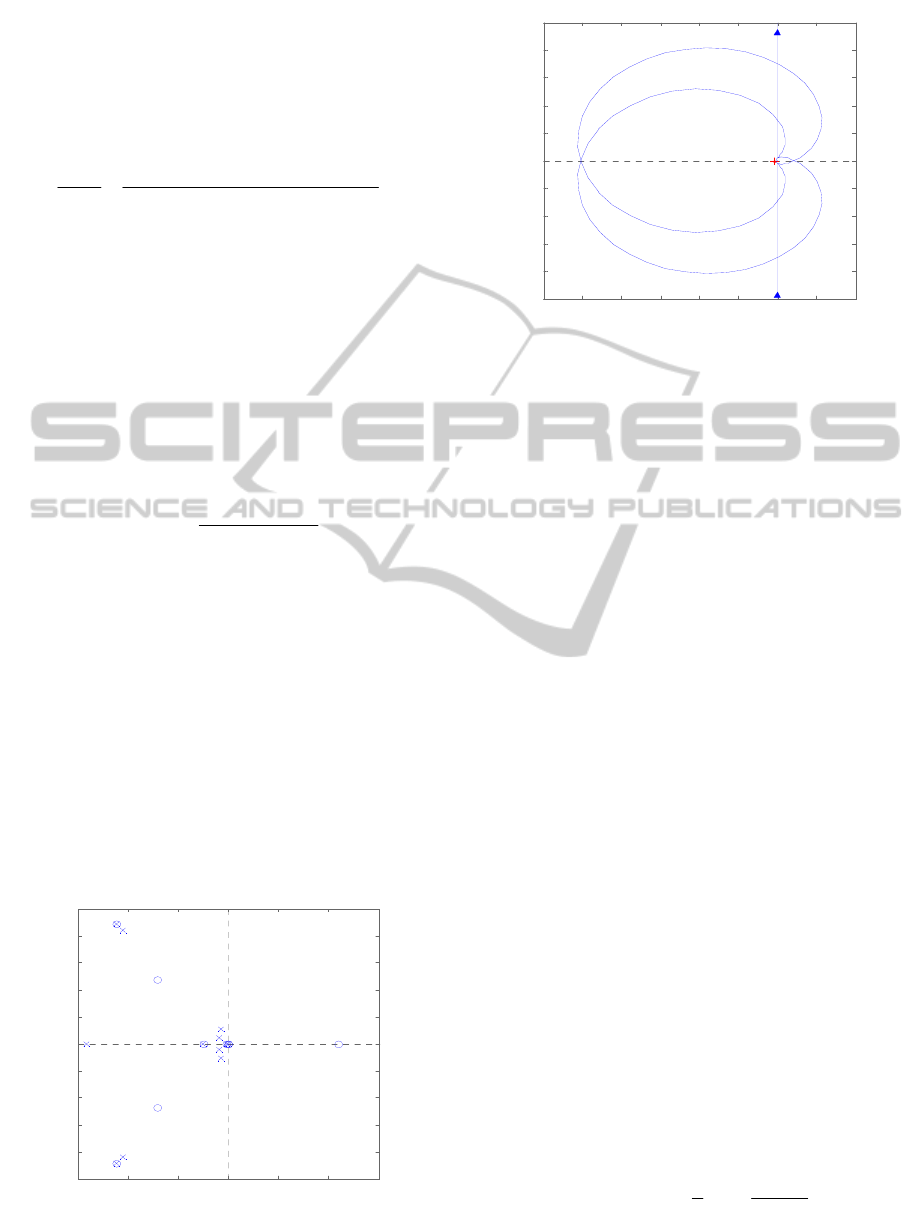
Figure 4: Pole-Zero Map of the original loop.
Figure 5: Nyquist diagram of the original loop.
Figure 4 shows open loop pole-zero map of the
linear model given in Figure 3. Figure 5 shows
Nyquist diagram of this system. Since the number of
counter-clockwise encirclements of the (-1, 0) point
is two, this linear model is unstable even though
there are no poles on the right half plane in Figure 4.
This linear model is made up under the condition
that relative distance is 1500m and velocity is Mach
0.7.
3 HOMING LOOP STABILITY
ENHANCEMENT
3.1 Homing Loop Performance
Improvement through Adding PID
Controller
To remedy the parasitic loop effect, we slightly
modify the linear homing loop. Instead of
introducing the
filter to estimate the look
angle rate, we make the both signals of the gyro and
the seeker coincident with each other by adding
seeker delay and the
filter transfer function to
the signal loop of the gyro and the gyro transfer
function is added to the loop of the seeker as shown
in Figure 6. Even we make the two signal loops
become coincident with each other by adding some
components, there may still signal discrepancies.
Hence we add the PID control loop stabilized the
homing loop as shown in Figure 6. The PID control
loop has the form follows:
1
()
N
PID P I D
N
K
s
GsKK K
s
sK
(25)
-600 -400 -200 0 200 400 600
-500
-400
-300
-200
-100
0
100
200
300
400
500
Pole-Zero Map
Real Axis (seconds
-1
)
Imaginary Axis (seconds
-1
)
-60 -50 -40 -30 -20 -10 0 10 20
-50
-40
-30
-20
-10
0
10
20
30
40
50
Before Correction : Gm=-33.9704[dB] Pm=87.7133[deg]
Real A x is
Imaginary Axis
ICINCO2014-11thInternationalConferenceonInformaticsinControl,AutomationandRobotics
714
Proper choice of gains of PID controller ensures
the linear homing loop invent in Figure 6 stable. As
mentioned before, we assume the range is fixed with
some values to analyse their stability. To ensure the
stability for the entire trajectory, we adopt the gain
scheduling technique to the guidance loop.
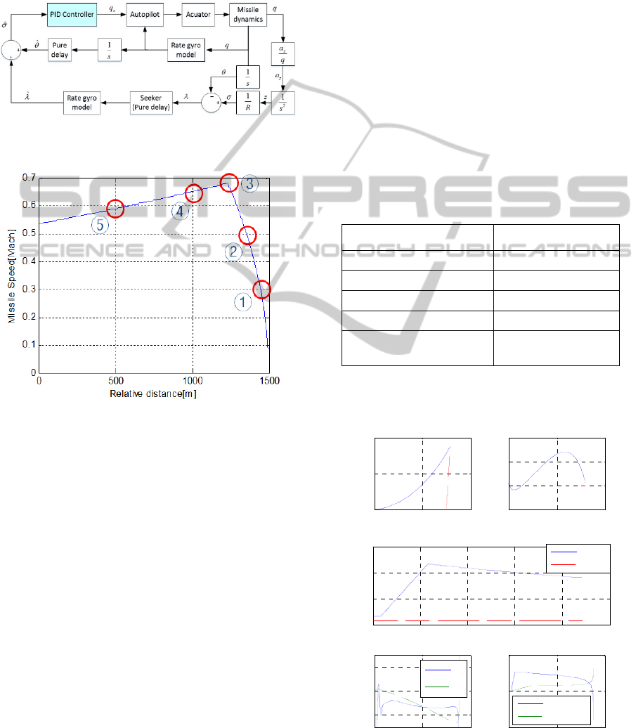
Figure 6: Homing loop with signal compensation and PID
controller.
Figure 7: Design point candidates.
We first selected the gain sets of the PID Controller
at 5 different missile speeds. Each gain set is then
applied to other design points and the stability is
checked. Among 5 gain sets, we can choose one gain
set that guarantees the stability and performance at
all design points. In actual system, we apply this
selected gain set to the whole flight condition
because the missile speed cannot be measured.
Figure 7 shows the example of design points.
The selected design point is the 5th point with the
gain margin is 16.2542dB and phase margin is
58.5176deg. When it applied to other design point,
the smallest gain and phase margin are 7.51dB and
24.7153deg, respectively.
4 SIMULATIONS
Nonlinear 6DOF simulations are performed to
analyse the performance of the proposed homing
loop. Table 1 shows initial conditions of 6 DOF
simulations. The target velocity is 51km/h on
horizontal plane.
Figure 8 shows the nonlinear simulation results
for the standard conditions with no seeker delay
error. In this case, the real seeker delay and the delay
compensation for matching signal characteristics are
the same with 60msec. We can observe from the
figure that the missile states are satisfactorily. Figure
9 and Figure 10 show the nonlinear simulation
results with seeker delay error with -20msec and
20msec, respectively. In these cases, the real seeker
delay time is 60msec, but the models to compensate
the delay in the signal line of rate gyro are 40msec
and 80msec, respectively. Except there are small
oscillations in the initial phase compared to Figure 8,
the missile states are still satisfactorily maintained
for both error cases.
Table 1: Initial conditions for 6-DOF simulation.
Initial value
Initial position of Missile (0m, 0m, 0m)
Initial position of Target (1500m, 0m, 0m)
Initial velocity of Target (10m/s, 10m/s, 0m/s)
Real seeker delay time 60msec
Guidance control loop
sampling time
20msec
The oscillations in the initial phase are turned out to
be within a tolerable range. The guidance errors for
the above three simulation cases are in 2m.
Figure 8: Simulation results without the seeker delay error.
0 1000 2000
0
50
100
X[ m ]
Y[m]
0 1000 2000
-5
0
5
10
X[ m ]
Z[m]
0 2 4 6 8 10
0
100
200
300
Time[ sec ]
Speed[m/sec]
Missile
Target
0 5 10
-2
0
2
Time[ sec ]
Look angle[deg]
0 5 10
-2
0
2
Time[ sec ]
Guid. cmd[g]
Pitch cmd.
Yaw cmd.
CompensationofParasiticEffectinHomingLoopwithStrapdownSeekerviaPIDControl
715
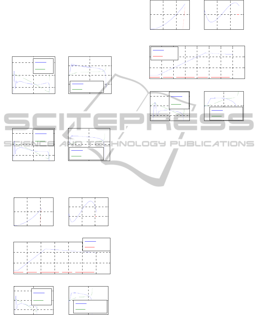
Figure 11 and Figure 12 show the nonlinear
simulation results for applying the gain set to the
different ranges of 1,000m and 500m, respectively.
In these cases, the seeker delay error is not
considered. Even though the controller is designed
for the target with range of 1,500m, the homing loop
is properly working at other target ranges. The
guidance error is bounded within 2m.
Figure 9: Simulation results for the seeker delay error of d
–20msec (40msec pure delay model).
Figure 10: Simulation results for the seeker delay error of
+20msec (80msec pure delay model).
Figure 11: Simulation results for the target range of
1000m.
Figure 12: Simulation results for the target range of 500m.
5 CONCLUSION
In this paper, the controller design method to
compensate the parasitic loop inherently included in
the missile homing loop with the strapdown seeker.
Method which matches signal characteristic between
the seeker delay and the filter dynamics to estimate
the look angle rate are the major elements to make
the homing loop unstable. Loop consistency via
placing the delay and the filter transfer at the output
of the rate gyro is considered. Conventional PID
control technique is then applied to guarantee the
stability of the homing loop against the uncertain
seeker delay errors. Thus the proposed method is to
nullify the LOS angle instead of the nullifying the
LOS rate. Full nonlinear 6-DOF simulations have
been done to verify the performance of the proposed
method.
ACKNOWLEDGEMENTS
This study has been done under the support of the
Agency for Defence Development in Korea.
REFERENCES
Ozkan, B., 2005, Dynamic modelling, guidance, and
0 5 10
-2
0
2
g
Time[ s ec]
Look angle[deg]
0 5 10
-2
-1
0
1
2
Time[ s ec]
Guid. cmd[g]
Pitch cmd.
Yaw cmd.
0 5 10
-2
0
2
Time[ sec ]
Look angle[deg]
0 5 10
-2
0
2
Time[ sec ]
Guid. cmd[g]
Pitch cmd.
Yaw cmd.
0 500 1000 1500
0
50
100
X[ m ]
Y[m]
0 500 1000 1500
-2
0
2
4
X[ m ]
Z[m]
0 1 2 3 4 5 6 7
0
100
200
300
Time[sec]
Speed[m/sec]
Missile
Target
0 5 10
-2
0
2
Time[sec]
Look angle[deg]
0 5 10
-2
0
2
Time[ sec ]
Guid. cmd[g]
Pitch cmd.
Yaw cmd.
0 200 400 600
0
20
40
X[ m ]
Y[m]
0 200 400 600
-2
0
2
X[ m ]
Z[m]
0 0.5 1 1.5 2 2.5 3 3.5 4
0
100
200
300
Ti me[ s ec ]
Speed[m/sec]
Missile
Target
0 2 4
-2
0
2
Ti me[ s ec ]
Look angle[deg]
0 2 4
-2
0
2
Ti me[ s ec ]
Guid. cmd[g]
Pitch cmd.
Yaw cmd.
ICINCO2014-11thInternationalConferenceonInformaticsinControl,AutomationandRobotics
716

control of homing missiles. Ph.D Thesis, Middle east
technical university, pp. 158-159.
Mehra, R. K., and Ehrich, R. D., 1984, “Air-To-Air
Missile Guidance For Strapdown Seekers”,
Proceeding of the 23rd Conference on Decision and
Control, Las Vegas, NV, pp.1109-1115.
Willman, W. W., 1988, “Effects of Strapdown Seeker
Scale-Factor Uncertainty on Optimal Guidance”, J.
Guidance, VOL.11, NO.3, pp.199-206.
Vergez, P. L., and McClendon, R., 1982, “Optimal
Control and Estimation for Strapdown Seeker
Guidance of Tactical Missiles”, J. Guidance, VOL. 5,
NO.3, pp.225-226.
Du, Y. L., Xia, Q. L., and Guo, T., 2010,“Study on
Stability of Strapdown Seeker Scale Factor Error
Parasitical Loop”, Proceeding of 2010 International
Conference on Computer, Mechatronics, Control and
Electronic Engineering (CMCE), VOL. 6, Changchun,
Aug., pp.55-58.
Yun, J., Ryoo, C. K., and Song T. L., 2009, “Guidance
Filter Design Based on Strapdown Seeker and MEMS
Sensors”, Journal of The Korean Society for
Aeronautical and Space Sciences, Vol.37, No.10,
pp.1002-1009.
Kim, D., Park, W., and Ryoo, C. K., 2013, “Look-Angle-
Control Guidance for Missiles with Strapdown
Seeker”, Journal of Institute of Control, Robotics and
Systems, Vol.19, No.3, pp.275-280.
Kim, W. H., Park, C. G., and Lee, J. G., 2009, “A
Derivation of LOS Rate for PNG in a Strapdown
Seeker Missile“, Proceeding of 2009 the Korea
Institute of Military Science and Technology, Jeju,
Korea, pp.354-357.
Jang, S. A., Ryoo, C. K., Choi, K., and Tahk, M. J., 2008,
“Guidance Algorithms for Tactical Missiles with
Strapdown Seeker “, Proceeding of SICE Annual
Conference 2008, Tokyo, pp.2616-2619.
Kim T. H, Park, B. G., Kwon, H. H., Kim Y. H., and
Tahk, M. J., 2011, “Stability Analysis of Missiles with
Strapdown Seeker”, Journal of the Korean Society for
Aeronautical and Space Sciences, Vol.39, No.4,
pp.332-340.
Dorf, R. C., and Bishop, R. H., 2008, Modern Control
Systems, Eleventh edition, Pearson Education, NJ,
pp.604-607.
Kalata, P. R., 1984, “The Tracking Index A Generalized
Parameter for α-β and α-β-γ Target Trackers”, IEEE
Transactions on Aerospace and Electronic Systems,
Volume:AES-20, Issue:2, pp.174-182.
CompensationofParasiticEffectinHomingLoopwithStrapdownSeekerviaPIDControl
717
